PNEUMATIC SYSTEMS AND CONTROL COMPONENTS.pptx
- 1. Unit-III PNEUMATIC SYSTEMS AND CONTROL COMPONENTS MT2351 FLUID POWER SYSTEMS Prepared by: Dr. P. Balasundar, M.E., Ph.D., Assistant Professor (Senior Scale), Department of Mechatronics Engineering, KAMARAJ College of Engineering and Technology.
- 2. PNEUMATIC SYSTEMS AND CONTROL COMPONENTS Basic Components of Pneumatics system: Screw Compressor- Filter, Regulator, Lubricator, Muffler, Air control Valves types, Quick Exhaust valves, Pneumatic actuators. ANSI Symbols. 2
- 3. Introduction ŌĆó Derived from the Greek word ŌĆ£pneumaŌĆØ. ŌĆó It means breath or air. ŌĆó Pneumatics is application of compressed gas (pressurized gas) to power machine or control or regulate machines. ŌĆó Any gas can be used in pneumatic system but air is the most usual. i.e compressed air 3/14/2024 3
- 4. Pneumatics - Definition ŌĆó Pneumatics may be defined as branch of engineering science which deals with the study of the behavior and application of compressed air. ŌĆó Pneumatics can also be defined as the branch of fluid power technology that deals with generation, transmission and control of power using pressurized air. 3/14/2024 4
- 5. Why Pneumatics ? ŌĆó When system required ŌĆó High speed ŌĆó Medium pressure ŌĆó Less accuracy of position ŌĆó Quick response of actuator ŌĆó It is preferred where fire/electric hazard are expected. ŌĆó Wide availability of air. ŌĆó Comparatively cheaper in cost than other systems. 3/14/2024 5
- 6. Properties of air ŌĆó Earth is surrounded by air up to a height of approximately 1600 km above the top surface of the earth ŌĆó Gaseous layer of air around the earth is known as atmosphere ŌĆó Main constituents of air by volume ŌĆó Nitrogen : 78% ŌĆó Oxygen : 21 % ŌĆó -Carbon dioxide & other gases : 1% ŌĆó Air is colourless, odourless, tasteless, and compressible and has weight. 3/14/2024 6
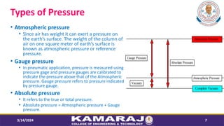
- 7. Types of Pressure ŌĆó Atmospheric pressure ŌĆó Since air has weight it can exert a pressure on the earthŌĆÖs surface. The weight of the column of air on one square meter of earthŌĆÖs surface is known as atmospheric pressure or reference pressure. ŌĆó Gauge pressure ŌĆó In pneumatic application, pressure is measured using pressure gage and pressure gauges are calibrated to indicate the pressure above that of the Atmospheric pressure. Gauge pressure refers to pressure indicated by pressure gauge. ŌĆó Absolute pressure ŌĆó It refers to the true or total pressure. ŌĆó Absolute pressure = Atmospheric pressure + Gauge pressure. 3/14/2024 7 Atmospheric Pressure Vacuum Gauge Pressure Absolute Pressure Complete Vacuum Measured Pressure
- 8. Gas Laws ŌĆó Early experiments were conducted concerning the behaviour of air and similar gases. ŌĆó These experiments were conducted by scientists such as Boyle, Charles and Gay-Lussac. ŌĆó The results of their experiments indicated that gases behaviours follow the law known as ideal gas laws. 3/14/2024 8
- 9. BoyleŌĆÖs Law ŌĆó Robert Boyle (1627-1691), an English scientist, was among the first to experiment with the pressure volume relationship of gas at constant temperature. 3/14/2024 9 Robert Boyle (1627ŌĆō91)
- 10. CharleŌĆÖs Law ŌĆó Jacques Charles (1746 to 1823),a French physicist, provided much of the foundations for modern kinetic theory of gases. ŌĆó Through experiments, he found that all gases expand and contract proportionally to the change in the absolute temperature, providing the pressure remains constant. 3/14/2024 10 Jacques Alexandre C├®sar Charles, 1820
- 11. Gay-LussacŌĆÖs Law ŌĆó A third gas law may be derived as a corollary to Boyle's and Charles's laws. ŌĆó This law was first stated by the Frenchman Joseph Gay-Lussac (1778 to 1850). ŌĆó At constant pressure, the absolute pressure of an ideal gas will vary directly with the absolute temperature. 3/14/2024 11 Joseph Louis Gay-Lussac, 1850
- 12. Basic Components of Pneumatic Systems 3/14/2024 12
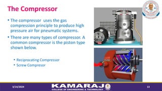
- 13. The Compressor ŌĆó The compressor uses the gas compression principle to produce high pressure air for pneumatic systems. ŌĆó There are many types of compressor. A common compressor is the piston type shown below. ŌĆó Reciprocating Compressor ŌĆó Screw Compresor 3/14/2024 13
- 14. The Receiver ŌĆó The receiver collects and stores the air from the compressor. 3/14/2024 14
- 15. Filter ŌĆó Air filter and water trap is used to prevent any solid contaminants from entering in the system. ŌĆó condense and remove water vapor that is present in the compressed air. 3/14/2024 15
- 16. Regulator ŌĆó Regulator is used to provide a constant outlet of pressure, separately from the inlet pressure or flow. ŌĆó Used for stabilizing the force applied to cylinders or minimizing pressure variation. 3/14/2024 16
- 17. Lubricator ŌĆó The compressed air is first filtered and then passed through a lubricator in order to form a mist of oil and air to provide lubrication to the mating components. 3/14/2024 17
- 18. FRL UNIT - Filter Regulator Lubricator 3/14/2024 18 ’ü¼ FRL Combined unit ’ü¼ FRL Simplified symbol
- 19. FRL UNIT - Filter Regulator Lubricator 3/14/2024 19
- 20. Muffler ŌĆó A muffler or silencer is a device for reducing the noise emitted by the exhaust of pneumatic system. ŌĆó Mufflers are used mainly to dissipate the loud sounds created by the engine's pistons and valves. ŌĆó The muffler is a part of the exhaust which deadens the sound from the pneumatic systems. 3/14/2024 20
- 21. Air Dryer ŌĆó The compression process produces a lot of water which is forced out of the compressed air. The water must be removed using a dryer. 3/14/2024 21
- 22. Pneumatic Air Distribution System 3/14/2024 22
- 23. Pneumatic Components ŌĆó Pneumatic Actuators ŌĆó Single acting cylinder ŌĆó Double acting cylinder ŌĆó Tandem Cylinders ŌĆó Rod less Cylinders ŌĆó Telescopic Cylinders ŌĆó Pneumatic Air Control Valves ŌĆó Direction Control Valves (DCV) ŌĆó Pressure Control Valves (PCV) ŌĆó Flow Control Valves (FCV) 3/14/2024 23
- 24. Quick Exhaust Valve ŌĆó Quick Exhaust valves are mainly used to increase the extending speed of the piston by direct venting ŌĆó Quick exhaust valves are always installed in the vent side directly on the cylinder. 3/14/2024 24
- 25. FLUID SYMBOLS ŌĆó A family of graphic symbols has been developed to represent fluid power components and systems on schematic drawings. ŌĆó https://www.valmet.com/media/articles/up- and-running/reliability/FRFluidDwgs1/ ŌĆó https://engineeringlibrary.org/reference/hydraul ics-graphic-symbols-for-fluid-power-diagrams- navy 3/14/2024 25


