ºÝºÝߣ

ºÝºÝߣShare a Scribd company logo
The power system network consists the following major
components:
 Generator
 Transmission line
 Distribution line
 Load
 Transformer
Generation: (Generator)
In generation the energy is converted from one form to
other forms and it voltage level be 6.6KV, 10.5KV, 11KV,
13.8KV and 15.75KV
Sending end substation: (Step up transformer)
The generated power can be transmitted by increasing
the voltage level to 110 KV, 132KV, 220KV, 400KV and
765KV, this stage is known as primary transmission.
Receiving end substation: (Step down transformer)
In this stage the voltage level is reduced to 66KV, 33KV.
This level is known as Secondary transmission.
Structure of Power System
Mr.C.Anandhakumar, AP / EEE, SRIT
POWER SYSTEM ANALYSIS
Receiving end substation: (Step down transformer)
In this stage the voltage level is reduced to 66KV, 33KV. This level is known as Secondary transmission.
Secondary substation: (Step down transformer)
In here the voltage level is reduced to 11KV, 6.6KV and 3.3KV. This level is known as Primary Distribution.
From this stage we can directly supply to the industries
Distribution station: (Step down transformer)
In here the voltage level is reduced to 440V, and 230V. This level is known as Secondary Distribution.
From this stage we can directly supply to the Commercial and Domestic loads.
Service Mains: (Distributed Transformer)
From here we can give supply to the various consumers.
The power system operation and planning can be done in by
 Load flow or Power flow Analysis
 Fault Analysis
 Stability Analysis
Structure of Power System Conti…
Mr.C.Anandhakumar, AP / EEE, SRIT
POWER SYSTEM ANALYSIS
The actual power is comprised of two components
1.Active power (resistive portion) in KW
2. Reactive power (Reactive portion) in Kvar
Cumulatively know as apparent power in KVA 90 degree phase difference between KW and Kvar.
Some related terms
KW = KVA cosθ
KVA=KW / cosθ
Kvar = KVA sinθ
Power Factor = cosθ
Power Factor
Mr.C.Anandhakumar, AP / EEE, SRIT
POWER SYSTEM ANALYSIS
Per Unit System
Mr.C.Anandhakumar, AP / EEE, SRIT
POWER SYSTEM ANALYSIS
Definition:
Its is defined as the ratio of actual quantity to its base quantity expressed as a decimal.
Both Actual and base values are in same units, So p.u. is dimensionless.
Advantages of p.u.:
 It gives valuable relative magnitude information.
 Transformers transformation ratio is greatly simplified.
 Its ideal for computerized analysis and simulation of complex power system problems.
 Manufactures can easily specify the impedance value in p.u.
 The circuit laws are valid
 Due to p.u. representation the three phase values are easy to estimate.
Note:
V, I, KVA and Z are so related that the selection of base values for any two of them
determines the base value of the remaining two.
POWER SYSTEM ANALYSIS
Steps to draw the p.u. Impedance Diagram
Mr.C.Anandhakumar, AP / EEE, SRIT
POWER SYSTEM ANALYSIS








ï‚´








ï‚´

given
b
new
b
new
b
given
b
given
u
p
new
u
p
MVA
MVA
KV
KV
Z
Z
,
,
2
,
,
,
.
,
.
  b
b
actual
base
actual
new
u
p MVA
KV
Z
Z
Z
Z ï‚´
ï‚´
 2
,
.
Step 1:
Choose common MVA or base MVA for the given systems. (Mostly highest generator rating is taken)
Step 2:
Choose an appropriate base KV for each and every section. (In any side change occurs or presence of
transformer, recalculate new base KV using transformation ratio)
Step 3:
Calculate p.u. impedance in each section.
Formula for generator, Motor and Transformer:
Formula for transmission line:
Step 4:
Draw the impedance diagram from one line diagram.
old
b
KV , new
b
KV ,
V
L. V
H.
rating
side
LT
rating
side
HT
,
, ï‚´
 old
b
new
b KV
KV
Impedance Diagram
Mr.C.Anandhakumar, AP / EEE, SRIT
6/14/2024
POWER SYSTEM ANALYSIS
The impedance diagram on single phase basis under balanced operating conditions can be drawn from
one line diagram.
1
E 3
E
2
E
1
Z
1
T
Z
1
T
Z
l
Z
l
Z
2
T
Z
2
T
Z
2
Z 3
Z L
Z
Reactance Diagram
1
E 3
E
2
E
1
X
1
T
X l
X 2
T
X
2
X L
X
1
T
X l
X 2
T
X 3
X
Formation of Y-Bus by Two rule method or
Inspection Method
Mr.C.Anandhakumar, AP / EEE, SRIT
POWER SYSTEM ANALYSIS
Introduction:
 An interconnected power system represents an electric network with a multitude of branches and nodes.
 The transmission lines constitute the branches.
 In some of the buses power being injected into the network (Generator Bus)
 Other buses power being tapped for loads (Load Bus)
Bus Matrix Classification:
 Admittance Bus ( Y Bus) - Applications in Load flow and stability analysis.
 Impedance Bus (Z bus) – Applications in Short Circuit analysis
The above said two bus matrix find the applications in power system planning and operational studies.
The injected bus currents and bus voltages of a power system under steady state condition can be regulated through
these matrices as
[V]
[Z][I]
[I]
[Y][V]


Power Flow Analysis
Mr.C.Anandhakumar, AP / EEE, SRIT
6/14/2024
POWER SYSTEM ANALYSIS
Classification of buses:
 Slack Bus or Ref Bus
 P-V Bus or Generator Bus
 P-Q Bus or Load Bus
S.No Bus Quantities
Specified
Quantities to be
specified
1. Slack bus or Ref Bus V, δ P, Q
2. P-V Bus or Generator Bus P, V Q, δ
3. P-Q Bus or Load Bus P, Q V, δ
Where,
P = PG - PL
Q = QG – QL
PG = Real power generated by generator connected to the bus.
QG = Reactive power generated by generator connected to the bus.
PL = Real power drawn by the load.
QL = Reactive power drawn by the load.

More Related Content

Similar to Power System Analysis introductionslide.pptx (20)

A High Performance PWM Voltage Source Inverter Used for VAR Compensation and ...
A High Performance PWM Voltage Source Inverter Used for VAR Compensation and ...A High Performance PWM Voltage Source Inverter Used for VAR Compensation and ...
A High Performance PWM Voltage Source Inverter Used for VAR Compensation and ...
IJMER
Ìý
Power Flow & Voltage Stability Analysis using MATLAB
Power Flow & Voltage Stability Analysis using MATLAB Power Flow & Voltage Stability Analysis using MATLAB
Power Flow & Voltage Stability Analysis using MATLAB
IRJET Journal
Ìý
IRJET-Power Flow & Voltage Stability Analysis using MATLAB
IRJET-Power Flow & Voltage Stability Analysis using MATLAB IRJET-Power Flow & Voltage Stability Analysis using MATLAB
IRJET-Power Flow & Voltage Stability Analysis using MATLAB
IRJET Journal
Ìý
Power System Analysis!
Power System Analysis!Power System Analysis!
Power System Analysis!
PRABHAHARAN429
Ìý
An Enhancement of Power Quality by the use of D-STATCOM and Soft Computing Te...
An Enhancement of Power Quality by the use of D-STATCOM and Soft Computing Te...An Enhancement of Power Quality by the use of D-STATCOM and Soft Computing Te...
An Enhancement of Power Quality by the use of D-STATCOM and Soft Computing Te...
IJMTST Journal
Ìý
A three phase ups systems operating under nonlinear loads with modified spwm ...
A three phase ups systems operating under nonlinear loads with modified spwm ...A three phase ups systems operating under nonlinear loads with modified spwm ...
A three phase ups systems operating under nonlinear loads with modified spwm ...
EditorIJAERD
Ìý
Selective localization of capacitor banks considering stability aspects in po...
Selective localization of capacitor banks considering stability aspects in po...Selective localization of capacitor banks considering stability aspects in po...
Selective localization of capacitor banks considering stability aspects in po...
IAEME Publication
Ìý
Ee423 fault analysis_notes
Ee423  fault analysis_notesEe423  fault analysis_notes
Ee423 fault analysis_notes
Acot Benard
Ìý
Ki3418621868
Ki3418621868Ki3418621868
Ki3418621868
IJERA Editor
Ìý
Cascaded Multilevel Inverter Based Active Power Filters: A Survey of Controls
Cascaded Multilevel Inverter Based Active Power Filters: A Survey of ControlsCascaded Multilevel Inverter Based Active Power Filters: A Survey of Controls
Cascaded Multilevel Inverter Based Active Power Filters: A Survey of Controls
IOSR Journals
Ìý
Electrical power system
Electrical power system Electrical power system
Electrical power system
Surbhi Shrivastava
Ìý
DC Bus Voltage Switched Control Method for Three Phase Voltage Source PWM Rec...
DC Bus Voltage Switched Control Method for Three Phase Voltage Source PWM Rec...DC Bus Voltage Switched Control Method for Three Phase Voltage Source PWM Rec...
DC Bus Voltage Switched Control Method for Three Phase Voltage Source PWM Rec...
ijsrd.com
Ìý
Estimation of Harmonics in Three-phase and Six-phase (Multi- phase) Load Circ...
Estimation of Harmonics in Three-phase and Six-phase (Multi- phase) Load Circ...Estimation of Harmonics in Three-phase and Six-phase (Multi- phase) Load Circ...
Estimation of Harmonics in Three-phase and Six-phase (Multi- phase) Load Circ...
IAES-IJPEDS
Ìý
Unit -1 Introdcution to PSA.pptx
Unit -1  Introdcution to PSA.pptxUnit -1  Introdcution to PSA.pptx
Unit -1 Introdcution to PSA.pptx
SanjeevKumarkumar11
Ìý
Implementation of Instantaneous Reactive Power Theory for Current Harmonic Re...
Implementation of Instantaneous Reactive Power Theory for Current Harmonic Re...Implementation of Instantaneous Reactive Power Theory for Current Harmonic Re...
Implementation of Instantaneous Reactive Power Theory for Current Harmonic Re...
IOSR Journals
Ìý
K010126874
K010126874K010126874
K010126874
IOSR Journals
Ìý
Closed Loop Non Linear Control of Shunt Hybrid Power Filter for Harmonics Mit...
Closed Loop Non Linear Control of Shunt Hybrid Power Filter for Harmonics Mit...Closed Loop Non Linear Control of Shunt Hybrid Power Filter for Harmonics Mit...
Closed Loop Non Linear Control of Shunt Hybrid Power Filter for Harmonics Mit...
IAES-IJPEDS
Ìý
Ee 1351 power system analysis
Ee 1351 power system analysisEe 1351 power system analysis
Ee 1351 power system analysis
Hari Kumar
Ìý
40220140501007 2
40220140501007 240220140501007 2
40220140501007 2
IAEME Publication
Ìý
Facts devices mayank
Facts devices mayankFacts devices mayank
Facts devices mayank
Mayank Sharma
Ìý
A High Performance PWM Voltage Source Inverter Used for VAR Compensation and ...
A High Performance PWM Voltage Source Inverter Used for VAR Compensation and ...A High Performance PWM Voltage Source Inverter Used for VAR Compensation and ...
A High Performance PWM Voltage Source Inverter Used for VAR Compensation and ...
IJMER
Ìý
Power Flow & Voltage Stability Analysis using MATLAB
Power Flow & Voltage Stability Analysis using MATLAB Power Flow & Voltage Stability Analysis using MATLAB
Power Flow & Voltage Stability Analysis using MATLAB
IRJET Journal
Ìý
IRJET-Power Flow & Voltage Stability Analysis using MATLAB
IRJET-Power Flow & Voltage Stability Analysis using MATLAB IRJET-Power Flow & Voltage Stability Analysis using MATLAB
IRJET-Power Flow & Voltage Stability Analysis using MATLAB
IRJET Journal
Ìý
Power System Analysis!
Power System Analysis!Power System Analysis!
Power System Analysis!
PRABHAHARAN429
Ìý
An Enhancement of Power Quality by the use of D-STATCOM and Soft Computing Te...
An Enhancement of Power Quality by the use of D-STATCOM and Soft Computing Te...An Enhancement of Power Quality by the use of D-STATCOM and Soft Computing Te...
An Enhancement of Power Quality by the use of D-STATCOM and Soft Computing Te...
IJMTST Journal
Ìý
A three phase ups systems operating under nonlinear loads with modified spwm ...
A three phase ups systems operating under nonlinear loads with modified spwm ...A three phase ups systems operating under nonlinear loads with modified spwm ...
A three phase ups systems operating under nonlinear loads with modified spwm ...
EditorIJAERD
Ìý
Selective localization of capacitor banks considering stability aspects in po...
Selective localization of capacitor banks considering stability aspects in po...Selective localization of capacitor banks considering stability aspects in po...
Selective localization of capacitor banks considering stability aspects in po...
IAEME Publication
Ìý
Ee423 fault analysis_notes
Ee423  fault analysis_notesEe423  fault analysis_notes
Ee423 fault analysis_notes
Acot Benard
Ìý
Ki3418621868
Ki3418621868Ki3418621868
Ki3418621868
IJERA Editor
Ìý
Cascaded Multilevel Inverter Based Active Power Filters: A Survey of Controls
Cascaded Multilevel Inverter Based Active Power Filters: A Survey of ControlsCascaded Multilevel Inverter Based Active Power Filters: A Survey of Controls
Cascaded Multilevel Inverter Based Active Power Filters: A Survey of Controls
IOSR Journals
Ìý
Electrical power system
Electrical power system Electrical power system
Electrical power system
Surbhi Shrivastava
Ìý
DC Bus Voltage Switched Control Method for Three Phase Voltage Source PWM Rec...
DC Bus Voltage Switched Control Method for Three Phase Voltage Source PWM Rec...DC Bus Voltage Switched Control Method for Three Phase Voltage Source PWM Rec...
DC Bus Voltage Switched Control Method for Three Phase Voltage Source PWM Rec...
ijsrd.com
Ìý
Estimation of Harmonics in Three-phase and Six-phase (Multi- phase) Load Circ...
Estimation of Harmonics in Three-phase and Six-phase (Multi- phase) Load Circ...Estimation of Harmonics in Three-phase and Six-phase (Multi- phase) Load Circ...
Estimation of Harmonics in Three-phase and Six-phase (Multi- phase) Load Circ...
IAES-IJPEDS
Ìý
Unit -1 Introdcution to PSA.pptx
Unit -1  Introdcution to PSA.pptxUnit -1  Introdcution to PSA.pptx
Unit -1 Introdcution to PSA.pptx
SanjeevKumarkumar11
Ìý
Implementation of Instantaneous Reactive Power Theory for Current Harmonic Re...
Implementation of Instantaneous Reactive Power Theory for Current Harmonic Re...Implementation of Instantaneous Reactive Power Theory for Current Harmonic Re...
Implementation of Instantaneous Reactive Power Theory for Current Harmonic Re...
IOSR Journals
Ìý
Closed Loop Non Linear Control of Shunt Hybrid Power Filter for Harmonics Mit...
Closed Loop Non Linear Control of Shunt Hybrid Power Filter for Harmonics Mit...Closed Loop Non Linear Control of Shunt Hybrid Power Filter for Harmonics Mit...
Closed Loop Non Linear Control of Shunt Hybrid Power Filter for Harmonics Mit...
IAES-IJPEDS
Ìý
Ee 1351 power system analysis
Ee 1351 power system analysisEe 1351 power system analysis
Ee 1351 power system analysis
Hari Kumar
Ìý
Facts devices mayank
Facts devices mayankFacts devices mayank
Facts devices mayank
Mayank Sharma
Ìý

Recently uploaded (20)

TM-ASP-101-RF_Air Press manual crimping machine.pdf
TM-ASP-101-RF_Air Press manual crimping machine.pdfTM-ASP-101-RF_Air Press manual crimping machine.pdf
TM-ASP-101-RF_Air Press manual crimping machine.pdf
ChungLe60
Ìý
GREEN BULIDING PPT FOR THE REFRENACE.PPT
GREEN BULIDING PPT FOR THE REFRENACE.PPTGREEN BULIDING PPT FOR THE REFRENACE.PPT
GREEN BULIDING PPT FOR THE REFRENACE.PPT
kamalkeerthan61
Ìý
CONTRACTOR ALL RISK INSURANCESAR (1).ppt
CONTRACTOR ALL RISK INSURANCESAR (1).pptCONTRACTOR ALL RISK INSURANCESAR (1).ppt
CONTRACTOR ALL RISK INSURANCESAR (1).ppt
suaktonny
Ìý
Taykon-Kalite belgeleri
Taykon-Kalite belgeleriTaykon-Kalite belgeleri
Taykon-Kalite belgeleri
TAYKON
Ìý
04 MAINTENANCE OF CONCRETE PAVEMENTS.ppt
04  MAINTENANCE OF CONCRETE PAVEMENTS.ppt04  MAINTENANCE OF CONCRETE PAVEMENTS.ppt
04 MAINTENANCE OF CONCRETE PAVEMENTS.ppt
sreenath seenu
Ìý
Cyber Security_ Protecting the Digital World.pptx
Cyber Security_ Protecting the Digital World.pptxCyber Security_ Protecting the Digital World.pptx
Cyber Security_ Protecting the Digital World.pptx
Harshith A S
Ìý
Name.docxVVVVVVVVVVVVVVVVVVVVVVVVVVVVVVVVVVVVVVVVVVVV
Name.docxVVVVVVVVVVVVVVVVVVVVVVVVVVVVVVVVVVVVVVVVVVVVName.docxVVVVVVVVVVVVVVVVVVVVVVVVVVVVVVVVVVVVVVVVVVVV
Name.docxVVVVVVVVVVVVVVVVVVVVVVVVVVVVVVVVVVVVVVVVVVVV
MerijimArsedelPalmad1
Ìý
Embedded System intro Embedded System intro.ppt
Embedded System intro Embedded System intro.pptEmbedded System intro Embedded System intro.ppt
Embedded System intro Embedded System intro.ppt
23ucc580
Ìý
GROUP-3-GRID-CODE-AND-DISTRIBUTION-CODE.pptx
GROUP-3-GRID-CODE-AND-DISTRIBUTION-CODE.pptxGROUP-3-GRID-CODE-AND-DISTRIBUTION-CODE.pptx
GROUP-3-GRID-CODE-AND-DISTRIBUTION-CODE.pptx
meneememoo
Ìý
Env and Water Supply Engg._Dr. Hasan.pdf
Env and Water Supply Engg._Dr. Hasan.pdfEnv and Water Supply Engg._Dr. Hasan.pdf
Env and Water Supply Engg._Dr. Hasan.pdf
MahmudHasan747870
Ìý
Cloud Computing concepts and technologies
Cloud Computing concepts and technologiesCloud Computing concepts and technologies
Cloud Computing concepts and technologies
ssuser4c9444
Ìý
15. Smart Cities Big Data, Civic Hackers, and the Quest for a New Utopia.pdf
15. Smart Cities Big Data, Civic Hackers, and the Quest for a New Utopia.pdf15. Smart Cities Big Data, Civic Hackers, and the Quest for a New Utopia.pdf
15. Smart Cities Big Data, Civic Hackers, and the Quest for a New Utopia.pdf
NgocThang9
Ìý
US Patented ReGenX Generator, ReGen-X Quatum Motor EV Regenerative Accelerati...
US Patented ReGenX Generator, ReGen-X Quatum Motor EV Regenerative Accelerati...US Patented ReGenX Generator, ReGen-X Quatum Motor EV Regenerative Accelerati...
US Patented ReGenX Generator, ReGen-X Quatum Motor EV Regenerative Accelerati...
Thane Heins NOBEL PRIZE WINNING ENERGY RESEARCHER
Ìý
IPC-9716_2024 Requirements for Automated Optical Inspection (AOI) Process Con...
IPC-9716_2024 Requirements for Automated Optical Inspection (AOI) Process Con...IPC-9716_2024 Requirements for Automated Optical Inspection (AOI) Process Con...
IPC-9716_2024 Requirements for Automated Optical Inspection (AOI) Process Con...
ssuserd9338b
Ìý
Piping-and-pipeline-calculations-manual.pdf
Piping-and-pipeline-calculations-manual.pdfPiping-and-pipeline-calculations-manual.pdf
Piping-and-pipeline-calculations-manual.pdf
OMI0721
Ìý
CFOT Fiber Optics FOA CERTIFICATION.pptx
CFOT Fiber Optics FOA CERTIFICATION.pptxCFOT Fiber Optics FOA CERTIFICATION.pptx
CFOT Fiber Optics FOA CERTIFICATION.pptx
MohamedShabana37
Ìý
Mathematics behind machine learning INT255 INT255__Unit 3__PPT-1.pptx
Mathematics behind machine learning INT255 INT255__Unit 3__PPT-1.pptxMathematics behind machine learning INT255 INT255__Unit 3__PPT-1.pptx
Mathematics behind machine learning INT255 INT255__Unit 3__PPT-1.pptx
ppkmurthy2006
Ìý
Mathematics_behind_machine_learning_INT255.pptx
Mathematics_behind_machine_learning_INT255.pptxMathematics_behind_machine_learning_INT255.pptx
Mathematics_behind_machine_learning_INT255.pptx
ppkmurthy2006
Ìý
Industrial Valves, Instruments Products Profile
Industrial Valves, Instruments Products ProfileIndustrial Valves, Instruments Products Profile
Industrial Valves, Instruments Products Profile
zebcoeng
Ìý
Equipment for Gas Metal Arc Welding Process
Equipment for Gas Metal Arc Welding ProcessEquipment for Gas Metal Arc Welding Process
Equipment for Gas Metal Arc Welding Process
AhmadKamil87
Ìý
TM-ASP-101-RF_Air Press manual crimping machine.pdf
TM-ASP-101-RF_Air Press manual crimping machine.pdfTM-ASP-101-RF_Air Press manual crimping machine.pdf
TM-ASP-101-RF_Air Press manual crimping machine.pdf
ChungLe60
Ìý
GREEN BULIDING PPT FOR THE REFRENACE.PPT
GREEN BULIDING PPT FOR THE REFRENACE.PPTGREEN BULIDING PPT FOR THE REFRENACE.PPT
GREEN BULIDING PPT FOR THE REFRENACE.PPT
kamalkeerthan61
Ìý
CONTRACTOR ALL RISK INSURANCESAR (1).ppt
CONTRACTOR ALL RISK INSURANCESAR (1).pptCONTRACTOR ALL RISK INSURANCESAR (1).ppt
CONTRACTOR ALL RISK INSURANCESAR (1).ppt
suaktonny
Ìý
Taykon-Kalite belgeleri
Taykon-Kalite belgeleriTaykon-Kalite belgeleri
Taykon-Kalite belgeleri
TAYKON
Ìý
04 MAINTENANCE OF CONCRETE PAVEMENTS.ppt
04  MAINTENANCE OF CONCRETE PAVEMENTS.ppt04  MAINTENANCE OF CONCRETE PAVEMENTS.ppt
04 MAINTENANCE OF CONCRETE PAVEMENTS.ppt
sreenath seenu
Ìý
Cyber Security_ Protecting the Digital World.pptx
Cyber Security_ Protecting the Digital World.pptxCyber Security_ Protecting the Digital World.pptx
Cyber Security_ Protecting the Digital World.pptx
Harshith A S
Ìý
Name.docxVVVVVVVVVVVVVVVVVVVVVVVVVVVVVVVVVVVVVVVVVVVV
Name.docxVVVVVVVVVVVVVVVVVVVVVVVVVVVVVVVVVVVVVVVVVVVVName.docxVVVVVVVVVVVVVVVVVVVVVVVVVVVVVVVVVVVVVVVVVVVV
Name.docxVVVVVVVVVVVVVVVVVVVVVVVVVVVVVVVVVVVVVVVVVVVV
MerijimArsedelPalmad1
Ìý
Embedded System intro Embedded System intro.ppt
Embedded System intro Embedded System intro.pptEmbedded System intro Embedded System intro.ppt
Embedded System intro Embedded System intro.ppt
23ucc580
Ìý
GROUP-3-GRID-CODE-AND-DISTRIBUTION-CODE.pptx
GROUP-3-GRID-CODE-AND-DISTRIBUTION-CODE.pptxGROUP-3-GRID-CODE-AND-DISTRIBUTION-CODE.pptx
GROUP-3-GRID-CODE-AND-DISTRIBUTION-CODE.pptx
meneememoo
Ìý
Env and Water Supply Engg._Dr. Hasan.pdf
Env and Water Supply Engg._Dr. Hasan.pdfEnv and Water Supply Engg._Dr. Hasan.pdf
Env and Water Supply Engg._Dr. Hasan.pdf
MahmudHasan747870
Ìý
Cloud Computing concepts and technologies
Cloud Computing concepts and technologiesCloud Computing concepts and technologies
Cloud Computing concepts and technologies
ssuser4c9444
Ìý
15. Smart Cities Big Data, Civic Hackers, and the Quest for a New Utopia.pdf
15. Smart Cities Big Data, Civic Hackers, and the Quest for a New Utopia.pdf15. Smart Cities Big Data, Civic Hackers, and the Quest for a New Utopia.pdf
15. Smart Cities Big Data, Civic Hackers, and the Quest for a New Utopia.pdf
NgocThang9
Ìý
IPC-9716_2024 Requirements for Automated Optical Inspection (AOI) Process Con...
IPC-9716_2024 Requirements for Automated Optical Inspection (AOI) Process Con...IPC-9716_2024 Requirements for Automated Optical Inspection (AOI) Process Con...
IPC-9716_2024 Requirements for Automated Optical Inspection (AOI) Process Con...
ssuserd9338b
Ìý
Piping-and-pipeline-calculations-manual.pdf
Piping-and-pipeline-calculations-manual.pdfPiping-and-pipeline-calculations-manual.pdf
Piping-and-pipeline-calculations-manual.pdf
OMI0721
Ìý
CFOT Fiber Optics FOA CERTIFICATION.pptx
CFOT Fiber Optics FOA CERTIFICATION.pptxCFOT Fiber Optics FOA CERTIFICATION.pptx
CFOT Fiber Optics FOA CERTIFICATION.pptx
MohamedShabana37
Ìý
Mathematics behind machine learning INT255 INT255__Unit 3__PPT-1.pptx
Mathematics behind machine learning INT255 INT255__Unit 3__PPT-1.pptxMathematics behind machine learning INT255 INT255__Unit 3__PPT-1.pptx
Mathematics behind machine learning INT255 INT255__Unit 3__PPT-1.pptx
ppkmurthy2006
Ìý
Mathematics_behind_machine_learning_INT255.pptx
Mathematics_behind_machine_learning_INT255.pptxMathematics_behind_machine_learning_INT255.pptx
Mathematics_behind_machine_learning_INT255.pptx
ppkmurthy2006
Ìý
Industrial Valves, Instruments Products Profile
Industrial Valves, Instruments Products ProfileIndustrial Valves, Instruments Products Profile
Industrial Valves, Instruments Products Profile
zebcoeng
Ìý
Equipment for Gas Metal Arc Welding Process
Equipment for Gas Metal Arc Welding ProcessEquipment for Gas Metal Arc Welding Process
Equipment for Gas Metal Arc Welding Process
AhmadKamil87
Ìý

Power System Analysis introductionslide.pptx

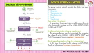
  • 1. The power system network consists the following major components:  Generator  Transmission line  Distribution line  Load  Transformer Generation: (Generator) In generation the energy is converted from one form to other forms and it voltage level be 6.6KV, 10.5KV, 11KV, 13.8KV and 15.75KV Sending end substation: (Step up transformer) The generated power can be transmitted by increasing the voltage level to 110 KV, 132KV, 220KV, 400KV and 765KV, this stage is known as primary transmission. Receiving end substation: (Step down transformer) In this stage the voltage level is reduced to 66KV, 33KV. This level is known as Secondary transmission. Structure of Power System Mr.C.Anandhakumar, AP / EEE, SRIT POWER SYSTEM ANALYSIS
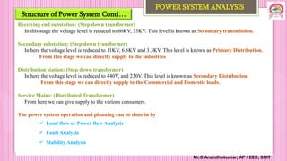
  • 2. Receiving end substation: (Step down transformer) In this stage the voltage level is reduced to 66KV, 33KV. This level is known as Secondary transmission. Secondary substation: (Step down transformer) In here the voltage level is reduced to 11KV, 6.6KV and 3.3KV. This level is known as Primary Distribution. From this stage we can directly supply to the industries Distribution station: (Step down transformer) In here the voltage level is reduced to 440V, and 230V. This level is known as Secondary Distribution. From this stage we can directly supply to the Commercial and Domestic loads. Service Mains: (Distributed Transformer) From here we can give supply to the various consumers. The power system operation and planning can be done in by  Load flow or Power flow Analysis  Fault Analysis  Stability Analysis Structure of Power System Conti… Mr.C.Anandhakumar, AP / EEE, SRIT POWER SYSTEM ANALYSIS
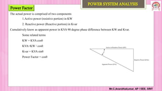
  • 3. The actual power is comprised of two components 1.Active power (resistive portion) in KW 2. Reactive power (Reactive portion) in Kvar Cumulatively know as apparent power in KVA 90 degree phase difference between KW and Kvar. Some related terms KW = KVA cosθ KVA=KW / cosθ Kvar = KVA sinθ Power Factor = cosθ Power Factor Mr.C.Anandhakumar, AP / EEE, SRIT POWER SYSTEM ANALYSIS
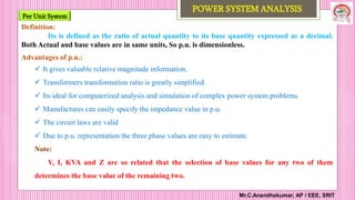
  • 4. Per Unit System Mr.C.Anandhakumar, AP / EEE, SRIT POWER SYSTEM ANALYSIS Definition: Its is defined as the ratio of actual quantity to its base quantity expressed as a decimal. Both Actual and base values are in same units, So p.u. is dimensionless. Advantages of p.u.:  It gives valuable relative magnitude information.  Transformers transformation ratio is greatly simplified.  Its ideal for computerized analysis and simulation of complex power system problems.  Manufactures can easily specify the impedance value in p.u.  The circuit laws are valid  Due to p.u. representation the three phase values are easy to estimate. Note: V, I, KVA and Z are so related that the selection of base values for any two of them determines the base value of the remaining two.
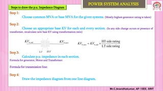
  • 11. Steps to draw the p.u. Impedance Diagram Mr.C.Anandhakumar, AP / EEE, SRIT POWER SYSTEM ANALYSIS         ï‚´         ï‚´  given b new b new b given b given u p new u p MVA MVA KV KV Z Z , , 2 , , , . , .   b b actual base actual new u p MVA KV Z Z Z Z ï‚´ ï‚´  2 , . Step 1: Choose common MVA or base MVA for the given systems. (Mostly highest generator rating is taken) Step 2: Choose an appropriate base KV for each and every section. (In any side change occurs or presence of transformer, recalculate new base KV using transformation ratio) Step 3: Calculate p.u. impedance in each section. Formula for generator, Motor and Transformer: Formula for transmission line: Step 4: Draw the impedance diagram from one line diagram. old b KV , new b KV , V L. V H. rating side LT rating side HT , , ï‚´  old b new b KV KV
  • 12. Impedance Diagram Mr.C.Anandhakumar, AP / EEE, SRIT 6/14/2024 POWER SYSTEM ANALYSIS The impedance diagram on single phase basis under balanced operating conditions can be drawn from one line diagram. 1 E 3 E 2 E 1 Z 1 T Z 1 T Z l Z l Z 2 T Z 2 T Z 2 Z 3 Z L Z Reactance Diagram 1 E 3 E 2 E 1 X 1 T X l X 2 T X 2 X L X 1 T X l X 2 T X 3 X
  • 13. Formation of Y-Bus by Two rule method or Inspection Method Mr.C.Anandhakumar, AP / EEE, SRIT POWER SYSTEM ANALYSIS Introduction:  An interconnected power system represents an electric network with a multitude of branches and nodes.  The transmission lines constitute the branches.  In some of the buses power being injected into the network (Generator Bus)  Other buses power being tapped for loads (Load Bus) Bus Matrix Classification:  Admittance Bus ( Y Bus) - Applications in Load flow and stability analysis.  Impedance Bus (Z bus) – Applications in Short Circuit analysis The above said two bus matrix find the applications in power system planning and operational studies. The injected bus currents and bus voltages of a power system under steady state condition can be regulated through these matrices as [V] [Z][I] [I] [Y][V]  
  • 14. Power Flow Analysis Mr.C.Anandhakumar, AP / EEE, SRIT 6/14/2024 POWER SYSTEM ANALYSIS Classification of buses:  Slack Bus or Ref Bus  P-V Bus or Generator Bus  P-Q Bus or Load Bus S.No Bus Quantities Specified Quantities to be specified 1. Slack bus or Ref Bus V, δ P, Q 2. P-V Bus or Generator Bus P, V Q, δ 3. P-Q Bus or Load Bus P, Q V, δ Where, P = PG - PL Q = QG – QL PG = Real power generated by generator connected to the bus. QG = Reactive power generated by generator connected to the bus. PL = Real power drawn by the load. QL = Reactive power drawn by the load.