powerfactor.pdf
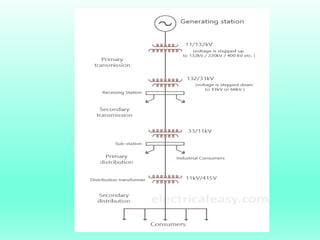
- 1. Electrical Power Supply System The conveyance of electric power from a power station to consumer,s premises is known as electrical Power supply system. An electric supply system consists of three principal components . 1-Power Station 2-Transmission lines 3-Distribution
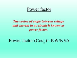
- 3. Power factor The cosine of angle between voltage and current in ac circuit is known as power factor. Power factor (Cos )= KW/KVA
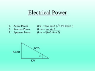
- 4. Electrical Power 1. Active Power (kw = kva cos ( 3 V I Cos ) 2. Reactive Power (kvar = kva sin 3. Apparent Power (kva = (kw2+kvar2) KVA KW KVAR
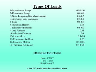
- 5. Types Of Loads 1-Incandescent Lamp 0.98-1.0 2-Flourescent Lamp 0.6-0.8 3-Neon Lamp used for advertisement 0.4-0.5 4-Arc lamps used in cienema 0.3-0.7 5-Fans 0.5-0.8 6-Induction Heaters 0.85 7-Resistance Furnaces 0.6-0.9 8-Arc Furnaces 0.85 9-Induction Furnaces 0.6 10-Arc welders 0.3-0.4 11-Resistances Welders 0.65 12-Induction Motors 0.5-0.85 13-Fractional h.p.motors 0.4-0.75 Effect of low Power Factor Heat = I*2 R T I ÎŽ to 1/ cosÃļ H ÎŽ (1/ cosÃļ)*2 A low P.F. would mean increased heat losses.
- 6. Causes of Low Power factor 1.Induction Motors 2.Arc Lamps, electrical discharge Lamps 3.Industrial Heating furnace at low lagging power factor 4.From power system.
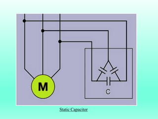
- 7. Power factor Improvement Equipment 1.Static capacitor Advantage- 1.They have low losses 2.They require little maintenance as there are no rotating parts 3.They can be easily installed as they are light and require no foundation 4.They can work under ordinary atmospheric conditions Disadvantages 1.They have short services life ranging from 8 to 10 years. 2.They are easily damaged if the voltage exceeds the rated value. 3. Once the capacitors are damaged, there repair is uneconomical.
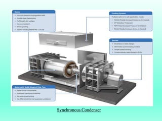
- 9. Asynchronous motor takes a leading current when over excited and ,therefore,they acts as a capacitor.An overexcited synchronous motor running on no load is known as synchronous condensor. Advantage- 1.By varying the field excitation ,the magnitude of current drawn by motor can be changed by any amount.this helps in achieving step less control of power factor. 2.The motor winding have high thermal stability to short circuit currents 3.The faults can be removed easily Disadvantages 1.There are considerable losses in the motor. 2.The maintenance cost is high. 3.It produces noise . 4.Except in sizes above 500kva ,the cost is greater than that of static capacitors of the same ratings. 5.As a synchronous motor has no self starting torque,therefore,an auxiliary equipment has to be provided for this purpose Synchronus Condensor
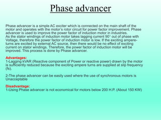
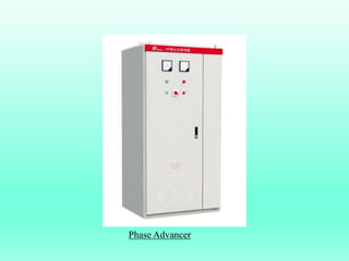
- 11. Phase advancer is a simple AC exciter which is connected on the main shaft of the motor and operates with the motorâs rotor circuit for power factor improvement. Phase advancer is used to improve the power factor of induction motor in industries. As the stator windings of induction motor takes lagging current 90° out of phase with Voltage, therefore the power factor of induction motor is low. If the exciting ampere- turns are excited by external AC source, then there would be no effect of exciting current on stator windings. Therefore, the power factor of induction motor will be improved. This process is done by Phase advancer. Advantages: 1-Lagging kVAR (Reactive component of Power or reactive power) drawn by the motor is sufficiently reduced because the exciting ampere turns are supplied at slip frequency (fs). 2-The phase advancer can be easily used where the use of synchronous motors is Unacceptable Disadvantage: 1-Using Phase advancer is not economical for motors below 200 H.P. (About 150 KW) Phase advancer
- 12. Phase Advancer
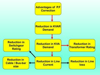
- 13. Reduction in Transformer Rating Reduction in KVAR Demand Advantages of P.F Correction Reduction in KVA Demand Reduction in Line Current Reduction in Line loss Reduction in Cable / Bus-bar size Reduction in Switchgear Rating
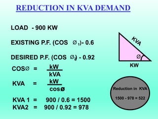
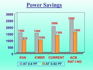
- 14. REDUCTION IN KVA DEMAND LOAD - 900 KW EXISTING P.F. (COS - 0.6 DESIRED P.F. (COS ) - 0.92 KW Ã. KVA 1 = 900 / 0.6 = 1500 KVA2 = 900 / 0.92 = 978 Ã 1) Ã2 kW kVA COS = KVA = Ã. kW cosÃ. Reduction in KVA 1500 - 978 = 522
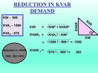
- 15. REDUCTION IN KVAR DEMAND kVA = KVAR1 = = KVAR 2 = ïKW2 + KVAR2 ïKVA1 2 - KW2 ï1500 2 - 900 2 = 1200 ï978 2 - 900 2 = 382 KW - 900 KVA1 - 1500 KVA2 - 978 KW Ã. KVAR Reduction in KVAR 1200 - 382 = 818
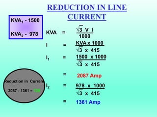
- 16. REDUCTION IN LINE CURRENT KVA = I = I1 = = I2 = = ï3 V I 1000 KVA x 1000 ï3 x 415 1500 x 1000 ï3 x 415 2087 Amp 978 x 1000 ï3 x 415 1361 Amp KVA1 - 1500 KVA2 - 978 Reduction in Current 2087 - 1361 = 726
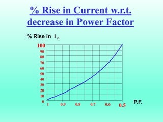
- 17. 0 10 20 30 40 50 60 70 80 90 100 1 0.9 0.8 0.7 0.6 0.5 % Rise in Current w.r.t. decrease in Power Factor % Rise in I n P.F.
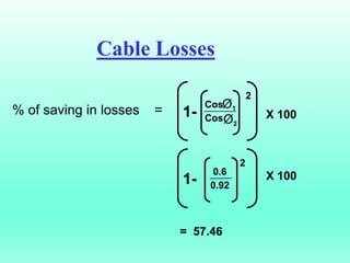
- 18. % of saving in losses = 1- Cos Cos Ã1 Ã2 2 1- 0.6 0.92 2 X 100 X 100 = 57.46 Cable Losses
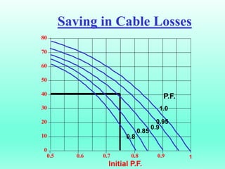
- 19. 0 10 20 30 40 50 60 70 80 0.5 0.6 0.7 0.8 0.9 1 Saving in Cable Losses P.F. 1.0 0.95 0.9 0.85 0.8 Initial P.F.
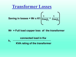
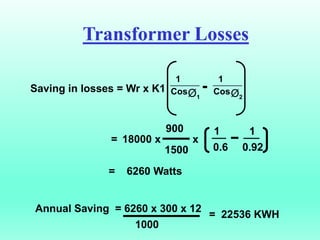
- 20. Saving in losses = Wr x K1 Wr = Full load copper loss of the transformer connected load in Kw k1 KVA rating of the transformer 1 CosÃ1 1 CosÃ2 - Transformer Losses
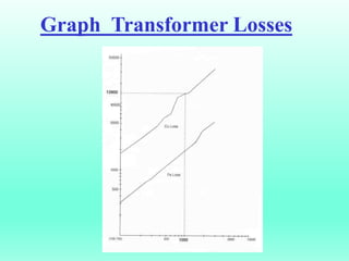
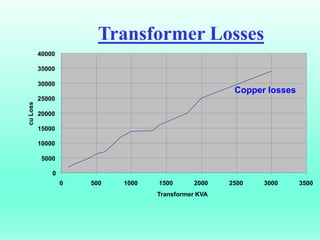
- 22. Transformer Losses 0 5000 10000 15000 20000 25000 30000 35000 40000 0 500 1000 1500 2000 2500 3000 3500 Transformer KVA cu Loss Copper losses
- 23. Transformer Losses Saving in losses = Wr x K1 1 CosÃ1 1 CosÃ2 - = 900 1500 1 1 0.6 0.92 = 6260 Watts Annual Saving = 6260 x 300 x 12 1000 = 22536 KWH 18000 x x
- 24. Power Savings KVA X'MER CURRENT ACB RAT I NG 1500 978 1500 1000 2086 1360 2500 0 500 1000 1500 2000 2500 3000 KVA X'MER CURRENT ACB AT 0.6 PF AT 0.92 PF 1600
- 25. What are the effects of harmonics on motor operation and performance? Harmonics increase motor losses, and can adversely affect the operation of sensitive auxiliary equipment. The non-sinusoidal supply results in harmonic currents in the stator which increases the total current drawn. In addition, the rotor resistance (or more precisely, impedance) increases significantly at harmonic frequencies, leading to less efficient operation. Also, stray load losses can increase significantly at harmonic frequencies. Overall motor losses increase by about 20% with a six-step voltage waveform compared to operation with a sinusoidal supply. In some cases the motor may have to be de-rated as a result of the losses. Alternatively, additional circuitry and switching devices can be employed to minimize losses. Instability can also occur due to the interaction between the motor and the converter. This is especially true of motors of low rating, which have low inertia. Harmonics can also contribute to low power factor.
- 26. Correction of Poor power factor Write some strategies for correcting poor power factor in motors? The following are strategies for correcting power factor in motors: 1. Minimise operation of idling or lightly loaded motors 2. Ensuring correct supply of rated voltage and phase balance 3. Installing capacitors to decrease reactive power loads
- 27. Capacitor rating The size of capacitor required for a particular motor depends upon the no-load reactive kVA (kVAR) drawn by the motor, which can be determined only from no-load testing of the motor. In general, for full loading operating motor, the capacitor selected to not exceed 90 % of the no-load kVAR of the motor. (Higher capacities could result in over-voltages and motor burn-outs). What is the thumb rule for installing capacitors to motor terminal? The size of capacitor required for a particular motor depends upon the no-load reactive kVA (kVAR) drawn by the motor, which can be determined only from no-load testing of the motor. In general, the capacitor is then selected to not exceed 90 % of the no-load kVAR of the motor. (Higher capacities could result in over-voltages and motor burn-outs). Alternatively, typical power factors of standard motors can provide the basis for conservative estimates of capacitor ratings to use for different size motors.
- 28. Star Connected motors Why is it beneficial to operate motors in star mode for under loaded motors? For motors which consistently operate at loads below 50 % of rated capacity, an inexpensive and effective measure might be to operate in star mode. A change from the standard delta operation to star operation involves re-configuring the wiring of the three phases of power input at the terminal box. Operating in the star mode leads to a voltage reduction by a factor of âsquare root of 3â. Motor output falls to one-third of the value in the delta mode, but performance characteristics as a function of load remain unchanged. Thus, full-load operation in star mode gives higher efficiency and power factor than partial load operation in the delta mode. However, motor operation in the star mode is possible only for applications where the torque-to-speed requirement is lower at reduced load.
- 29. Efficiency Of Electricity Name the two important parameters that attribute to efficiency of electricity use by AC induction Motors? The important parameters that attribute to efficiency of electricity use by AC induction Motors are 1. Efficiency of the motor 2. Power Factor
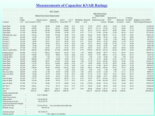
- 30. Measurements of Capacitor KVAR Ratings MCC Details Before Power Factor Improvement After Power Factor Improvement Location Line Voltag e VL Line Current IL Reactive power KVAr Apparent Power KVA Active Power KW Cos # P.F. Multipling Factor Required Kvar KVA Requiremen t Load Current Reduction In KVA Demand Reduction In current % Saving In Cable Losses Budgetry Cost of APFC Panel alongwith Reactors Paste Plant 415.00 152.00 60.00 84.00 69.00 0.75 0.74 51.02 69.70 96.97 14.30 55.03 42.61 112244.69 Paste Plant 437.80 199.80 92.14 163.47 129.84 0.83 0.53 68.75 131.15 172.96 32.32 26.84 29.71 151253.99 Paste Plant 431.00 261.00 105.00 182.00 150.00 0.82 0.56 83.33 151.52 202.97 30.48 58.03 31.39 183318.96 Paste Plant 417.00 182.00 85.50 129.00 97.00 0.75 0.74 71.72 97.98 135.66 31.02 46.34 42.61 157793.26 R/R Shift elec room 421.00 153.04 70.00 110.00 78.00 0.70 0.88 68.46 78.79 108.05 31.21 44.99 50.01 150615.34 Pot line 3 421.00 61.00 23.00 42.30 35.50 0.84 0.50 17.87 35.86 49.18 6.44 11.82 28.01 39318.97 Pot line 3 431.00 68.81 23.47 33.26 23.64 0.71 0.85 20.08 23.88 31.99 9.38 36.82 48.57 44172.53 Pot line 2 421.00 58.99 29.47 45.27 34.28 0.76 0.71 24.43 34.63 47.49 10.64 11.50 41.07 53746.69 Pot line 2 431.00 86.93 49.29 63.35 39.76 0.63 1.09 43.35 40.16 53.80 23.19 33.13 59.50 95361.83 Pot line 1 420.00 52.00 21.00 37.10 30.70 0.83 0.54 16.66 31.01 42.63 6.09 9.37 30.56 36641.60 Pot line 1 431.00 87.28 46.52 62.59 41.92 0.67 0.97 40.47 42.34 56.72 20.25 30.56 54.20 89043.13 Above G shift office 421.00 426.00 220.00 311.00 242.00 0.73 0.79 192.08 244.44 335.24 66.56 90.76 45.63 422585.41 Rodding Room 424.00 175.29 100.23 120.07 65.99 0.55 1.38 90.80 66.66 90.77 53.41 84.52 69.14 199763.32 Cathode MCC 411.00 129.00 45.50 90.00 76.50 0.86 0.45 34.69 77.27 108.55 12.73 20.45 24.71 76327.62 Cathode MCC 431.00 18.00 7.50 11.10 8.10 0.75 0.74 5.99 8.18 10.96 2.92 7.04 42.61 13176.55 Paste Plant 416.00 200.00 33.70 48.00 33.00 0.72 0.82 27.10 33.33 46.26 14.67 153.74 47.11 59630.78 Paste Plant 422.00 156.89 84.91 113.02 73.69 0.66 1.00 73.38 74.43 101.84 38.59 55.05 55.56 161435.31 Paste Plant 426.00 172.28 85.83 130.86 98.89 0.76 0.71 70.48 99.89 135.38 30.97 36.90 41.07 155046.98 Paste Plant 423.00 96.73 49.18 56.36 27.70 0.49 1.64 45.33 27.98 38.19 28.38 58.54 75.50 99730.33 Paste Plant 421.00 238.68 89.20 169.38 143.62 0.85 0.48 68.54 145.07 198.95 24.31 39.73 26.28 150794.47 B/F NO 5 431.00 7.10 4.60 5.10 2.20 0.42 2.02 4.44 2.22 2.98 2.88 4.12 82.00 9768.47 Near inst office 426.00 52.60 31.90 30.50 23.00 0.43 1.96 45.01 23.23 31.49 7.27 21.11 81.13 99029.75 Near inst office 426.00 62.40 29.70 32.60 13.20 0.41 2.06 27.14 13.33 18.07 19.27 44.33 82.51 59713.33 R/R 423.00 55.00 25.30 36.10 25.80 0.71 0.84 21.70 26.06 35.57 10.04 19.43 48.13 47729.91 Near W Shop 421.00 175.75 90.60 132.42 96.34 0.73 0.79 76.47 97.31 133.46 35.11 42.29 45.63 168230.90 Near W Shop 423.00 132.46 63.99 97.03 73.72 0.75 0.74 54.51 74.46 101.64 22.57 30.82 42.61 119922.88 Near W Shop 417.00 127.58 69.00 91.70 68.00 0.34 2.62 178.40 68.69 95.10 23.01 32.48 88.21 392470.35 B/F NO 5 427.00 128.61 57.43 83.72 63.25 0.73 0.79 50.20 63.89 86.39 19.83 42.22 45.63 110448.46 B/F NO 5 423.00 220.42 106.81 168.13 129.65 0.77 0.69 88.96 130.96 178.75 37.17 41.67 39.51 195706.61 Total 3937.63 1800.77 2679.43 1994.29 1661.37 2014.43 2748.00 665.00 1189.64 3655022.43 Present Annual KvaH Requirement = 2,34,71,806.80 After Power Factor Improvement = 1,76,46,444.85 Total Saving in KvaH = 58,25,361.95 Annual saving Kvah Charged @ Rs 4 Per Unit = 2,33,01,447.81 Two crore thirty three lakh only Monthly saving = 1941787.32 Total Investment = 36,55,022.43 Payback period = 1.88( Approx two Months)
- 31. The End Vidya Sagar vidya.sagar@adityabirla.com B.Tech Electrical (JMI Delhi) Hindalco Industries LTD. PH-9795456393

