Ppt 01 10
âĒDownload as ZIP, PDFâĒ
1 likeâĒ1,305 views

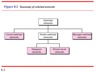
This document discusses different types of switched networks including circuit-switched, datagram, and virtual-circuit networks. In circuit switching, resources are reserved during setup and remain dedicated until teardown. Datagram networks allocate resources on demand without setup. Virtual circuits have aspects of both, reserving resources like circuits but packets may arrive out of order. The document also covers switch structures, comparing crossbar, multistage, and packet switches. Packet switches use buffers, queues, and scheduling at input and output ports.


![Note
According to the Clos criterion:
n = (N/2)1/2
k > 2n â 1
Crosspoints âĨ 4N [(2N)1/2 â 1]
8.37](https://image.slidesharecdn.com/ppt0110-121003230516-phpapp02/85/Ppt-01-10-37-320.jpg)
Ppt 01 10
- 1. Chapter 8 Switching 8.1 Copyright ÂĐ The McGraw-Hill Companies, Inc. Permission required for reproduction or display.
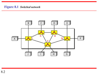
- 2. Figure 8.1 Switched network 8.2
- 3. Figure 8.2 Taxonomy of switched networks 8.3
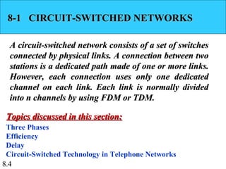
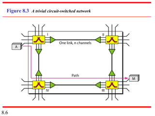
- 4. 8-1 CIRCUIT-SWITCHED NETWORKS A circuit-switched network consists of a set of switches connected by physical links. A connection between two stations is a dedicated path made of one or more links. However, each connection uses only one dedicated channel on each link. Each link is normally divided into n channels by using FDM or TDM. Topics discussed in this section: Three Phases Efficiency Delay Circuit-Switched Technology in Telephone Networks 8.4
- 5. Note A circuit-switched network is made of a set of switches connected by physical links, in which each link is divided into n channels. 8.5
- 6. Figure 8.3 A trivial circuit-switched network 8.6
- 7. Note In circuit switching, the resources need to be reserved during the setup phase; the resources remain dedicated for the entire duration of data transfer until the teardown phase. 8.7
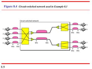
- 8. Example 8.1 As a trivial example, let us use a circuit-switched network to connect eight telephones in a small area. Communication is through 4-kHz voice channels. We assume that each link uses FDM to connect a maximum of two voice channels. The bandwidth of each link is then 8 kHz. Figure 8.4 shows the situation. Telephone 1 is connected to telephone 7; 2 to 5; 3 to 8; and 4 to 6. Of course the situation may change when new connections are made. The switch controls the connections. 8.8
- 9. Figure 8.4 Circuit-switched network used in Example 8.1 8.9
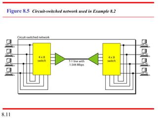
- 10. Example 8.2 As another example, consider a circuit-switched network that connects computers in two remote offices of a private company. The offices are connected using a T-1 line leased from a communication service provider. There are two 4 Ã 8 (4 inputs and 8 outputs) switches in this network. For each switch, four output ports are folded into the input ports to allow communication between computers in the same office. Four other output ports allow communication between the two offices. Figure 8.5 shows the situation. 8.10
- 11. Figure 8.5 Circuit-switched network used in Example 8.2 8.11
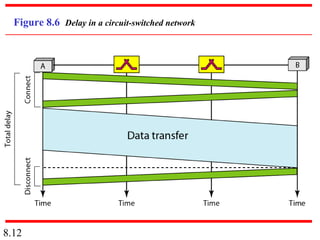
- 12. Figure 8.6 Delay in a circuit-switched network 8.12
- 13. Note Switching at the physical layer in the traditional telephone network uses the circuit-switching approach. 8.13
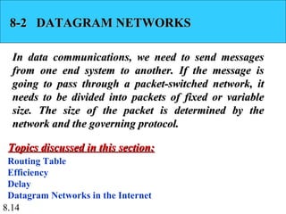
- 14. 8-2 DATAGRAM NETWORKS In data communications, we need to send messages from one end system to another. If the message is going to pass through a packet-switched network, it needs to be divided into packets of fixed or variable size. The size of the packet is determined by the network and the governing protocol. Topics discussed in this section: Routing Table Efficiency Delay Datagram Networks in the Internet 8.14
- 15. Note In a packet-switched network, there is no resource reservation; resources are allocated on demand. 8.15
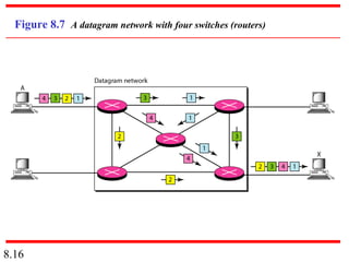
- 16. Figure 8.7 A datagram network with four switches (routers) 8.16
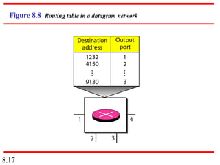
- 17. Figure 8.8 Routing table in a datagram network 8.17
- 18. Note A switch in a datagram network uses a routing table that is based on the destination address. 8.18
- 19. Note The destination address in the header of a packet in a datagram network remains the same during the entire journey of the packet. 8.19
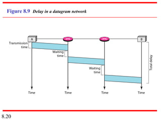
- 20. Figure 8.9 Delay in a datagram network 8.20
- 21. Note Switching in the Internet is done by using the datagram approach to packet switching at the network layer. 8.21
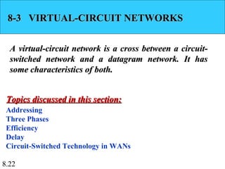
- 22. 8-3 VIRTUAL-CIRCUIT NETWORKS A virtual-circuit network is a cross between a circuit- switched network and a datagram network. It has some characteristics of both. Topics discussed in this section: Addressing Three Phases Efficiency Delay Circuit-Switched Technology in WANs 8.22
- 23. Figure 8.10 Virtual-circuit network 8.23
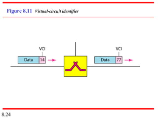
- 24. Figure 8.11 Virtual-circuit identifier 8.24
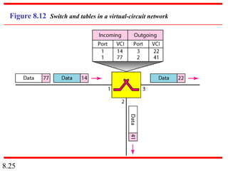
- 25. Figure 8.12 Switch and tables in a virtual-circuit network 8.25
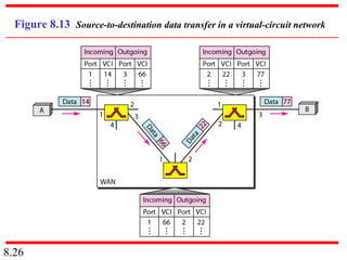
- 26. Figure 8.13 Source-to-destination data transfer in a virtual-circuit network 8.26
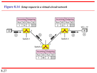
- 27. Figure 8.14 Setup request in a virtual-circuit network 8.27
- 28. Figure 8.15 Setup acknowledgment in a virtual-circuit network 8.28
- 29. Note In virtual-circuit switching, all packets belonging to the same source and destination travel the same path; but the packets may arrive at the destination with different delays if resource allocation is on demand. 8.29
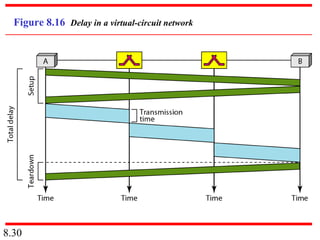
- 30. Figure 8.16 Delay in a virtual-circuit network 8.30
- 31. Note Switching at the data link layer in a switched WAN is normally implemented by using virtual-circuit techniques. 8.31
- 32. 8-4 STRUCTURE OF A SWITCH We use switches in circuit-switched and packet- switched networks. In this section, we discuss the structures of the switches used in each type of network. Topics discussed in this section: Structure of Circuit Switches Structure of Packet Switches 8.32
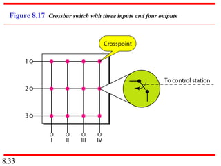
- 33. Figure 8.17 Crossbar switch with three inputs and four outputs 8.33
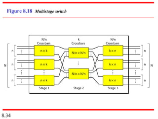
- 34. Figure 8.18 Multistage switch 8.34
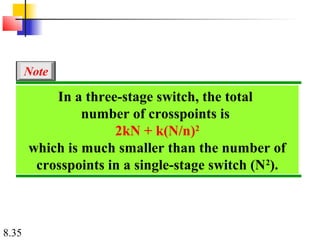
- 35. Note In a three-stage switch, the total number of crosspoints is 2kN + k(N/n)2 which is much smaller than the number of crosspoints in a single-stage switch (N2). 8.35
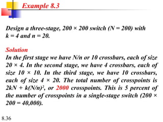
- 36. Example 8.3 Design a three-stage, 200 Ã 200 switch (N = 200) with k = 4 and n = 20. Solution In the first stage we have N/n or 10 crossbars, each of size 20 Ã 4. In the second stage, we have 4 crossbars, each of size 10 Ã 10. In the third stage, we have 10 crossbars, each of size 4 Ã 20. The total number of crosspoints is 2kN + k(N/n)2, or 2000 crosspoints. This is 5 percent of the number of crosspoints in a single-stage switch (200 Ã 200 = 40,000). 8.36
- 37. Note According to the Clos criterion: n = (N/2)1/2 k > 2n â 1 Crosspoints âĨ 4N [(2N)1/2 â 1] 8.37
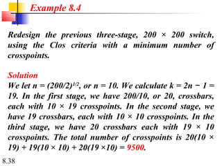
- 38. Example 8.4 Redesign the previous three-stage, 200 Ã 200 switch, using the Clos criteria with a minimum number of crosspoints. Solution We let n = (200/2)1/2, or n = 10. We calculate k = 2n â 1 = 19. In the first stage, we have 200/10, or 20, crossbars, each with 10 Ã 19 crosspoints. In the second stage, we have 19 crossbars, each with 10 Ã 10 crosspoints. In the third stage, we have 20 crossbars each with 19 Ã 10 crosspoints. The total number of crosspoints is 20(10 Ã 19) + 19(10 Ã 10) + 20(19 Ã10) = 9500. 8.38
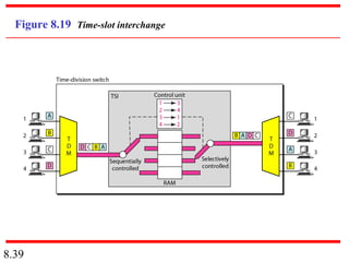
- 39. Figure 8.19 Time-slot interchange 8.39
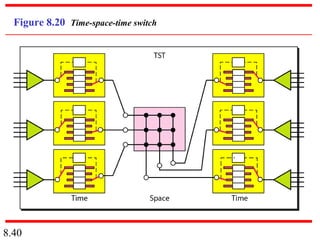
- 40. Figure 8.20 Time-space-time switch 8.40
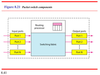
- 41. Figure 8.21 Packet switch components 8.41
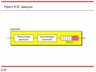
- 42. Figure 8.22 Input port 8.42
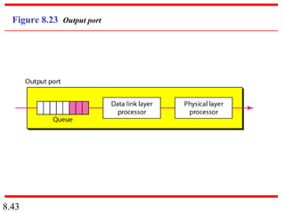
- 43. Figure 8.23 Output port 8.43
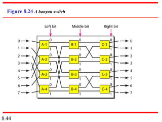
- 44. Figure 8.24 A banyan switch 8.44
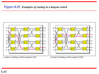
- 45. Figure 8.25 Examples of routing in a banyan switch 8.45
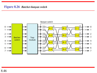
- 46. Figure 8.26 Batcher-banyan switch 8.46