The document contains several technical drawings produced by an Autodesk educational product. Each page displays geometric shapes with numerical dimensions, and includes a student name, drawing name, scale, and date in the header. The drawings were created by a student named lee2075 between October 21-25, 2010 using Autodesk design software for educational purposes.
The document contains technical drawings produced by an Autodesk educational product. Each page contains information about the student name, drawing name, scale, and date. Dimensions ranging from 0.25 to 2.75 are listed on each page. There are multiple pages showing different drawings by the same student on various dates.
The document contains a parts list and drawings for a model train assembly. It lists 9 parts needed for the train including the train body, cow catcher, smoke stack, wheels, and linkage arms. Accompanying the parts list are technical drawings with dimensions for each individual part.
The document contains 11 technical drawings created by student Koht1342 between October 18, 2010 and October 25, 2010. Each drawing page contains geometric shapes with numerical dimensions and notes that the drawing was produced with an Autodesk educational product. The title, scale, and date are provided for each technical drawing.
The document contains technical drawings with measurements created by a student named morrison2816 using Autodesk educational software. There are 7 drawings labeled and dated between October 22, 2010 and November 2, 2010 with titles like Drawing 4, Drawing 8, and Drawing 11. Each drawing page contains measurements in various scales like 1"=1' and technical shapes.
The document contains several technical drawings produced by an Autodesk educational product. The drawings include dimensions and are labeled with the student's name, drawing name, scale, and date. The drawings depict mechanical parts including a base part, linkage pieces, dowels, and parts for a crane arm and with window openings. All drawings include the label "PRODUCED BY AN AUTODESK EDUCATIONAL PRODUCT."
The document contains technical drawings for parts of a test rack, including the base of the test rack, a backplate, and screws. The drawings include dimensions, tolerances, notes and labels to fully specify the geometry and features of each part. Dimensioned orthographic and section views are provided for all parts to completely define their design and facilitate manufacturing.
The documents contain technical drawings for parts of a model train assembly, including the train body, axle pegs, linkage arms, wheels, smoke stack, and cow catcher. Dimensioned orthographic views and section views are provided for each part, along with a parts list and assembly drawing. The drawings were created by students using Autodesk design software.
The document contains several technical drawings produced by Autodesk educational software. Each page includes a technical drawing with measurements and dimensions. Below each drawing are the student name who produced it, the drawing name, scale of the drawing, and date. The drawings were created by students lee2075 and langas2053 and include designs labeled as solutions to various assignments.
The document contains 11 engineering drawings with technical specifications such as scales, dimensions, materials, dates, and student and teacher names. Each drawing page contains geometric shapes and numerical dimensions relating to an engineering part design. The drawings are labeled Part1 through Part11 and were created by a student for their T202-03 engineering class between October 21-26, 2010.
The document contains technical drawings for an axle assembly created by a student using Autodesk software. The drawings depict individual parts like the base, walls, housing and wheels at varying scales. An assembly drawing brings the parts together and lists them with quantities. The student's name, drawing name, scale and date are provided for each part and assembly print.
The document contains technical drawings and parts lists for an assembly project. It includes 5 separate drawings showing details of individual parts like bases and wheels. It also has an assembly drawing and parts list identifying the 6 different parts and their quantities needed for the overall assembly. The drawings were created by a student named depau9827 for a project called Assembly1 using Autodesk education software.
The document details the design of a shoe size 8, including diagrams of the sole, toe, heel, back strap, and front strap. The sole has three layers - a bottom tire layer, middle foam layer, and top book cover layer. The toe, heel, back strap, and front strap are made of tire, tire, dog leash, and dog leash respectively. An exploded view diagram shows the five parts of the shoe and a parts list identifies the individual pieces.
The document contains 7 technical drawings produced by an Autodesk educational product. Each drawing is labeled with the student name "lee2075", the drawing name (Part 1 through Part 7), scale of the drawing, and date. The drawings contain technical drawings of mechanical objects and parts with labeled dimensions.
This technical drawing shows various geometric shapes and measurements, including rectangles, circles, and lines of different lengths. It contains dimensions ranging from 0.50 to 4.00 units and was produced using Autodesk software. The drawing is titled "auxilarry drawing" and was created by a student named morrison2816 at a 1:2 scale on November 9, 2010.
The document contains 3 technical drawings created by students using Autodesk software. The drawings include dimensions and notes for a cow catcher, hitch magazine, and linkage arm. Key details noted are dimensions for various features of the objects ranging from 0.01 to 3.88 inches. Students' names and dates are listed for each drawing.
The document contains several engineering drawings created by students using Autodesk software. The drawings include parts for a cord flexor assembly, such as Cord Flexor Part 1-3, and a wrench. Other drawings show a collar part and section view with dimensions. Each image is labeled with the student name, drawing name, scale, and date.
The document contains 4 sections (A-A, B-B, C-C, D-D) of technical drawings at a scale of 1.5 inches to 1 inch. Each section depicts a cross section view and includes dimensions. Section information like scales, fillets, and rounds are provided for each view. The drawings were created using Autodesk software and include the student name, drawing name, scale, and date.
This document is the complete Smith chart showing the radial scaling of impedance parameters toward the load and generator. It displays resistance, conductance, and other impedance parameters scaled across the chart to enable analysis of transmission lines and matching networks.
The document is about The Complete Smith Chart by Black Magic Design. The Smith Chart is a graphical chart used in electronics to display impedance and admittance matching networks for radio frequency engineering applications. It maps the complex impedance or admittance values onto a two-dimensional chart in a way that preserves the mathematical relationships between the different impedance and admittance values.
The document contains technical drawings from a student named depau9827 created using an Autodesk educational product. There are drawings titled "Sketching problem-3" through "Sketching problem-11" dated from October 21-25, 2010 with various scales listed. The drawings appear to be practice sketches done by the student to learn technical drawing skills.
This document contains engineering drawings of cross sections for a 3D model. Section B-B shows the dimensions and features of one cross sectional view at a 1:1 scale. Section C-C shows another cross sectional view of the same 3D model with different dimensions and including rounded edges and slots. Both views are labeled with the student name, drawing name, scale, and date they were created using Autodesk design software.
The document summarizes the testing of a child-sized chair designed by Assunta and Matt. It details the surface areas and weight capacity of the chair, finds it is comfortable but may squeeze older children's hips. Possible changes are suggested to make the back interlock with sides for better stability and rocking. Hazards include potential pinching from piece movement. Aesthetically, the chair's bright colors and splatter design appeal to children.
This student analyzed various train car designs and identified elements they wanted to incorporate into their own train car design for a PLTW class project. Key elements included curved windows for views, an observation dome running the length of the car, cut-out windows, arched wheel details, balcony size and shape, vertical rail rods, thinner wheel spokes, and selectively painting different elements different colors. The goal was to create a realistic-looking toy train car that incorporated useful observation features.
This document provides tips for reusing common waste items like plastic bags, juice tetra packs, plastic bottles, and chocolate wrappers instead of throwing them directly in the trash. It encourages recycling these materials by giving examples like using plastic bottles to plant seeds, as vases, or to make toys and decorations. Recycling tetra packs and plastic bags is suggested by making cases, pouches, dress covers, and chair covers from them. The overall message is that recycling and reusing waste can help reduce littering and keep the earth cleaner and happier.
This document presents a concept for a 2-liter plastic bottle that includes an integrated cup holder and plastic cups. The bottle targets consumers who buy large bottles for travel, tailgating, family sizes, parties, and outdoor activities. It features grooves for easy removal of the cup holder. The concept proposes special event marketing of the bottle at sports events, movie releases, and through limited edition collections. The cup holder can hold up to six cups through a simple holding mechanism.
This drawing was created by K. Thorpe for Problem 19-18 on February 23, 2015 at a scale of 1:1. The drawing was created using the CCTC FILES\SEMESTER 4\SOLIDWORKS\PROBLEM 19-18.DWG file and is drawing number 1 of 1.
This document summarizes research into solutions for acquiring flow meter readings from a water feature to understand water losses. It identifies measuring flow, transmitting data wirelessly, manipulating data easily, and having a reliable, cost-effective system as key requirements. Potential solutions investigated include using a paddlewheel sensor with SD card or cellular data transmission, or a microcontroller with USB or wireless transmission. An Omega flow sensor/transmitter combined with a data logger or microcontroller is recommended to meet the requirements.
The document evaluates 5 ideas against criteria for buildable durability, safety, size, and development time. The highest scoring idea received a total of 19 points, followed by an idea with 18 points then 16 points. The lowest scoring idea received a total of 12 points.
The document appears to be a collection of technical drawings produced by a student named witt2634 using an Autodesk educational software. There are 8 pages of drawings labeled Part3 through Part8, each with technical drawings consisting of lines and measurements. Each page contains the student name, drawing name, scale, and date in the header.
This technical drawing depicts various geometric shapes such as rectangles, circles, and arcs with labeled dimensions. Key specifications include a rectangle with dimensions of 4.00 x 2.50 units, a circle with a diameter of 1.25 units, and an arc with a radius of 1.25 units within a larger rectangle. The drawing was produced by Autodesk design software for educational purposes and contains the student's name, drawing name, scale of 1:2, and date.
This technical drawing shows the dimensions of various geometric shapes including lines, circles, arcs and rectangles. Key dimensions shown are lines and arcs with lengths of 1, 1.25, 2, 2.5 and 4 units as well as a circle with a diameter of 1.25 units and rectangles with sides of 1 by 2.5 and 1.25 by 2 units. The drawing also includes information about the student name, drawing name, scale and date.
The document appears to be a technical drawing created by an Autodesk educational product. It includes various geometric shapes such as rectangles, circles, and lines with labeled dimensions. At the bottom it lists the student name, drawing name, scale, and date the drawing was produced.
This document appears to be a technical drawing created by an Autodesk educational product. The drawing includes dimensions for various lines and shapes, including rectangles and circles. At the bottom it lists the student name, drawing name, scale, and date the drawing was produced.
The document appears to be a technical drawing created by a student using Autodesk software. It includes dimensions and annotations for various shapes, such as rectangles and circles. At the bottom, it lists the student's name, the drawing name "Auxilary.ipt", a scale of 1/2, and the date of 11/5/2010.
The document contains technical drawings and diagrams for parts of a toy train, including the train body, axle pegs, and linkage arm. Dimensioned drawings show details like hole sizes and shapes. A parts list at the end identifies the main part as the train body and lists axle pegs as another part, with quantities for each.
The document contains technical drawings for parts of a model car created by a student named witt2634 using Autodesk software. The drawings include dimensions and notes for a base, two sides, two side connectors, and four wheels. A final assembly drawing shows how to assemble the seven listed parts into a complete model car.
Final title anthony_l_brian_j_cj_p_2[1]jestice7882
Ìý
The document contains technical drawings and specifications for various mechanical parts produced by Autodesk educational software, including a linkage arm, wheel, vehicle body, smokestack, and other unlabeled parts. The drawings include dimensions, tolerances, notes, and section and detail views labeled with scales. Student names and dates are provided in the title blocks.
The document shows a technical drawing with labeled dimensions of a mechanical part. Key dimensions include a length of 4.60 units on one side, widths of .84 and 1 units on another side, and various radii and depths labeled in decimal units. The drawing title is listed as "Part Be.ipt" and it is scaled at 1 inch for every 2 drawing units. It was produced by an Autodesk educational product and includes the student and date who created the drawing.
This technical drawing shows different views of a part including a front view, top view, and right side view. The front view is labeled with dimensions of 1 unit by 1.25 units, the top view shows dimensions of 1 unit by 1.75 units, and the right side view shows a dimension of 1.25 units. Student and teacher names and other identification information is labeled.
The document appears to be a technical drawing created by an Autodesk educational product. It contains geometric shapes such as lines and circles with various measurements. A title block provides the student name, drawing name, scale, and date the drawing was produced.
The document contains technical drawings for three projects - a pallet, 2 liter bottle, and eco project assembly - created by a student using Autodesk educational software. Each drawing page displays the student name, drawing name, scale, and date. All drawings are labeled as having been produced by Autodesk educational software.
Cj anthony old assembly inventor and presentaion drawingscgymnast7
Ìý
The document contains several technical drawings produced by Autodesk educational software. The drawings include detailed measurements and views of mechanical parts and assemblies such as blocks, plates, racks, screws, and boxes. Each page displays the student name, drawing name, scale, and date. The drawings provide precise specifications and dimensional information for various mechanical components.
The document contains technical drawings and parts lists for an assembly project. It includes 6 separate drawings showing the details of individual parts like bases, rods and wheels. It also has an assembly drawing and parts list identifying the 6 different parts and their quantities needed for the overall assembly. The student name and dates are listed for each technical drawing.
This document contains a technical drawing with dimensions and specifications for an assembly consisting of two axles (A and B) connected by bolts. The assembly includes two M16 bolts that are 2 inches long and connect the axles, with axle A measuring 6.3 inches and axle B measuring 5 inches. Tolerances and title block information such as the date, author, and scale are provided.
The document contains technical drawings of various mechanical parts with labeled dimensions. It includes an orthographic projection of the parts with section views cut through them. The drawings were created with Autodesk software by a student for a class project and include the student name, drawing name, scale, and date.
The document contains drawings of various sports courses and equipment created by students using Autodesk software. There are drawings of a baseball course, diamond, and pitcher's mound; a croquet course and balls; a gymnastics course and beam; a polo course and water polo ball; letters; pool balls; a pool course; track grass; hurdles; and an assembly drawing of a pool course with parts list. The drawings include dimensions, notes, and were produced by Autodesk educational software.
The document summarizes research about providing shelter for those affected by the 2010 earthquake in Haiti. It provides background on Haiti's geography and climate. It then discusses the urgent need for shelter, as many buildings were destroyed. It reviews various proposed shelter solutions but notes they are often expensive or cannot be produced quickly enough. It proposes designing a temporary shelter that is inexpensive, portable, and made of recycled materials to better meet Haiti's needs.
The document summarizes research about Haiti, including its location, terrain, climate, population, and the devastating 2010 earthquake. It discusses Haiti's urgent need for shelters, as 30% of the capital was destroyed and 1.5 million people were left homeless. Current shelter solutions are described as expensive or unable to meet demand. The problem of providing affordable temporary shelters at scale is selected for further exploration, with the goal of using recycled materials for a foldable, portable design that protects against weather.
The document summarizes research about shelter needs in Haiti after the 2010 earthquake. It provides background on Haiti's geography and climate. It then discusses how the earthquake destroyed much of the housing stock and left over 1.5 million people homeless. It reviews several existing shelter solutions but notes they are expensive to implement at scale. It proposes designing an inexpensive, portable shelter made of recycled materials that can house many Haitians and protect them from storms.
This document appears to be a student's decision matrix template for a school project. It contains a table with categories like complexity, development time, safety, and size. There are three potential ideas being evaluated, with scores from 1 to 3 in each category and a total score. The categories are ranked from worst to best.
This document is a technical drawing created by a student named Haewook Lee using Autodesk educational software. It includes the drawing name, scale, date, and a repeated statement that it was produced using Autodesk educational software. Dimensions and labels are provided for various lines and shapes in the technical drawing.
Activity2 1 5_cad_model_features-- tony sorrentino and hae wookhw0830
Ìý
This document describes an activity to learn common 3D modeling features in CAD software. It includes 19 exercises to utilize features like extrusions, patterns, holes, fillets, and more. Students are instructed to open CAD files for each exercise, use the specified features, and export images of their work. Common features covered include mid-plane extrusions, tapered extrusions, revolves, holes, lofts, patterns, shells, ribs, sweeps, coils, threads, fillets, chamfers, mirrors, embossing, and decals. The goal is to understand how each feature works and gain experience using the modeling tools.
The document shows a technical drawing with labeled dimensions of a mechanical part. The drawing includes views of the part from different angles with labeled radii and rectangular features. It also contains title blocks with the student's name, drawing name, scale, and date.
The document contains technical drawings and parts lists for an assembly created by student lee2075 using Autodesk software. It includes 5 separate drawings titled Part 1 through Part 5 created on October 8, 2010 at a scale of 1 inch = 1 inch. It also includes an assembly drawing titled Assembly created on October 14, 2010 with varying scales bringing all 5 parts together. The final page lists the parts with their quantities as Part 1 (1), Part 2 (2), Part 3 (3), Part 4 (4), and Part 5 (5).
This document contains statistics related to the length of blocks in a cube. It provides the mean, median, mode, range, and standard deviation of the block lengths. It also includes a frequency table showing the number of blocks that fall within certain length bins.
Automobiles were invented by Karl Benz in 1885 when he introduced the Motorwagen, the first three-wheeled car powered by a gasoline engine. Since then, cars have been made entirely of steel, added safety features like seatbelts and airbags, and new technologies like hybrid engines. While automobiles have improved mobility, they have also negatively impacted the environment through air pollution and greenhouse gas emissions and require vast amounts of resources.
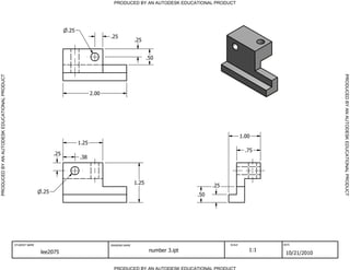
1. PRODUCED BY AN AUTODESK EDUCATIONAL PRODUCT
.25
.25
.25
.50
PRODUCED BY AN AUTODESK EDUCATIONAL PRODUCT
2.00
1.00
1.25
.75
.25
.38
1.25
.25
.25
.50
STUDENT NAME DRAWING NAME SCALE DATE
lee2075 number 3.ipt 1:1
10/21/2010
PRODUCED BY AN AUTODESK EDUCATIONAL PRODUCT
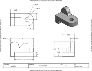
2. PRODUCED BY AN AUTODESK EDUCATIONAL PRODUCT
R.50
.25
PRODUCED BY AN AUTODESK EDUCATIONAL PRODUCT
.25
2.50
.25
1.00
1.25
R1.00
1.50
STUDENT NAME DRAWING NAME SCALE DATE
lee2075 number 4.ipt 1:1
10/22/2010
PRODUCED BY AN AUTODESK EDUCATIONAL PRODUCT
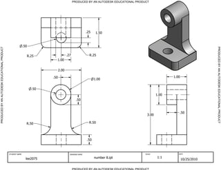
3. PRODUCED BY AN AUTODESK EDUCATIONAL PRODUCT
.50
R.75
1.25
.75
PRODUCED BY AN AUTODESK EDUCATIONAL PRODUCT
.75
1.50
R.50 2.75 .50
R.25
1.75
1.00
.50
2.25
STUDENT NAME DRAWING NAME SCALE DATE
lee2075 number 7.ipt 1:1
10/22/2010
PRODUCED BY AN AUTODESK EDUCATIONAL PRODUCT
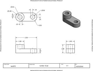
4. PRODUCED BY AN AUTODESK EDUCATIONAL PRODUCT
.25 1.50
.50
PRODUCED BY AN AUTODESK EDUCATIONAL PRODUCT
R.25 .27 R.25
1.00
2.00
.50 1.00
1.00
.50
1.00
.50
.50
3.00
R.50 R.50
.50
STUDENT NAME DRAWING NAME SCALE DATE
lee2075 number 8.ipt 1:1
10/25/2010
PRODUCED BY AN AUTODESK EDUCATIONAL PRODUCT
5. PRODUCED BY AN AUTODESK EDUCATIONAL PRODUCT
.50
.25 .50
1.00
.25
.25
PRODUCED BY AN AUTODESK EDUCATIONAL PRODUCT
.25
R.50
2.50
1.00 1.00
1.00
.50
STUDENT NAME DRAWING NAME SCALE DATE
lee2075 number 10.ipt 1:1
10/25/2010
PRODUCED BY AN AUTODESK EDUCATIONAL PRODUCT
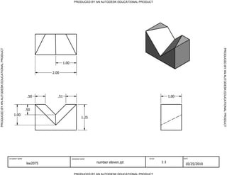
6. PRODUCED BY AN AUTODESK EDUCATIONAL PRODUCT
PRODUCED BY AN AUTODESK EDUCATIONAL PRODUCT
1.00
2.00
.50 .51 1.00
.50
1.00
1.25
STUDENT NAME DRAWING NAME SCALE DATE
lee2075 number eleven.ipt 1:1
10/25/2010
PRODUCED BY AN AUTODESK EDUCATIONAL PRODUCT