Presentation 4 mudlogging
- 1. OPERATIONS GEOLOGY PRESENTATIONS Presentation 4: Basic Mudlogging 14 October 2016Ali Trichelli
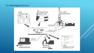
- 2. Legend ï Introduction ï Inside the Mudlogging Unit ï Main Mudlogging Services ï Major Responsibilities of the Mudloggers ïž Lag Time Determination ï Typical Monitored Parameters ï Standard Mudlogging Sensors ï The Gas System ï Real Time Data Display & Transmission ï Deliverables of the Mudlogging Contractor ï Issues with Mudlogging
- 3. Introduction ï Mud logging is a standard practice during drilling operations and is important for documenting the geology of a well. ï Drilling mud and drill bit cuttings from the formation are evaluated and their properties recorded on a mudlog as a visual analytical tool. Preserving and storing the rock cuttings and mud samples is normal procedure. ï From the cuttings, an oil stain or odor may be detected and becomes an excellent qualitative indicator. ï Continuous record of drilling parameters (penetration rate ROP, weight on bit WOB, rotation per minute RPM, torque, etcâĶ) and hydrocarbon shows is also provided.
- 4. Inside the Mudlogging Unit
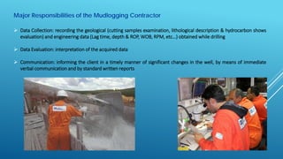
- 6. Major Responsibilities of the Mudlogging Contractor ï Data Collection: recording the geological (cutting samples examination, lithological description & hydrocarbon shows evaluation) and engineering data (Lag time, depth & ROP, WOB, RPM, etcâĶ) obtained while drilling ï Data Evaluation: interpretation of the acquired data ï Communication: informing the client in a timely manner of significant changes in the well, by means of immediate verbal communication and by standard written reports
- 8. Typical Drilling Parameters Monitored by the Mudlogging Contractor
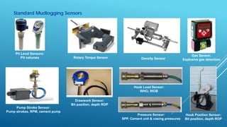
- 9. Standard Mudlogging Sensors Drawwork Sensor: Bit position, depth ROP Hook Position Sensor: Bit position, depth ROP Pump Stroke Sensor: Pump strokes, RPM, cement pump Hook Load Sensor: WHO, WOB Rotary Torque Sensor Pressure Sensor: SPP, Cement unit & casing pressures Gas Sensor: Explosive gas detection Pit Level Sensors: Pit volumes Density Sensor
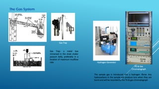
- 10. The Gas System TG & Gas Chromatograph Gas Trap Hydrogen Generator Gas Trap: a metal box immersed in the shale shaker possum belly, preferably in a location of maximum mudflow rate The sample gas is introduced into a hydrogen flame. Any hydrocarbons in the sample will produce ions when they are burnt and will be recorded by the TG & gas chromatograph
- 11. Real Time Data Display & Transmission
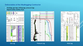
- 12. Deliverables of the Mudlogging Contractor ï Mudlogs, gas logs, drilling logs, pressure logs ï Reports (daily, weekly, final) Gas Log Pressure Log Mud Log
- 13. Issues ï The depth that the rock cuttings originated from is not always 100% accurate. Calculations can be made that determine the time it takes for the drill cutting to reach the surface, this is called âlag timeâ. Some assumption have to be made in the calculations because not all rock cuttings are the same size and density and the hole may not be gauged so there can be some error in calculating the depth that the cuttings originated from. ï A small degree of mixing occurs in the mud before it reaches the surface, so the rock cuttings in a particular sample may a mixture of cuttings from a range of depths. ï Contamination can sometimes be a problem when making interpretations of samples. There can be metal contaminates in the drilling mud from fragments of the drill bit or drill string. Cement from well casings may get into the drilling mud. Sometimes different materials may be mixed into the drill mud to help loss of circulation and these can sometimes be misinterpreted as mica flakes, calcium carbonate, or various other minerals.
- 14. Next Presentation ï Drilling Mud ïž Drilling Mud Circulating System ïž Drilling Mud Types ïž Drilling Mud Functions ïž Drilling Mud Properties & Additives ïž Drilling Mud Tests


