Project 17 Smart Home Assembly Tutorial.pdf
ŌĆó
0 likesŌĆó9 views

The document provides step-by-step instructions for assembling a smart home kit. It describes 18 steps for fixing various components like boards, sensors and modules to wood boards using screws, nuts and other hardware. Instructions include fixing servo motors, LED modules, an LCD display, temperature sensor and more. Wiring is to be done according to the provided circuit diagram.


Project 17 Smart Home Assembly Tutorial.pdf
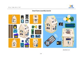
- 1. http://www.zhiyi.ltd/ 1/19 Smart home assembly tutorial 202107015 V1.0
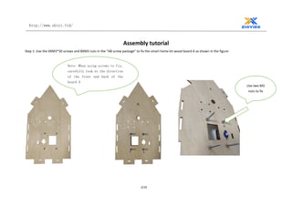
- 2. http://www.zhiyi.ltd/ 2/19 Assembly tutorial Step 1: Use the 4XM3*30 screws and 8XM3 nuts in the "AB screw package" to fix the smart home kit wood board A as shown in the figure: Use two M3 nuts to fix Note: When using screws to fix, carefully look at the direction of the front and back of the board A
- 3. http://www.zhiyi.ltd/ 3/19 Step 2: Use 2X M2*16 round head screws and 2X M2 nuts to fix the G90 servo as shown in the figure:
- 4. http://www.zhiyi.ltd/ 4/19 Step 3: Fix the steering gear rotating bracket and B gear as shown in the figure:
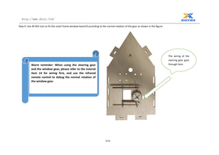
- 5. http://www.zhiyi.ltd/ 5/19 Step 4: Use 4X M3 nuts to fix the smart home window board B according to the normal rotation of the gear as shown in the figure: The wiring of the steering gear goes through here Warm reminder: When using the steering gear and the window gear, please refer to the tutorial item 14 for wiring first, and use the infrared remote control to debug the normal rotation of the window gear.
- 6. http://www.zhiyi.ltd/ 6/19 Step 5: Use 4X M3*12 flat head screws to fix the LED module. Here you need to lock four nuts first
- 7. http://www.zhiyi.ltd/ 7/19 Step 6: 2 X M2*10 round head screws; 2 X M2 nuts to fix the touch module, as shown in the figure:
- 8. http://www.zhiyi.ltd/ 8/19 Step 7: Use 2 x M3*12 flat-head screws and 2 X M3 nuts in the "C screw package" to fix the LED module. Warm reminder: When using screws to fix the LED module, pay attention to the front and back of the board.
- 9. http://www.zhiyi.ltd/ 9/19 Step 8: Fix the RGB module and the relay module with 6 x M3*12 flat head screws; 6 x nuts respectively. Use 2 X M2*10 round head screws and 2 X M2 nuts to fix the buzzer module as shown in the figure: Warm reminder: When using screws to fix, pay attention to the front and back of the board.
- 10. http://www.zhiyi.ltd/ 10/19 Step 9: Use the "DE screw pack" 4 X M3*10 flat head screws and 4 X M3 nuts; fix the small hinge with the wood board E and wood board D; as shown in the figure: Warm reminder: When using screws to fix, pay attention to the front and back of the board.
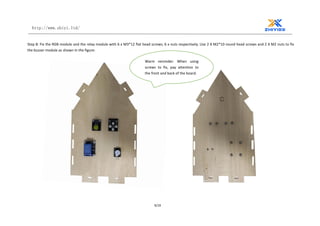
- 11. http://www.zhiyi.ltd/ 11/19 Step 10: Use the "DE screw pack" 2X M2*16 round head screws and 2X M2 screws to fix the G90 servo; at the same time use 2X M3*10+6 single-pass hexagonal copper pillars and 2 X M3*8 round head screws, 2 X M3 nut fixes the RFID module; as shown in the figure: Warm reminder: When using screws to fix, pay attention to the front and back of the board.
- 12. http://www.zhiyi.ltd/ 12/19 Step 11: Use the "F screw pack" 4 X M3*12 flat head screws and 4 X M3 nuts to fix the LCD 1602 display module. Warm reminder: When using screws to fix, pay attention to the front and back of the board.
- 13. http://www.zhiyi.ltd/ 13/19 Step 12: Use 2X M2*10 round head screws and 2X M2 nuts to fix the DHT11 temperature and humidity module. Warm reminder: When using screws to fix, pay attention to the front and back of the board.
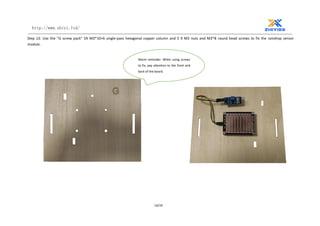
- 14. http://www.zhiyi.ltd/ 14/19 Step 13: Use the "G screw pack" 5X M3*10+6 single-pass hexagonal copper column and 5 X M3 nuts and M3*8 round head screws to fix the raindrop sensor module. Warm reminder: When using screws to fix, pay attention to the front and back of the board.
- 15. http://www.zhiyi.ltd/ 15/19 Step 14: Use "H screw pack" 4 X M3*10+6 single-way hexagonal copper posts and M3*10 screws, 4 X M3 nuts to fix the MQ-2 gas sensor module; 2 X M2*10 round head screws, 2 X M2 nut installs and fixes the infrared receiver module. Warm reminder: When using screws to fix, pay attention to the front and back of the board.
- 16. http://www.zhiyi.ltd/ 16/19 Step 15: Use 4 X M3*12 round head screws and 4 X M3 nuts to install and fix the fan module.
- 17. http://www.zhiyi.ltd/ 17/19 Step 16: Use the "L screw pack" 4 X M3*12 flat head screws, 4 X M3 nuts to fix the battery box; at the same time, use 4 X M3*10+6 single-pass hexagonal copper posts, 4 X M3*8 screws, 4 X M3 nut fixes the arduino nano expansion board. Step 17: Wiring according to the following circuit diagram. Expansion board G means GND; expansion board V means VCC; expansion board S means the pin number corresponding to arduino. (Note: the V corresponding to the red line node connection represents the VCC corresponding to the connection pin number; the black line node connection corresponding to the G represents the GND corresponding to the connection pin number)
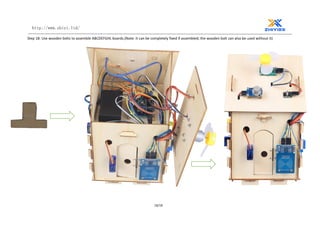
- 19. http://www.zhiyi.ltd/ 19/19 Step 18: Use wooden bolts to assemble ABCDEFGHL boards.(Note: It can be completely fixed if assembled; the wooden bolt can also be used without it)