Project eprom progr
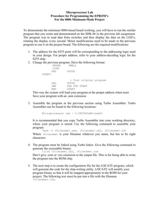
- 1. Microprocessor Lab Procedure for Programming the EPROM’s For the 8086 Minimum-Mode Project To demonstrate the minimum 8086-based board working, you will have to run the similar program that you wrote and demonstrated on the SDK-86 in the previous lab assignment. The program was to read data from switches and then display the data on the LED’s, rotating the display every second. Minor modifications need to be made to the previous program to run it on the project board. The following are the required modifications: 1. The address for the 8255 ports will be corresponding to the addressing logic used in your design. For proper address, refer to your address-decoding logic for the 8255 chip. 2. Change the previous program. Have the following format: .MODEL SMALL .CODE ORG 0000H START: ; Your original program ORG 0FF0H JMP FAR PTR START END START This way the system will load your program at the proper address when reset. Save your program with an .asm extension. 3. Assemble the program in the previous section using Turbo Assembler. Turbo Assembler can be found in the following locations: Microprocessor lab - C:MICROLABtasm31 It is recommended that you copy Turbo Assembler into your working directory, where your program is stored. Use the following command to assemble your program: Tasm -l (filename).asm, (filename).obj, (filename).lst Where (filename) is your filename whatever you name, but has to be eight characters. 4. The program must be linked using Turbo linker. Give the following command to generate the executable binary: tlink (filename).obj, (filename).rom Don’t give .com or .exe extension to the output file. This is for being able to write the program into the ROM chip. 5. The next step is to create the configuration file for the LOCATE program, which will generate the code for the chip-writing utility. LOCATE will modify your program binary so that it will be mapped appropriately to the ROM for your project. The following text must be put into a file with the filename (filename).cfg.
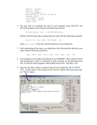
- 2. hexfile intel86 absfile axe86 listfile segments map 0xff000 to 0xfffff as rdonly cputype i8086 class DATA = 0x0000 class CODE = 0xff00 output CODE 6. The next step is to generate the code of your program using LOCATE. The LOCATE program can be found in the following locations: Microprocessor lab - C:MICROLABLocate Switch to the directory above and generate the code with the following command: Locate -Hi your path (filename) .rom where {your path} is the drive and the directory of your (filename). 7. After performing all the steps, you should have the following files that have your name with the following extensions: .asm, .obj, .axe, .lst, .cfg, .hex, .map, .rom, .loc 8. Your program is now ready to be placed on your EPROM’s. This is done by MCT chip programmer, which is connected to each computer in the Microprocessor Lab. To start the utility program, either double click on the “Top Max” icon . 9. Once the Top Max window is opened check if it has loaded the file of INTEL 2716 , if it has not(or to be sure) go to the "Device" option of the main menu and use "Select" option.
- 3. 10. After clicking on the "Select" option you find a new window prompting to enter the NAME of the file(Manufacturer Name).Enter "INTEL" and select 2716 as the device. Press "OK". 11. Perform blank check from the main menu buttons. If you get the message “Blank check ok” then proceed to the following steps. 12. Go to "Config" option of the main menu and select "Option" and set the default buffer value as ‘FF’ as shown in the figure below.
- 4. 13. In Gang Split option select"1Gang" and "Even" for even address programming. 14. Make sure that for loading the Program keep the Buffer Start and End addresses are the same as shown in the figure below.
- 5. 15. For “Auto Inc” option keep the keep the start and end address as shown in the figure below. 16. Click on "File" of the main menu and select "Load" to load the Hex file of your program into the Programmers Buffer. 17. To verify go to "Buffer" of the main menu and click on the "Edit Buffer" and check if the program code bytes are on the correct address.(starting from 0f000) 18. Close the window and select the “Program” button to start programming. 19. Similarly select “Odd” for odd address programming and follow the above (Step No.17 & 18) procedure. 20. If you don’t receive any error, you have successfully loaded your program to the EPROMs. If you get errors, first check if your EPROM is blank then exchange your EPROM at the electronics shop. Also check with the TA if you have further problems. 21. To make sure the program code bytes of the Programmed EPROMs are valid, perform a “Read” operation by first clearing off the contents of the buffer.


