


More Related Content
Similar to pulse and digital circuits file dadadesd (20)
Recently uploaded (20)


pulse and digital circuits file dadadesd
- 1. East Africa University DEPARTMENT OF ELECTRONICS AND COMMUNICATION ENGINEERING SUBJECT NAME: PULSE & DIGITAL CIRCUITS LECTURER NAME: Abdulkadir. M . Daar
- 2. PULSE & DIGITAL CIRCUITS COURSE OBJECTIVES: The student will be made ’āśTo understand the concept of wave shaping circuits, Switching Characteristics of diode and transistor. ’āśTo study the design and analysis of various Multivibrators. ’āśTo understand the functioning of different types of time- base Generators.
- 3. UNIT I LINEAR WAVESHAPING- High pass, low pass RC circuits, their response for sinusoidal, step, pulse, square and ramp inputs. RC network as differentiator and integrator, attenuators, its applications in CRO probe, RL and RLC circuits and their response for step input, Ringing circuit. UNIT II NON-LINEAR WAVE SHAPING- Diode clippers, Transistor clippers, clipping at two independent levels, Comparators, applications of voltage comparators, clamping operation, clamping circuits taking source and diode resistances into account clamping circuit theorem , practical clamping circuits, effect of diode characteristics on clamping voltage, Synchronized clamping PULSE & DIGITAL CIRCUITS
- 4. UNIT III SWITCHING CHARACTERISTICS OF DEVICES- Diode as a switch, piecewise linear diode characteristics, Transistor as a switch, Break down voltage consideration of transistor, saturation parameters of Transistor and their variation with temperature, Design of transistor switch, transistor-switching times. Silicon controlled switch circuits. UNIT IV MULTIVIBRATORS- Analysis and Design of Bistable, Monostable, Astable Multivibrators and Schmitt trigger using transistors. UNIT V TIME BASE GENERATORS- General features of a time base signal, methods of generating time base waveform, Miller and Bootstrap time base generators ŌĆō basic principles, Transistor miller time base generator, Transistor Bootstrap time base generator, Current time base generators. Methods of linearity improvement. PULSE & DIGITAL CIRCUITS
- 5. MODULE-I: Linear wave shaping CONTENTS: ’āś High pass RC circuits with Step, Pulse, Square wave and Ramp inputs ’āś Low pass RC circuits with Step, Pulse, Square wave and Ramp inputs ’āś High pass RC circuit as Differentiator ’āś Low pass RC circuit as Integrator OUTCOMES: ’āśTo derive the response of high-pass and low-pass RC circuits to different types of inputs like Sinusoidal, pulse, step, square, ramp signals. ’āśTo describe the application of high pass and low pass circuit as Differentiator and integrator respectively.
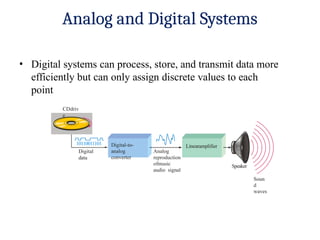
- 6. Analog and Digital Systems ŌĆó Digital systems can process, store, and transmit data more efficiently but can only assign discrete values to each point CDdriv e 10110011101 Digital data Analog reproduction ofmusic audio signal Speaker Soun d waves Digital-to- analog converter Linearamplifier
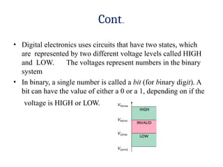
- 7. Cont.. ŌĆó Digital electronics uses circuits that have two states, which are represented by two different voltage levels called HIGH and LOW. The voltages represent numbers in the binary system ŌĆó In binary, a single number is called a bit (for binary digit). A bit can have the value of either a 0 or a 1, depending on if the voltage is HIGH or LOW.
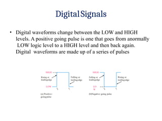
- 8. DigitalSignals ŌĆó Digital waveforms change between the LOW and HIGH levels. A positive going pulse is one that goes from anormally LOW logic level to a HIGH level and then back again. Digital waveforms are made up of a series of pulses Falling or leadingedge (b)NegativeŌĆōgoing pulse HIGH Rising or trailingedge LO W (a) PositiveŌĆō goingpulse HIGH Rising or leadingedge Falling or trailingedge LOW t0 t1 t0 t1
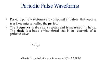
- 10. Periodic Pulse Waveforms ŌĆó Periodic pulse waveforms are composed of pulses that repeats in a fixed interval called the period. ŌĆó The frequency is the rate it repeats and is measured in hertz. The clock is a basic timing signal that is an example of a periodic wave. What is the period of a repetitive wave if f = 3.2 GHz?
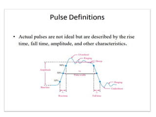
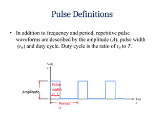
- 11. Pulse Definitions ŌĆó In addition to frequency and period, repetitive pulse waveforms are described by the amplitude (A), pulse width (tW) and duty cycle. Duty cycle is the ratio of tW to T. Volt s Pulse width (tW) Tim e Period, T Amplitude
- 12. LINEAR WAVESHAPING Linear elements such as resistors, capacitors and inductors are employed to shape a signal in this linear wave shaping. A Sine wave input has a sine wave output and hence the non-sinusoidal inputs are more prominently used to understand the linear wave shaping.
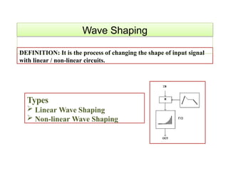
- 13. DEFINITION: It is the process of changing the shape of input signal with linear / non-linear circuits. Wave Shaping Types ’āś Linear Wave Shaping ’āś Non-linear Wave Shaping
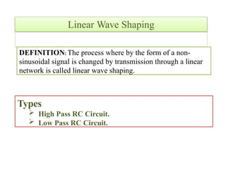
- 14. DEFINITION: The process where by the form of a non- sinusoidal signal is changed by transmission through a linear network is called linear wave shaping. Linear Wave Shaping Types ’āś High Pass RC Circuit. ’āś Low Pass RC Circuit.
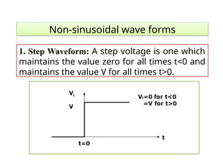
- 15. Non-sinusoidal wave forms 1. Step Waveform: A step voltage is one which maintains the value zero for all times t<0 and maintains the value V for all times t>0.
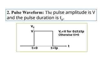
- 16. 2. Pulse Waveform: The pulse amplitude is V and the pulse duration is tp.
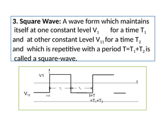
- 17. 3. Square Wave: A wave form which maintains itself at one constant level V1 for a time T1 and at other constant Level V11 for a time T2 and which is repetitive with a period T=T1+T2 is called a square-wave.
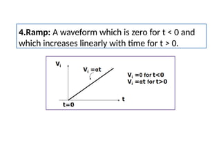
- 18. 4.Ramp: A waveform which is zero for t < 0 and which increases linearly with time for t > 0.
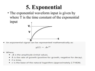
- 19. 5. Exponential 0 t ŌĆó The exponential waveform input is given by where T is the time constant of the exponential input Vi V