Rectifiers
- 1. ARJUN COLLEGE OF TECHNOLOGY AND SCIENCES
- 2. what is rectifier? A rectifier is an electrical device composed of one or more diodes that converts alternating current (AC) to direct current (DC). A diode is like a one-way valve that allows an electrical current to flow in only one direction. This process is called rectification.
- 3. German physicist Ferdinand Braun, a 24-year old graduate of the University of Berlin, studied the characteristics of electrolytes and crystals that conduct electricity at WÞrzburg University in 1874. When he probed a galena crystal (lead sulfide) with the point of a thin metal wire, Braun noted that current flowed freely in one direction only. He had discovered the rectification effect at the point of contact between metals and certain crystal materials. HISTORY Braun demonstrated this semiconductor device to an audience at Leipzig on November 14, 1876, but it found no useful application until the advent of radio in the early 1900s when it was used as the signal detector in a "crystal radio" set. (1901 Milestone) The common descriptive name "cat's-whisker" detector is derived from the fine metallic probe used to make electrical contact with the crystal surface. Braun is better known for his development of the cathode ray tube (CRT) oscilloscope in 1897, known as the "Braun tube" (Braunschweig Rohr) in German. He shared the 1909 Nobel Prize with Guglielmo Marconi for his "contributions to the development of wireless telegraphy," mainly the development of tunable circuits for radio receivers. Electronic devices that perform rectification are called diodes. Working in Thomas Edison's laboratory in 1883 William J. Hammer noted this rectifier effect when he added another electrode to a heated filament light bulb. In 1904, John Fleming patented a one-way "oscillation valve" based on the, so called, "Edison effect" that converted alternating radio signal currents into direct currents in the earphones or speaker. Known today as a diode, the Fleming valve was the first practical electronic device. The Braun point- contact rectifier diode performs the same function using semiconducting rather than thermionic properties.
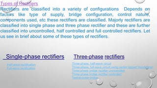
- 4. Types of Rectifiers Rectifiers are classified into a variety of configurations Depends on factors like type of supply, bridge configuration, control nature, components used, etc these rectifiers are classified. Majorly rectifiers are classified into single phase and three phase rectifier and these are further classified into uncontrolled, half controlled and full controlled rectifiers. Let us see in brief about some of these types of rectifiers. Single-phase rectifiers Three-phase rectifiers Three-phase, half-wave circuit Three-phase, full-wave circuit using center-tapped transformer Three-phase bridge rectifier uncontrolled Three-phase bridge rectifier controlled Twelve-pulse bridge Half-wave rectification Full-wave rectification
- 6. Single-phase rectifiers Half-wave rectification Full-wave rectification
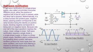
- 7. Half-wave rectification In half-wave rectification of a single-phase supply, also called uncontrolled one-pulse midpoint circuit, either the positive or negative half of the AC wave is passed, while the other half is blocked. Mathematically, it is a ramp function (for positive pass, negative block): passing positive corresponds to the ramp function being the identity on positive inputs, blocking negative corresponds to being zero on negative inputs. Because only one half of the input waveform reaches the output, mean voltage is lower. Half-wave rectification requires a single diode in a single-phase supply, or three in a three- phase supply. Rectifiers yield a unidirectional but pulsating direct current; half-wave rectifiers produce far more ripple than full- wave rectifiers, and much more filtering is needed to eliminate harmonics of the AC frequency from the output.
- 8. The no-load output DC voltage of an ideal half-wave rectifier for a sinusoidal input voltage is Vdc, Vav â the DC or average output voltage, Vpeak, the peak value of the phase input voltages, Vrms, the (RMS) value of output voltage.
- 10. Full-wave rectification A full-wave bridge rectifier converts the whole of the input waveform to one of constant polarity (positive or negative) at its output. Mathematically, this corresponds to the absolute value function. Full-wave rectification converts both polarities of the input waveform to pulsating DC (direct current), and yields a higher average output voltage. Two diodes and a center tapped transformer, or four diodes in a bridge configuration and any AC source (including a transformer without center tap), are needed.[3]Single semiconductor diodes, double diodes with common cathode or common anode, and four- diode bridges, are manufactured as single components
- 11. The average and RMS no-load output voltages of an ideal single-phase full-wave rectifier are: Very common double-diode . rectifier vacuum tubes contained a single common cathode and two anodes inside a single envelope, achieving full-wave rectification with positive output. The 5U4 and 5Y3 were popular examples of this configuration-
- 13. Three-phase rectifiers Three-phase, half-wave circuit Three-phase, full-wave circuit Three-phase bridge rectifier controlled Twelve-pulse bridge
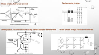
- 14. Three-phase, half-wave circuit Three-phase, full-wave circuit using center-tapped transformer Three-phase bridge rectifier controlled Twelve-pulse bridge
- 15. Three-phase, half-wave circuit An uncontrolled three- phase, half-wave midpoint circuit requires three diodes, one connected to each phase. This is the simplest type of three-phase rectifier but suffers from relatively high harmonic distortion on both the AC and DC connections. This type of rectifier is said to have a pulse-number of three, since the output voltage on the DC side contains three distinct pulses per cycle of the grid frequency
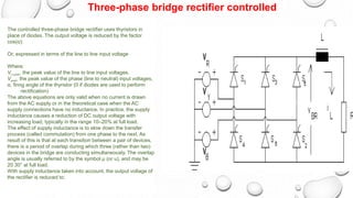
- 17. The controlled three-phase bridge rectifier uses thyristors in place of diodes. The output voltage is reduced by the factor cos(Îą): Or, expressed in terms of the line to line input voltage Where: VLLpeak, the peak value of the line to line input voltages, Vpeak, the peak value of the phase (line to neutral) input voltages, Îą, firing angle of the thyristor (0 if diodes are used to perform rectification) The above equations are only valid when no current is drawn from the AC supply or in the theoretical case when the AC supply connections have no inductance. In practice, the supply inductance causes a reduction of DC output voltage with increasing load, typically in the range 10â20% at full load. The effect of supply inductance is to slow down the transfer process (called commutation) from one phase to the next. As result of this is that at each transition between a pair of devices, there is a period of overlap during which three (rather than two) devices in the bridge are conducting simultaneously. The overlap angle is usually referred to by the symbol Ξ (or u), and may be 20 30° at full load. With supply inductance taken into account, the output voltage of the rectifier is reduced to: Three-phase bridge rectifier controlled
- 18. Twelve-pulse bridge Although better than single-phase rectifiers or three-phase half-wave rectifiers, six- pulse rectifier circuits still produce considerable harmonic distortion on both the AC and DC connections. For very high- power rectifiers the twelve-pulse bridge connection is usually used. A twelve-pulse bridge consists of two six-pulse bridge circuits connected in series, with their AC connections fed from a supply transformer that produces a 30° phase shift between the two bridges. This cancels many of the characteristic harmonics the six-pulse bridges produce. The 30 degree phase shift is usually achieved by using a transformer with two sets of secondary windings, one in star (wye) connection and one in delta connecti
- 19. Ferdinand Braun






![Full-wave rectification
A full-wave bridge rectifier converts the
whole of the input waveform to one of
constant polarity (positive or negative)
at its output. Mathematically, this
corresponds to the absolute
value function. Full-wave rectification
converts both polarities of the input
waveform to pulsating DC (direct
current), and yields a higher average
output voltage. Two diodes and
a center tapped transformer, or four
diodes in a bridge configuration and
any AC source (including a transformer
without center tap), are
needed.[3]Single semiconductor
diodes, double diodes with common
cathode or common anode, and four-
diode bridges, are manufactured as
single components](https://image.slidesharecdn.com/rectifiers-180123134051/85/Rectifiers-10-320.jpg)


