Reducing error when reverse engineering mechanical parts
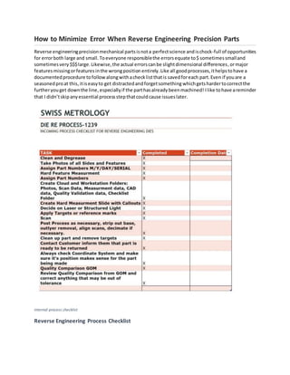
- 1. How to Minimize Error When Reverse Engineering Precision Parts Reverse engineeringprecisionmechanical partsisnota perfectscience andischock-full of opportunities for errorboth large and small.Toeveryone responsiblethe errorsequate to$ sometimessmalland sometimesvery $$$large.Likewise,the actual errorscanbe slightdimensional differences, ormajor featuresmissingorfeatures inthe wrongposition entirely.Like all goodprocesses,ithelpstohave a documentedprocedure tofollowalongwithachecklistthatis savedforeach part.Even if youare a seasonedproat this,itiseasyto get distractedandforgetsomething whichgetshardertocorrectthe furtheryouget downthe line,especiallyif the parthasalreadybeenmachined! Ilike tohave areminder that I didn’tskipanyessential processstepthatcouldcause issueslater. internal process checklist Reverse Engineering Process Checklist
- 2. Clean, degrease, remove metal fragment and other foreign substances. From myperspective we are alwaysthinkingthatwe are goingto be scanningthe parts so a perfectly cleanpart isessential, butwhenusinganytype of “hardmeasurement”tools youare goingto compromise accuracyby measuringdirtysurfacesoftenmeasuringthe dirtandnotthe surface,notto mentiongettingthe grease andgunkonyourmeasuringtools,whichwill cause youproblemsinfuture project,unlesscleanedupafter.
- 4. Pictures I like totake picturesof the part from everyangle andcapture everysurface asthe sayinggoes“a picture iswortha thousandwords.”Thisprovidesarecordof the original partwhichcan be valuable duringmodelingandequallyvaluable if anyquestionsarise downthe line afteryouare complete.
- 5. Checking overall part length via height Hard Measurements Although3D scanningwithqualityequipmentandexperiencedandknowledgeable personnel canbe bothaccurate and precise itisalwaysa goodpractice to capture any harddata that is easilyavailable.I especiallytrytocapture overall dimensionsincase stockhastobe orderedforthe replacementpartsas well ashole diameters. Thisisespeciallyimportantforsmall holes.Iusuallyuse aplugandpingages and evenleave theminduringscanning,sinceitiseasiertopickout a cylinderratherthana hole while you are modelingthe part. Youalsoneedtocapture featuressuchasthreadedholessize andpitchaswell as depthsandcounterbore/countersinksdimension. Again,thisprovidesagoodreference whileyouare modelingthe partas well as,aquickconfirmationthatsome sortof inadvertentscalinghappened betweenconversionsaswell as,aquickcheck if issues regardingaccuracycome up afteryouare done.
- 6. Laser scanned mesh model of part Scan data Of course, nothingcanbeataccurate scan data. Whenyoubringthisintoyour reverse engineering applicationyouhave atremendousamountof 3D data inyour workspace todevelopacomplete CAD model of yourpart.
- 7. CAD model of part created from scan
- 8. Checking surface curvature continuity Modeling While modeling,reference hardreference dataespeciallywithfeaturesthatare hard to resolve from the scan data. Checksurface curvature continuity. Alsokeepinmindthe designintent.Isthe partto be simplyareproductionof whatisavailable orare there improvementsandorchangesto be made. Sometimesthe partmayhave a set of surfacesmissingthatwere damagedinmanufacturing.These oftenhave tobe carefullyreproducedbasedonthe “bestavailable”information.Finally,make Ilike to make sure that the part is alignedinthe X,Y,Z coordinate systeminaway thatmakessense forthe customerand the application.
- 9. Scan to CAD comparison Compare CAD to original scan As a final check,we runa CADto part analysistosee if anythingismissingora surface isout of the anticipatedtolerance zone. William DPlutnick WilliamD.Plutnick President/CEO | Swiss Metrology
- 10. 16 South Queen St. Mt. Sterling, KY 40353 Ph: (859) 432-8179 | C: (606) 782-4011 www.swissmetrology.com https://www.facebook.com/swissmetrology/ https://twitter.com/Metrologyman_1


