


More Related Content
Similar to Repairing and Strengthening of Concrete structures (18)
Repairing and Strengthening of Concrete structures
- 1. REPAIR AND STRENGTHENING OF CONCRETE STRUCTURES CES423 : Construction Engineering (2) Submitted by: Abdallah Shahen Mohamed ID:15P1003 Ahmed Bahaa El Din Aly ID:15P1012 Ahmed Essam Ali ID:15P1051 Islam Mohamed El Sayed ID:15P1023 Mohamed Karam Sayed ID:15P5002 Nael Hesham Ahmed ID:15P6015 Seif Ahmed Mohamed ID:15P1022 Youssed Ehab Salah ID:15P1041 Submitted to: Dr. Amgad Talaat Ain Shams University Faculty of Engineering Credit Hours Engineering Program NOVEMBER 5, 2019
- 2. 1| P a g e Table of Contents Case Study (1).......................................................................................................................... 2 1.1.Introduction:.................................................................................................................. 2 1.2.Description of structure:............................................................................................... 2 1.3.Preview on Nature:........................................................................................................ 2 1.4.Conclusion and Recommendations:............................................................................. 4 1.5.Introduction:.................................................................................................................. 6 1.6.Description of structure:............................................................................................... 6 1.7.Preview on Nature:........................................................................................................ 6 1.8.Conclusion and Recommendations:............................................................................. 6 1.9.General Conclusion:...................................................................................................... 6 1.10. General Recommendations: ...................................................................................... 7 Case Study (2).......................................................................................................................... 9 2.1.Introduction:.................................................................................................................. 9 2.2.Virtual Previews:......................................................................................................... 10 2.3.Survey Results: ............................................................................................................ 11 2.4.Conclusion and Recommendations:........................................................................... 13 2.4.1. Conclusion:........................................................................................................... 13 2.4.2. Recommendations: .............................................................................................. 13 Case Study (3)........................................................................................................................ 15 3.1.Introduction:................................................................................................................ 15 3.2.Distress Observed:....................................................................................................... 15 3.3.Repair of Cracks in Masonary walls: ........................................................................ 16 3.4.Repair and Strengthening of RCC Columns ,Beams and Slabs: ............................ 17 3.5.Strengthen of Masonary Columns:............................................................................ 18 3.6. External Wall Plastering and Protective Coating: .................................................. 18
- 3. 2| P a g e )1(Case Study ŌĆ½ž╣┘ģž¦ž▒ž®ŌĆ¼B3ŌĆōŌĆ½┘ģž¼┘ģ┘łž╣ž®ŌĆ¼33ŌĆōŌĆ½┘ģŌĆ¼ŌĆ½ž»┘Ŗ┘垬┘ŖŌĆ¼ ŌĆ½┘ģž┤ž▒┘łž╣ŌĆ¼ ŌĆ½ž¬┘éž▒┘Ŗž▒ž¦┘䞬ž▒ž©ž®ŌĆ¼ ŌĆ½ž©ž╣ž»ŌĆ¼ ŌĆ½┘ä┘äž╣┘ģž¦ž▒ž®ŌĆ¼ ŌĆ½ž¦žŻ┘ä┘ł┘ä┘ēŌĆ¼ ŌĆ½ž¦┘ä┘ģž¬ž¦ž©ž╣ž®ŌĆ¼ŌĆ½┘ģž»┘Ŗ┘垬┘ēŌĆ¼ :Introduction.1.1 ŌĆ½┘łž¦┘䞬žĘ┘ł┘Ŗž▒ŌĆ¼ ŌĆ½┘ä┘ä┘ģž┤ž▒┘łž╣ž¦ž¬ŌĆ¼ ŌĆ½ž¦┘äž╣ž▒ž©┘Ŗž®ŌĆ¼ ŌĆ½ž¦┘äž┤ž▒┘āž®ŌĆ¼ ŌĆ½ž¬┘ā┘ä┘Ŗ┘üŌĆ¼ ŌĆ½ž╣┘ä┘ēŌĆ¼ ŌĆ½ž©┘垦žĪŌĆ¼ ŌĆ½ž¦┘䞬┘éž▒┘Ŗž▒ŌĆ¼ ŌĆ½┘ćž░ž¦ŌĆ¼ ŌĆ½žźž╣ž»ž¦ž»ŌĆ¼ ŌĆ½ž¬┘ģŌĆ¼ŌĆ½ž¦ŌĆ¼ŌĆ½┘äž╣┘ģž▒ž¦ŌĆ¼ŌĆ½┘å┘ēŌĆ¼ ŌĆ½ž¦┘ä┘ģ┘łž¼ŌĆ¼ ŌĆ½ž¦┘äžĖž¦┘ćž▒┘Ŗž®ŌĆ¼ ŌĆ½ž¦┘äž╣┘Ŗ┘łž©ŌĆ¼ ŌĆ½┘ģž╣ŌĆ¼ ŌĆ½ž¦┘䞬ž╣ž¦┘ģ┘äŌĆ¼ ŌĆ½ž¦ž│┘ä┘łž©ŌĆ¼ ŌĆ½ž╣┘åŌĆ¼ ŌĆ½ž¬┘éž▒┘Ŗž▒ŌĆ¼ ŌĆ½┘łž¦ž╣ž»ž¦ž»ŌĆ¼ ŌĆ½ž¦┘äž╣┘ģž¦ž▒ž®ŌĆ¼ ŌĆ½ž©┘ģž╣ž¦┘Ŗ┘åž®ŌĆ¼ŌĆ½ž©ŌĆ¼ ŌĆ½┘łž»ž®ŌĆ¼ŌĆ½┘枦ŌĆ¼. :Description of structure.1.2 ŌĆ½┘ģ┘åŌĆ¼ ŌĆ½┘ģ┘ā┘ł┘åž®ŌĆ¼ ŌĆ½ž¦┘ä┘ģž╣ž¦┘Ŗ┘åž®ŌĆ¼ ŌĆ½┘ģ┘łžČ┘łž╣ŌĆ¼ ŌĆ½ž¦┘äž╣┘ģž¦ž▒ž®ŌĆ¼ŌĆ½┘łŌĆ¼ ŌĆ½žŻž▒žČ┘ēŌĆ¼ ŌĆ½žĘž¦ž©┘éŌĆ¼┘”ŌĆ½ž©ž¦ž│ž¬ŌĆ¼ ŌĆ½ž¦žź┘ä┘åž┤ž¦žĪŌĆ¼ ŌĆ½ž¬┘ģŌĆ¼ ŌĆ½┘ł┘éž»ŌĆ¼ ŌĆ½žĘ┘łž¦ž©┘éŌĆ¼ŌĆ½ž«ž»ž¦┘ģŌĆ¼ ŌĆ½ž¦┘ä┘ģž│┘䞣ž®ŌĆ¼ ŌĆ½ž¦┘äž«ž▒ž│ž¦┘åž®ŌĆ¼ ŌĆ½┘ģ┘åŌĆ¼ ŌĆ½ž¦┘ä┘ć┘Ŗ┘ā┘ä┘ēŌĆ¼ ŌĆ½ž¦┘ä┘åžĖž¦┘ģŌĆ¼. :Preview on Nature.1.3 ŌĆ½ž©ž¬ž¦ž▒┘Ŗž«ŌĆ¼ ŌĆ½ž¦┘äž╣┘ģž¦ž▒ž®ŌĆ¼ ŌĆ½┘ģž╣ž¦┘Ŗ┘åž®ŌĆ¼ ŌĆ½ž¬┘ģž¬ŌĆ¼┘ó┘¦ŌĆ½ž»┘Ŗž│┘ģž©ž▒ŌĆ¼┘ó┘Ā┘Ī┘żŌĆ½ž¦┘äžĖž¦┘ćž▒┘Ŗž®ŌĆ¼ ŌĆ½ž¦┘ä┘ģž╣ž¦┘Ŗ┘åž®ŌĆ¼ ŌĆ½┘ģ┘åŌĆ¼ ŌĆ½ž¦ž¬žČžŁŌĆ¼ ŌĆ½┘ł┘éž»ŌĆ¼:ŌĆ½┘Ŗ┘ä┘ēŌĆ¼ ŌĆ½┘ģž¦ŌĆ¼ -ŌĆ½ž¦┘ä┘ģž¼ž¦┘łž▒ž®ŌĆ¼ ŌĆ½ž¦┘äž╣┘ģž¦ž▒ž¦ž¬ŌĆ¼ ŌĆ½žŁž»ž¦ž”┘éŌĆ¼ ┘ŗŌĆ½ž¦ŌĆ¼ŌĆ½┘łž¦┘ŖžČŌĆ¼ ŌĆ½ž¦┘äž╣┘ģž¦ž▒ž®ŌĆ¼ ŌĆ½žŁž»┘Ŗ┘éž®ŌĆ¼ ŌĆ½ž▓ž▒ž¦ž╣ž®ŌĆ¼ ŌĆ½ž¬┘ģŌĆ¼. -ŌĆ½ž¦┘ü┘é┘Ŗž®ŌĆ¼ ŌĆ½ž┤ž▒┘łž«ŌĆ¼ ŌĆ½┘łž¼┘łž»ŌĆ¼ ŌĆ½ž¬ž¦┘䞣žĖŌĆ¼ŌĆ½┘ä┘äž╣┘ģž¦ž▒ž®ŌĆ¼ ŌĆ½ž¦┘äž«ž¦ž▒ž¼┘Ŗž®ŌĆ¼ ŌĆ½ž¦┘䞣┘łž¦ž”žĘŌĆ¼ ŌĆ½ž©ž©ž╣žČŌĆ¼ ŌĆ½┘ł┘ģž¦ž”┘äž®ŌĆ¼. ŌĆ½žŻž▒┘鞦┘ģŌĆ¼ ŌĆ½ž¦┘ä┘łžŁž»ž¦ž¬ŌĆ¼ ŌĆ½┘ģž╣ž¦┘Ŗ┘åž®ŌĆ¼ ŌĆ½ž¬┘ģž¬ŌĆ¼: ŌĆ½ž¦┘䞬ž¦┘ä┘ēŌĆ¼ ŌĆ½┘ł┘łž¼ž»ŌĆ¼ ŌĆ½ž©ž¦┘äž╣┘ģž¦ž▒ž®ŌĆ¼ -ŌĆ½ž¦žó┘ä┘åŌĆ¼ ŌĆ½žź┘ä┘ēŌĆ¼ ŌĆ½ž¬ž│┘ā┘åŌĆ¼ ŌĆ½┘ł┘ä┘ģŌĆ¼ ŌĆ½┘ģ┘å┘枦ŌĆ¼ ŌĆ½ž¦ž¦┘ä┘垬┘枦žĪŌĆ¼ ŌĆ½ž¬┘ģŌĆ¼ ŌĆ½ž¦┘ä┘łžŁž»ž¦ž¬ŌĆ¼. -ŌĆ½ž¦┘äž│┘é┘üŌĆ¼ ŌĆ½┘łŌĆ¼ ŌĆ½ž¦┘䞣┘łž¦ž”žĘŌĆ¼ ŌĆ½ž©┘Ŗ┘åŌĆ¼ ŌĆ½ž¦┘ü┘é┘Ŗž®ŌĆ¼ ŌĆ½ž┤ž▒┘łž«ŌĆ¼ ŌĆ½┘łž¼┘łž»ŌĆ¼ ŌĆ½ž¬ž¦┘䞣žĖŌĆ¼. -ŌĆ½┘ģžĄ┘åž╣┘ŖŌĆ¼ ŌĆ½ž│┘łžĪŌĆ¼ ŌĆ½ž©ž│ž©ž©ŌĆ¼ ŌĆ½┘łž░┘ä┘āŌĆ¼ ŌĆ½ž¦┘äž▒┘Ŗž│ž©ž┤┘åŌĆ¼ ŌĆ½ž©žŁž¦ž”žĘŌĆ¼ ŌĆ½ž¦┘äž╣┘ģ┘łž»ŌĆ¼ ŌĆ½ž¼ž¦┘åž©┘ēŌĆ¼ ŌĆ½ž╣┘ä┘ēŌĆ¼ ŌĆ½ž┤ž▒┘łž«ŌĆ¼ ŌĆ½┘łž¼┘łž»ŌĆ¼ ŌĆ½ž¬ž¦┘䞣žĖŌĆ¼ŌĆ½ž®ŌĆ¼ ŌĆ½ž¬┘āž▒ž¦ž▒┘ćŌĆ¼ ŌĆ½┘ģž╣ŌĆ¼ŌĆ½ž¦┘äž╣┘ģž¦ž▒ž®ŌĆ¼ ŌĆ½┘ü┘ēŌĆ¼ ŌĆ½ž¦┘ä┘ģž┤ž¦ž©┘ćž®ŌĆ¼ ŌĆ½ž¦┘ä┘å┘ģž¦ž░ž¼ŌĆ¼ ŌĆ½ž¼┘ģ┘Ŗž╣ŌĆ¼ ŌĆ½┘ü┘ēŌĆ¼ -ŌĆ½žŻ┘üŌĆ¼ ŌĆ½žŻ┘łŌĆ¼ ŌĆ½┘ģž¦ž”┘äž®ŌĆ¼ ŌĆ½┘łž¦┘äž┤ž©ž¦ž©┘Ŗ┘āŌĆ¼ ŌĆ½ž¦žŻ┘äž©┘łž¦ž©ŌĆ¼ ŌĆ½┘üž¬žŁž¦ž¬ŌĆ¼ ŌĆ½ž©ž¼┘łž¦ž▒ŌĆ¼ ŌĆ½ž┤ž▒┘łž«ŌĆ¼ ŌĆ½ž╣ž»ž®ŌĆ¼ ŌĆ½┘łž¼┘łž»ŌĆ¼ ┘ŗŌĆ½ž¦ŌĆ¼ŌĆ½žŻ┘ŖžČŌĆ¼ ŌĆ½ž¬ž¦┘䞣žĖŌĆ¼ŌĆ½žŻŌĆ¼ ŌĆ½┘é┘Ŗž®ŌĆ¼ŌĆ½┘łŌĆ¼ ŌĆ½ž▒žŻž│┘Ŗž®ŌĆ¼ -ŌĆ½ž¦┘ä┘ģž¼ž¦┘łž▒ž®ŌĆ¼ ŌĆ½ž¦┘䞣ž¼ž▒ž¦ž¬ŌĆ¼ ŌĆ½žź┘ä┘ēŌĆ¼ ŌĆ½┘垦┘üž░ž®ŌĆ¼ ŌĆ½ž┤ž▒┘łž«ŌĆ¼ ŌĆ½ž©┘ćŌĆ¼ ŌĆ½ž¦┘äž│┘é┘üŌĆ¼ ŌĆ½┘ģž╣ŌĆ¼ ŌĆ½ž¦┘䞣┘łž¦ž”žĘŌĆ¼ ŌĆ½ž¦ž¬žĄž¦┘äŌĆ¼ -ŌĆ½ž¦┘ä┘ā┘ćž▒ž©ž¦žĪŌĆ¼ ŌĆ½┘ģž«ž¦ž▒ž¼ŌĆ¼ ŌĆ½┘ģ┘åŌĆ¼ ŌĆ½ž©ž»ž¦┘Ŗž¬┘枦ŌĆ¼ ŌĆ½ž┤ž▒┘łž«ŌĆ¼ ŌĆ½┘łž¼┘łž»ŌĆ¼ ŌĆ½ž¬ž¦┘䞣žĖŌĆ¼. -ŌĆ½ž¦┘äž▒┘Ŗž│ž©ž┤┘åŌĆ¼ ŌĆ½ž¦ž¬žĄž¦┘äŌĆ¼ ŌĆ½ž©┘Ŗ┘åŌĆ¼ ŌĆ½ž┤ž▒┘łž«ŌĆ¼ ŌĆ½┘łž¼┘łž»ŌĆ¼ ŌĆ½ž¬ž¦┘䞣žĖŌĆ¼ŌĆ½ž¦žó┘äŌĆ¼ ŌĆ½ž¦┘äž¼┘枦ž¬ŌĆ¼ ŌĆ½┘ü┘ēŌĆ¼ ŌĆ½┘ł┘垦┘üž░ŌĆ¼ ŌĆ½ž¦┘䞬┘łž▓┘Ŗž╣ŌĆ¼ ŌĆ½ž©žĘž▒┘éž®ŌĆ¼ŌĆ½ž«ž▒┘ēŌĆ¼ ŌĆ½ž¦┘äž╣┘ģž¦ž▒ž®ŌĆ¼ ŌĆ½┘ü┘ēŌĆ¼ ŌĆ½ž¦┘ä┘ģž┤ž¦ž©┘ćž®ŌĆ¼ ŌĆ½ž¦┘ä┘å┘ģž¦ž░ž¼ŌĆ¼ ŌĆ½ž¼┘ģ┘Ŗž╣ŌĆ¼ ŌĆ½┘ü┘ēŌĆ¼ ŌĆ½┘ģ┘āž▒ž▒ŌĆ¼ ŌĆ½ž¦┘äž┤ž▒ž«ŌĆ¼ ŌĆ½┘ł┘ćž░ž¦ŌĆ¼
- 4. 3| P a g e -ŌĆ½┘ģžĄ┘åž╣┘Ŗž®ŌĆ¼ ŌĆ½ž│┘łžĪŌĆ¼ ŌĆ½┘ģ┘åŌĆ¼ ŌĆ½ž╣ž¦ž»┘ćŌĆ¼ ŌĆ½ž¬┘垬ž¼ŌĆ¼ ŌĆ½┘ł┘ć┘ēŌĆ¼ ŌĆ½ž┤ž╣ž▒┘Ŗž®ŌĆ¼ ŌĆ½ž┤ž▒┘łž«ŌĆ¼ ŌĆ½┘ģž¦┘䞣žĖž¬┘枦ŌĆ¼ ŌĆ½ž¬┘ģŌĆ¼ ŌĆ½ž¦┘䞬┘ēŌĆ¼ ŌĆ½ž¦┘äž┤ž▒┘łž«ŌĆ¼ ŌĆ½┘ģž╣žĖ┘ģŌĆ¼ŌĆ½┘ü┘ēŌĆ¼ ŌĆ½┘łž¦┘ä┘ģŌĆ¼ ŌĆ½ž¦┘äž«ž▒ž│ž¦┘å┘ēŌĆ¼ ŌĆ½ž¦┘ä┘ć┘Ŗ┘ā┘äŌĆ¼ ŌĆ½ž©┘Ŗ┘åŌĆ¼ ŌĆ½┘łž¦┘äž▒žŻž│┘Ŗž®ŌĆ¼ ŌĆ½ž¦žŻ┘ä┘ü┘é┘Ŗž®ŌĆ¼ ŌĆ½ž¦┘äž┤ž▒┘łž«ŌĆ¼ ŌĆ½(ž«ž¦žĄž®ŌĆ¼ ŌĆ½ž¦┘䞬┘å┘ü┘Ŗž░ŌĆ¼ ŌĆ½žŻž╣┘ģž¦┘äŌĆ¼ŌĆ½ž©ž¦┘å┘ēŌĆ¼ )ŌĆ½ž¦┘ä┘üž¬žŁž¦ž¬ŌĆ¼ ŌĆ½žŁ┘ł┘äŌĆ¼ ŌĆ½┘łž¦┘äž┤ž▒┘łž«ŌĆ¼ŌĆ½┘åž│ž©┘ŖŌĆ¼ ŌĆ½žŁž▒┘āž®ŌĆ¼ ŌĆ½žŁž»┘łž½ŌĆ¼ ŌĆ½┘垬┘Ŗž¼ž®ŌĆ¼ ŌĆ½ž¬žŻž½ž▒┘枦ŌĆ¼ ŌĆ½ž¦žŁž¬┘ģž¦┘äŌĆ¼ ŌĆ½žź┘ä┘ēŌĆ¼ ŌĆ½ž©ž¦žŻ┘äžČž¦┘üž®ŌĆ¼ŌĆ½ž®ŌĆ¼ ŌĆ½ž©ž│┘ŖžĘž®ŌĆ¼.
- 5. 4| P a g e :Conclusion and Recommendations.1.4 ’éĘŌĆ½ž¦┘äž┤ž▒┘łŌĆ¼ ŌĆ½ž╣┘ä┘ŖŌĆ¼ ŌĆ½ž¬žŻž½┘Ŗž▒ŌĆ¼ ŌĆ½ž¦┘ŖŌĆ¼ ŌĆ½┘ä┘枦ŌĆ¼ ŌĆ½┘ä┘Ŗž│ŌĆ¼ ŌĆ½┘łŌĆ¼ ŌĆ½┘ģž¬ž▓┘åž®ŌĆ¼ ŌĆ½žĘž©┘Ŗž╣ž®ŌĆ¼ ŌĆ½ž¦┘äž╣┘ģž¦ž▒ž®ŌĆ¼ ŌĆ½ž¦ž│┘ü┘äŌĆ¼ ŌĆ½ž¦┘䞬ž▒ž©ž®ŌĆ¼ ŌĆ½žĘž©┘Ŗž╣ž®ŌĆ¼ŌĆ½ž©ž¦┘äŌĆ¼ ŌĆ½ž«ŌĆ¼ŌĆ½ž╣┘ģž¦ž▒ž®ŌĆ¼ ’éĘŌĆ½ž¦┘äžĘž▒┘éŌĆ¼ ŌĆ½┘łŌĆ¼ ŌĆ½ž©ž¦┘ä┘łžŁž»ž®ŌĆ¼ ŌĆ½ž¦┘ä┘ģ┘łž¼┘łž»ž®ŌĆ¼ ŌĆ½ž©ž¦┘äž┤ž▒┘łž«ŌĆ¼ ŌĆ½ž¬┘üžĄ┘Ŗ┘ä┘ŖŌĆ¼ ŌĆ½ž│ž¼┘äŌĆ¼ ŌĆ½ž╣┘ģ┘äŌĆ¼ ŌĆ½┘Ŗž¬┘ģŌĆ¼ŌĆ½┘ü┘ŖŌĆ¼ ŌĆ½ž¦┘ä┘ģž│ž¬ž«ž»┘ģž®ŌĆ¼ ŌĆ½┘ģž│ž¬┘éž©ž¦┘äŌĆ¼ ŌĆ½ž¦┘ä┘Ŗ┘枦ŌĆ¼ ŌĆ½┘ä┘äž▒ž¼┘łž╣ŌĆ¼ ŌĆ½ž¦┘䞬┘å┘ü┘Ŗž░ŌĆ¼ ŌĆ½žŻž½┘垦žĪŌĆ¼ ŌĆ½žĄ┘łž▒ŌĆ¼ ŌĆ½┘łŌĆ¼ ŌĆ½ž¦┘äž╣ž¦┘äž¼ŌĆ¼ ŌĆ½ž¬ž¦ž▒┘Ŗž«ŌĆ¼ ŌĆ½┘łŌĆ¼ ŌĆ½ž╣ž¦┘äž¼┘枦ŌĆ¼ ’éĘŌĆ½┘ä┘äž╣┘ģž¦ž▒ž®ŌĆ¼ ŌĆ½ž¦ž¦┘ä┘åž┤ž¦ž”┘Ŗž®ŌĆ¼ ŌĆ½ž©ž¦┘ä┘ä┘łžŁž¦ž¬ŌĆ¼ ŌĆ½ž¦┘ä┘äž¼┘åž®ŌĆ¼ ŌĆ½┘ģ┘łž¦┘üž¦ž®ŌĆ¼ ŌĆ½┘Ŗž¬┘ģŌĆ¼ ’éĘŌĆ½ž¦┘äŌĆ¼ ŌĆ½žŁ┘Ŗž½ŌĆ¼ ŌĆ½ž¦┘äž»ž▒ž¦ž│ž®ŌĆ¼ ŌĆ½┘üž¬ž▒ž®ŌĆ¼ ŌĆ½žŻž½┘垦žĪŌĆ¼ ŌĆ½ž¦┘äž│┘ā┘åŌĆ¼ ŌĆ½ž║ž▒žČŌĆ¼ ŌĆ½┘ü┘ŖŌĆ¼ ŌĆ½ž¦┘ä┘łžŁž»ž®ŌĆ¼ ŌĆ½ž¦ž│ž¬ž«ž»ž¦┘ģŌĆ¼ ŌĆ½┘ģ┘åŌĆ¼ ŌĆ½┘Ŗ┘ģ┘åž╣ŌĆ¼ ŌĆ½┘ģž¦ŌĆ¼ ŌĆ½┘Ŗ┘łž¼ž»ŌĆ¼ ŌĆ½ž¦┘äŌĆ¼ ŌĆ½ž╣┘ä┘Ŗ┘枦ŌĆ¼ ŌĆ½ž¦┘åž┤ž¦ž”┘Ŗž®ŌĆ¼ ŌĆ½ž«žĘ┘łž▒ž®ŌĆ¼ ŌĆ½┘łž¼┘łž»ŌĆ¼ ŌĆ½ž¦┘ä┘ŖŌĆ¼ ŌĆ½ž¬ž┤┘Ŗž▒ŌĆ¼ ŌĆ½ž╣ž¦┘ä┘ģž¦ž¬ŌĆ¼ ŌĆ½ž¦┘ŖŌĆ¼ ŌĆ½ž¬┘łž¼ž»ŌĆ¼
- 6. 5| P a g e
- 7. 6| P a g e ŌĆ½ž¦┘äž╣┘ģž¦ž▒ž¬┘Ŗ┘åŌĆ¼ ŌĆ½ž©┘Ŗ┘åŌĆ¼ ŌĆ½ž¦ž¦┘ä┘åž┤ž¦ž”┘ŖŌĆ¼ ŌĆ½┘ä┘ä┘üž¦žĄ┘äŌĆ¼ ŌĆ½┘ģž©ž»ž”┘Ŗž®ŌĆ¼ ŌĆ½┘ģž╣ž¦┘Ŗ┘åž®ŌĆ¼ŌĆ½┘ģž┤ž▒┘łž╣ŌĆ¼ŌĆ½┘ģž»┘Ŗ┘垬┘ŖŌĆ¼ :Introduction.51. ŌĆ½ž¦ŌĆ¼ ŌĆ½┘ä┘䞬žĘ┘ł┘Ŗž▒ŌĆ¼ ŌĆ½┘ä┘ä┘ģž┤ž▒┘łž╣ž¦ž¬ŌĆ¼ ŌĆ½ž¦┘äž╣ž▒ž©┘Ŗž®ŌĆ¼ ŌĆ½ž¦┘äž┤ž▒┘āž®ŌĆ¼ ŌĆ½ž¬┘ā┘ä┘Ŗ┘üŌĆ¼ ŌĆ½ž╣┘ä┘ŖŌĆ¼ ŌĆ½ž©┘垦žĪŌĆ¼ ŌĆ½ž¦┘䞬┘éž▒┘Ŗž▒ŌĆ¼ ŌĆ½┘ćž░ž¦ŌĆ¼ ŌĆ½ž¦ž╣ž»ž¦ž»ŌĆ¼ ŌĆ½ž¬┘ģŌĆ¼ŌĆ½┘äž╣┘ģž▒ž¦ŌĆ¼ŌĆ½┘å┘ŖŌĆ¼ ŌĆ½ž¦┘äŌĆ¼ ŌĆ½┘ģž╣ŌĆ¼ ŌĆ½ž¦┘䞬ž╣ž¦┘ģ┘äŌĆ¼ ŌĆ½ž¦ž│┘ä┘łž©ŌĆ¼ ŌĆ½ž╣┘åŌĆ¼ ŌĆ½ž¬┘éž▒┘Ŗž▒ŌĆ¼ ŌĆ½ž¦ž╣ž»ž¦ž»ŌĆ¼ ŌĆ½┘łŌĆ¼ ŌĆ½ž¦┘äž╣┘ģž¦ž▒ž¬┘Ŗ┘åŌĆ¼ ŌĆ½ž©┘Ŗ┘åŌĆ¼ ŌĆ½ž¦┘䞬┘ģž»ž»ŌĆ¼ ŌĆ½┘üž¦žĄ┘äŌĆ¼ ŌĆ½ž©┘ģž╣ž¦┘Ŗ┘åž®ŌĆ¼ŌĆ½ž╣┘Ŗ┘łž©ŌĆ¼ ŌĆ½ž¦┘ä┘ģ┘łž¼┘łž»ž®ŌĆ¼ ŌĆ½ž¦┘äžĖž¦┘ćž▒┘Ŗž®ŌĆ¼ŌĆ½ž©┘枦ŌĆ¼. :Description of structure.61. ŌĆ½┘łŌĆ¼ ŌĆ½ž¦ž▒žČ┘ŖŌĆ¼ ŌĆ½žĘž¦ž©┘éŌĆ¼ ŌĆ½┘ģ┘åŌĆ¼ ŌĆ½┘ģ┘ā┘ł┘åž®ŌĆ¼ ŌĆ½ž¦┘ä┘ģž╣ž¦┘Ŗ┘åž®ŌĆ¼ ŌĆ½┘ģ┘łžČ┘łž╣ŌĆ¼ ŌĆ½ž¦┘äž╣┘ģž¦ž▒ž®ŌĆ¼┘”ŌĆ½ž©ž¦ŌĆ¼ ŌĆ½ž¦ž¦┘ä┘åž┤ž¦žĪŌĆ¼ ŌĆ½ž¬┘ģŌĆ¼ ŌĆ½┘éž»ŌĆ¼ ŌĆ½┘łŌĆ¼ ŌĆ½žĘ┘łž¦ž©┘éŌĆ¼ŌĆ½ž│ž¬ž«ž»ž¦┘ģŌĆ¼ ŌĆ½ž¦┘ä┘ģž│┘䞣ž®ŌĆ¼ ŌĆ½ž¦┘äž«ž▒ž│ž¦┘åž®ŌĆ¼ ŌĆ½┘ģ┘åŌĆ¼ ŌĆ½ž¦┘ä┘ć┘Ŗ┘ā┘ä┘ŖŌĆ¼ ŌĆ½ž¦┘ä┘åžĖž¦┘ģŌĆ¼ :Preview on Nature.71. ŌĆ½ž©ž¬ž¦ž▒┘Ŗž«ŌĆ¼ ŌĆ½ž¦┘ä┘üž¦žĄ┘äŌĆ¼ ŌĆ½┘ģž╣ž¦┘Ŗ┘åž®ŌĆ¼ ŌĆ½ž¬┘ģž¬ŌĆ¼┘ó┘źŌĆ½┘üž©ž▒ž¦┘Ŗž▒ŌĆ¼┘ó┘Ā┘Ī┘¦ŌĆ½ž¦┘äžĖž¦┘ćž▒┘ŖŌĆ¼ ŌĆ½ž¦┘ä┘ģž╣ž¦┘Ŗ┘åž®ŌĆ¼ ŌĆ½┘ģ┘åŌĆ¼ ŌĆ½ž¦ž¬žČžŁŌĆ¼ ŌĆ½┘ł┘éž»ŌĆ¼:ŌĆ½┘Ŗ┘ä┘ŖŌĆ¼ ŌĆ½┘ģž¦ŌĆ¼ ŌĆ½ž®ŌĆ¼ -ŌĆ½ž¬ŌĆ¼ŌĆ½žŁ┘ł┘ä┘ćŌĆ¼ ŌĆ½ž¦┘䞣ž»ž¦ž”┘éŌĆ¼ ŌĆ½ž▓ž▒ž¦ž╣ž®ŌĆ¼ ŌĆ½┘łŌĆ¼ ŌĆ½ž©ž¦┘äž│┘āž¦┘åŌĆ¼ ŌĆ½ž┤ž║┘ä┘ć┘ģž¦ŌĆ¼ ŌĆ½┘łŌĆ¼ ŌĆ½ž¦┘äž╣┘ģž¦ž▒ž¬┘Ŗ┘åŌĆ¼ ŌĆ½ž¬ž┤žĘ┘Ŗž©ŌĆ¼ ŌĆ½┘ģ┘åŌĆ¼ ŌĆ½ž¦ž¦┘ä┘垬┘枦žĪŌĆ¼ ŌĆ½┘ģŌĆ¼ŌĆ½┘ģž¦ŌĆ¼ -ŌĆ½ž¦┘äž╣┘ģž¦ž▒ž¬┘Ŗ┘åŌĆ¼ ŌĆ½ž©┘Ŗ┘åŌĆ¼ ŌĆ½ž¦┘䞬┘ģž»ž»ŌĆ¼ ŌĆ½ž©┘üž¦žĄ┘äŌĆ¼ ŌĆ½žŁž▒┘āž®ŌĆ¼ ŌĆ½┘łž¼┘łž»ŌĆ¼ ŌĆ½┘垦┘䞣žĖŌĆ¼ :Conclusion and Recommendations.81. ’éĘŌĆ½┘ä┘ģŌĆ¼ ŌĆ½┘łŌĆ¼ ŌĆ½ž¦┘䞬┘ģž»ž»ŌĆ¼ ŌĆ½┘üž¦žĄ┘äŌĆ¼ ŌĆ½┘ü┘ŖŌĆ¼ ŌĆ½žĖ┘ćž▒ž¬ŌĆ¼ ŌĆ½ž¦┘䞬┘ŖŌĆ¼ ŌĆ½ž¦┘äž╣┘Ŗ┘łž©ŌĆ¼ ŌĆ½ž¦┘åŌĆ¼ ŌĆ½┘Ŗž¬žČžŁŌĆ¼ ŌĆ½ž¦┘äžĘž¦┘ćž▒┘Ŗž®ŌĆ¼ ŌĆ½ž¦┘ä┘ģž╣ž¦┘Ŗ┘åž®ŌĆ¼ ŌĆ½┘ģ┘åŌĆ¼ŌĆ½┘ŖŌĆ¼ŌĆ½ž¦┘䞣žĖŌĆ¼ ŌĆ½ž¦┘äž«ž▒ž│ž¦┘å┘ŖŌĆ¼ ŌĆ½ž¦┘ä┘ć┘Ŗ┘ā┘äŌĆ¼ ŌĆ½┘ü┘ŖŌĆ¼ ŌĆ½ž┤ž▒┘łž«ŌĆ¼ ŌĆ½ž¦┘ŖŌĆ¼ ’éĘŌĆ½ž¦┘åŌĆ¼ ŌĆ½┘åž▒┘ŖŌĆ¼ŌĆ½┘ģž│ž¦žŁ┘Ŗž¦ŌĆ¼ ŌĆ½ž¦┘äž╣┘ģž¦ž▒ž¬┘Ŗ┘åŌĆ¼ ŌĆ½ž▒žĄž»ŌĆ¼ ŌĆ½┘Ŗž¬┘ģŌĆ¼┘ŻŌĆ½ž¦ž«ž░ŌĆ¼ ŌĆ½(┘Ŗž¬┘ģŌĆ¼ ŌĆ½┘ģž¬ž©ž¦ž╣ž»ž®ŌĆ¼ ŌĆ½┘üž¬ž▒ž¦ž¬ŌĆ¼ ŌĆ½ž╣┘ä┘ŖŌĆ¼ ŌĆ½┘ģž▒ž¦ž¬ŌĆ¼ŌĆ½┘éŌĆ¼ŌĆ½ž▒ž¦žĪž®ŌĆ¼ ŌĆ½žŁž¦┘äž®ŌĆ¼ ŌĆ½┘ü┘ŖŌĆ¼ žīŌĆ½ž¦┘䞬┘łžĄ┘Ŗž¦ž¬ŌĆ¼ ŌĆ½ž¦┘䞥ž»ž¦ž▒ŌĆ¼ ŌĆ½ž¦┘äž▒žĄž»ŌĆ¼ ŌĆ½ž©┘垬ž¦ž”ž¼ŌĆ¼ ŌĆ½┘ģ┘łž¦┘üž¦ž¬┘垦ŌĆ¼ ŌĆ½┘Ŗž¬┘ģŌĆ¼ ŌĆ½ž¦┘åŌĆ¼ ŌĆ½ž┤┘ćž▒┘Ŗ┘å)ž╣┘ä┘ŖŌĆ¼ ŌĆ½┘ā┘äŌĆ¼ŌĆ½┘łž¼┘łž»ŌĆ¼ ŌĆ½ž¦┘ä┘łžŁž»ž¦ž¬ŌĆ¼ ŌĆ½┘ä┘ģž╣ž¦┘Ŗ┘åž®ŌĆ¼ ŌĆ½ž¦┘ä┘äž¼┘åž®ŌĆ¼ ŌĆ½┘ģž╣ŌĆ¼ ŌĆ½ž¦┘䞬┘åž│┘Ŗ┘éŌĆ¼ ŌĆ½┘ü┘Ŗž¬┘ģŌĆ¼ ŌĆ½ž©ž¦┘äž╣┘ģž¦ž▒ž¬┘Ŗ┘åŌĆ¼ ŌĆ½ž©ž¦┘ä┘łžŁž»ž¦ž¬ŌĆ¼ ŌĆ½ž╣┘Ŗ┘łž©ŌĆ¼ ŌĆ½ž¦┘ŖŌĆ¼. ’éĘŌĆ½ž¦ž¦┘äž│ž¦ž│ž¦ŌĆ¼ ŌĆ½┘å┘łž╣ŌĆ¼ ŌĆ½┘łŌĆ¼ ŌĆ½┘ģ┘å┘Ŗ┘łž©ŌĆ¼ ŌĆ½ž╣┘åŌĆ¼ ŌĆ½ž©ž©┘Ŗž¦┘垦ž¬ŌĆ¼ ŌĆ½ž╣┘åŌĆ¼ ŌĆ½ž¦┘ä┘äž¼┘åž®ŌĆ¼ ŌĆ½┘ģ┘łž¦┘üž¦ž®ŌĆ¼ ŌĆ½┘Ŗž¬┘ģŌĆ¼ŌĆ½ž¬┘éž▒┘Ŗž▒ŌĆ¼ ŌĆ½┘āž░┘ä┘āŌĆ¼ ŌĆ½┘łŌĆ¼ ŌĆ½ž¬ŌĆ¼ŌĆ½ž¦ŌĆ¼ŌĆ½┘䞬ž▒ž©ž®ŌĆ¼ ’éĘŌĆ½ž¬┘łž¼ž»ŌĆ¼ ŌĆ½ž¦┘äŌĆ¼ ŌĆ½žŁ┘Ŗž½ŌĆ¼ ŌĆ½ž¦┘äž»ž▒ž¦ž│ž®ŌĆ¼ ŌĆ½┘üž¬ž▒ž®ŌĆ¼ ŌĆ½ž¦ž½┘垦žĪŌĆ¼ ŌĆ½ž¦┘ä┘łžŁž»ž¦ž¬ŌĆ¼ ŌĆ½ž¦ž│ž¬ž«ž»ž¦┘ģŌĆ¼ ŌĆ½┘ģ┘åŌĆ¼ ŌĆ½┘Ŗ┘ģ┘åž╣ŌĆ¼ ŌĆ½┘ģž¦ŌĆ¼ ŌĆ½┘Ŗ┘łž¼ž»ŌĆ¼ ŌĆ½ž¦┘äŌĆ¼ŌĆ½ž¦ŌĆ¼ŌĆ½ž╣ž¦┘äŌĆ¼ ŌĆ½┘ŖŌĆ¼ŌĆ½┘ģž¦ž¬ŌĆ¼ ŌĆ½ž╣┘ä┘Ŗ┘ćŌĆ¼ ŌĆ½ž¦┘åž┤ž¦ž”┘Ŗž®ŌĆ¼ ŌĆ½ž«žĘ┘łž▒ž®ŌĆ¼ ŌĆ½┘łž¼┘łž»ŌĆ¼ ŌĆ½ž╣┘ä┘ŖŌĆ¼ ŌĆ½ž¬ž┤┘Ŗž▒ŌĆ¼ :General Conclusion.91. ŌĆ½┘ģ┘åžĘ┘éž®ŌĆ¼ ŌĆ½ž¬žŁž¬ŌĆ¼ ŌĆ½ž¦┘䞬ž▒ž©ž®ŌĆ¼ ŌĆ½žŁž¦┘äž®ŌĆ¼ ŌĆ½ž©ž»ž▒ž¦ž│ž®ŌĆ¼ ŌĆ½ž▒ž©žĘ┘枦ŌĆ¼ ŌĆ½┘łŌĆ¼ ŌĆ½ž¦┘äžĖž¦┘ćž▒┘Ŗž®ŌĆ¼ ŌĆ½ž¦┘ä┘ģž╣ž¦┘Ŗ┘åž®ŌĆ¼ ŌĆ½ž¬┘鞦ž▒┘Ŗž▒ŌĆ¼ ŌĆ½ž©┘ģž▒ž¦ž¼ž╣ž®ŌĆ¼ŌĆ½ž¬ŌĆ¼ŌĆ½žŻž│┘Ŗž│ŌĆ¼ ŌĆ½ž¦┘ä┘ŖŌĆ¼ ŌĆ½ž¦┘ä┘łžĄ┘ł┘äŌĆ¼ ŌĆ½┘Ŗ┘ģ┘ā┘åŌĆ¼ ŌĆ½ž¦┘äž╣┘ģž¦ž▒ž¬┘Ŗ┘åŌĆ¼:ŌĆ½┘垬ž¦ž”ž¼ŌĆ¼ ŌĆ½┘ģ┘åŌĆ¼ ŌĆ½┘Ŗ┘ä┘ŖŌĆ¼ ŌĆ½┘ģž¦ŌĆ¼ 1-ŌĆ½ž¦ž¦┘äž▒žČŌĆ¼ ŌĆ½ž¦ž╣┘ä┘ŖŌĆ¼ "ŌĆ½┘ā┘ģž▒ž¦ž¬ŌĆ¼ ŌĆ½┘łŌĆ¼ ŌĆ½"žŻž╣┘ģž»ž®ŌĆ¼ ŌĆ½ž¦┘äž«ž▒ž│ž¦┘å┘ŖŌĆ¼ ŌĆ½ž¦┘ä┘ć┘Ŗ┘ā┘äŌĆ¼ ŌĆ½┘ģž╣ž¦┘Ŗ┘åž®ŌĆ¼ ŌĆ½ž¬┘ģž¬ŌĆ¼ ŌĆ½ž¦┘å┘ćŌĆ¼ ŌĆ½žŁ┘Ŗž½ŌĆ¼-ŌĆ½┘ģž╣ž¦┘Ŗ┘åž®ŌĆ¼ ŌĆ½ž»┘ł┘åŌĆ¼ ŌĆ½ž¦žŻ┘äž│ž¦ž│ž¦ž¬ŌĆ¼-"ŌĆ½┘ā┘ģž▒ž¦ž¬ŌĆ¼ ŌĆ½┘łŌĆ¼ ŌĆ½"žŻž╣┘ģž»ž®ŌĆ¼ ŌĆ½ž¦┘äž╣┘ä┘ł┘ŖŌĆ¼ ŌĆ½ž¦┘äž«ž▒ž│ž¦┘å┘ŖŌĆ¼ ŌĆ½ž©ž¦┘ä┘ć┘Ŗ┘ā┘äŌĆ¼ ŌĆ½ž┤ž▒┘łž«ŌĆ¼ ŌĆ½žŻ┘ŖŌĆ¼ ŌĆ½ž▒žĄž»ŌĆ¼ ŌĆ½┘Ŗž¬┘ģŌĆ¼ ŌĆ½┘ä┘ģŌĆ¼ ŌĆ½┘üžź┘å┘ćŌĆ¼
- 8. 7| P a g e ŌĆ½ž©ž│ž©ž©ŌĆ¼ ŌĆ½ž¬┘ā┘ł┘åŌĆ¼ ŌĆ½┘éž»ŌĆ¼ ŌĆ½ž¦ž«ž▒┘ŖŌĆ¼ ŌĆ½ž┤ž▒┘łž«ŌĆ¼ ŌĆ½┘łŌĆ¼ ŌĆ½ž¦┘ä┘ģžĄ┘åž╣┘Ŗž®ŌĆ¼ ŌĆ½ž│┘łžĪŌĆ¼ ŌĆ½ž©ž│ž©ž©ŌĆ¼ ŌĆ½ž©ž¦┘䞣┘łž¦ž”žĘŌĆ¼ ŌĆ½ž┤ž▒┘łž«ŌĆ¼ ŌĆ½ž¬┘łž¼ž»ŌĆ¼ ŌĆ½┘ä┘ā┘åŌĆ¼ ŌĆ½┘ä┘äž╣┘ģž¦ž▒ž®ŌĆ¼ ŌĆ½┘äŌĆ¼ ŌĆ½ž│ž¦ž©┘éž®ŌĆ¼ ŌĆ½žŁž▒┘āž®ŌĆ¼ŌĆ½ž│ž¦┘ä┘ģž®ŌĆ¼ ŌĆ½ž╣┘ä┘ŖŌĆ¼ ŌĆ½ž«žĘ┘łž▒ž®ŌĆ¼ ŌĆ½ž¬┘łž¼ž»ŌĆ¼ ŌĆ½ž¦┘äŌĆ¼ ŌĆ½┘üžź┘å┘ćŌĆ¼ ŌĆ½ž╣┘ä┘Ŗ┘ćŌĆ¼ ŌĆ½ž©┘垦žĪŌĆ¼ ŌĆ½┘łŌĆ¼ ŌĆ½ž¦┘äž╣┘ģž¦ž▒ž®ŌĆ¼ ŌĆ½ž¦ž│ž¦ž│ž¦ž¬ŌĆ¼ ŌĆ½ž¦ž│┘ü┘äŌĆ¼ ŌĆ½┘䞬ž▒ž©ž®ŌĆ¼ ŌĆ½ž╣┘ä┘ŖŌĆ¼ ŌĆ½žŻž┤┘ćž▒ŌĆ¼ ŌĆ½ž½ž¦┘äž½ž®ŌĆ¼ ŌĆ½┘ä┘ģž»ž®ŌĆ¼ ŌĆ½┘ä┘äž╣┘ģž¦ž▒ž®ŌĆ¼ ŌĆ½žŁž▒┘āž®ŌĆ¼ ŌĆ½ž▒žĄž»ŌĆ¼ ŌĆ½┘łž¼┘łž©ŌĆ¼ ŌĆ½┘ģž╣ŌĆ¼ ŌĆ½┘䞦┘äž│ž¬ž«ž»ž¦┘ģŌĆ¼ ŌĆ½žĄž¦┘䞣ŌĆ¼ ŌĆ½ž¦┘å┘ćŌĆ¼ ŌĆ½┘łŌĆ¼ ŌĆ½žŁž¦┘ä┘Ŗž¦ŌĆ¼ ŌĆ½ž¦┘ä┘ģž©┘å┘ŖŌĆ¼ ŌĆ½┘ä┘äž╣┘ģž¦ž▒ž®ŌĆ¼ ŌĆ½┘ģž│ž¬┘éž©┘ä┘Ŗž¦ŌĆ¼ ŌĆ½┘åž┤žĘž®ŌĆ¼ ŌĆ½žŁž▒┘āž®ŌĆ¼ ŌĆ½┘łž¼┘łž»ŌĆ¼ ŌĆ½┘ģž»┘ŖŌĆ¼ ŌĆ½┘ģ┘åŌĆ¼ ŌĆ½┘ä┘䞬žŻ┘āž»ŌĆ¼ ŌĆ½ž¦žŻ┘ä┘é┘äŌĆ¼-ŌĆ½┘䞣ž»┘łž½ŌĆ¼ ŌĆ½ž¦žŁž¬┘ģž¦┘äŌĆ¼ ŌĆ½┘łž¼┘łž»ŌĆ¼ ŌĆ½žŁž¦┘äŌĆ¼ ŌĆ½ž¦┘äŌĆ¼ ŌĆ½ž¦┘䞬ž▒ž©ž®ŌĆ¼ ŌĆ½ž¬┘éž▒┘Ŗž▒ŌĆ¼ ŌĆ½┘ģž▒ž¦ž¼ž╣ž®ŌĆ¼ ŌĆ½ž«ž¦┘ä┘äŌĆ¼ ŌĆ½┘ģ┘åŌĆ¼ ŌĆ½žŁž▒┘āž®ŌĆ¼ŌĆ½žŁ┘ł┘äŌĆ¼ ŌĆ½ž¦┘䞣ž»ž¦ž”┘éŌĆ¼ ŌĆ½ž▒┘ŖŌĆ¼ ŌĆ½┘Ŗž¬┘ģŌĆ¼ ŌĆ½ž¦┘åŌĆ¼ ŌĆ½ž╣┘ä┘ŖŌĆ¼ ŌĆ½ž©ž¦┘äž╣┘ģž¦ž▒ž®ŌĆ¼ ŌĆ½ž«ž¦žĄŌĆ¼ ŌĆ½┘łžĄ┘ł┘äŌĆ¼ ŌĆ½┘ģ┘åŌĆ¼ ŌĆ½┘ä┘䞬žŻ┘āž»ŌĆ¼ ŌĆ½ž¦┘äž┤žŻ┘åŌĆ¼ ŌĆ½ž©┘ćž░ž¦ŌĆ¼ ŌĆ½┘ģž┤ž¦ž▒┘ā┘ł┘ćŌĆ¼ ŌĆ½┘łŌĆ¼ ŌĆ½žŁ┘ģž▓ž®ŌĆ¼ ŌĆ½┘ģ┘āž¬ž©ŌĆ¼ ŌĆ½┘ģ┘åŌĆ¼ ŌĆ½ž¦┘ä┘ģž╣žĘž¦žĪŌĆ¼ ŌĆ½┘ä┘ä┘ģ┘łž¦žĄ┘üž¦ž¬ŌĆ¼ ŌĆ½žĘž©┘鞦ŌĆ¼ ŌĆ½ž¦┘ä┘ģž©┘å┘ŖŌĆ¼ ŌĆ½┘ä┘ä┘ģž©┘å┘ŖŌĆ¼ ŌĆ½ž©┘łžĄ┘ł┘ä┘枦ŌĆ¼ ŌĆ½┘ģž│┘ģ┘łžŁŌĆ¼ ŌĆ½ž¦┘äž║┘Ŗž▒ŌĆ¼ ŌĆ½ž¦┘ä┘ģ┘Ŗž¦┘ćŌĆ¼ ŌĆ½┘ģžĄž¦ž»ž▒ŌĆ¼ ŌĆ½ž©ž¦┘é┘ŖŌĆ¼ ŌĆ½ž»┘ł┘åŌĆ¼ ŌĆ½┘ä┘䞬ž▒ž©ž®ŌĆ¼ ŌĆ½┘ü┘éžĘŌĆ¼ ŌĆ½ž¦┘äžĘž©┘Ŗž╣┘ŖŌĆ¼ ŌĆ½ž¦┘ä┘ģž¦ž”┘ŖŌĆ¼ ŌĆ½ž¦┘ä┘ģ┘é┘å┘åŌĆ¼ ŌĆ½ž¦┘䞣ž»ž¦ž”┘éŌĆ¼ ŌĆ½ž▒┘ŖŌĆ¼ ŌĆ½┘ģ┘åŌĆ¼ ŌĆ½ž¦┘ä┘垦ž¬ž¼ž®ŌĆ¼ ŌĆ½ž¦┘䞥ž▒┘üŌĆ¼ ŌĆ½┘ģ┘Ŗž¦┘ćŌĆ¼ ŌĆ½ž¦┘łŌĆ¼ ŌĆ½ž¦┘䞥žŁ┘ŖŌĆ¼ ŌĆ½ž¦┘䞥ž▒┘üŌĆ¼ ŌĆ½┘ģ┘Ŗž¦┘ćŌĆ¼ ŌĆ½┘ģž½┘äŌĆ¼ŌĆ½ž¦ž¼ž▒ž¦žĪŌĆ¼ ŌĆ½ž©ž╣ž»ŌĆ¼ ŌĆ½ž░┘ä┘āŌĆ¼ ŌĆ½┘łŌĆ¼ ŌĆ½ž¦┘䞬ž║ž░┘Ŗž®ŌĆ¼ ŌĆ½ž¦┘łŌĆ¼ ŌĆ½ž¦┘䞥ž▒┘üŌĆ¼ ŌĆ½ž«žĘ┘łžĘŌĆ¼ ŌĆ½ž©ž¼┘ģ┘Ŗž╣ŌĆ¼ ŌĆ½ž¦┘䞦┘äž▓┘ģž®ŌĆ¼ ŌĆ½ž¦ž¦┘䞥ž¦┘䞣ž¦ž¬ŌĆ¼. 2-ŌĆ½ž¦┘äž¼ž│ž¦ŌĆ¼ ŌĆ½žŻ┘üž¦ž»ž¬ŌĆ¼ŌĆ½ž¦┘äž╣┘ģž¦ž▒ž®ŌĆ¼ ŌĆ½ž¦ž│┘ü┘äŌĆ¼ ŌĆ½ž¦┘䞬ž▒ž©ž®ŌĆ¼ ŌĆ½ž¦┘åŌĆ¼ ŌĆ½ž¦ž¦┘ä┘åž┤ž¦žĪŌĆ¼ ŌĆ½┘éž©┘äŌĆ¼ ŌĆ½ž¬┘å┘ü┘Ŗž░┘枦ŌĆ¼ ŌĆ½ž¬┘ģŌĆ¼ ŌĆ½ž¦┘䞬┘ŖŌĆ¼ ŌĆ½ž¬ŌĆ¼┘Ī┘ĀŌĆ½ž¬ž¬┘āŌĆ¼ŌĆ½žĘž©┘éž®ŌĆ¼ ŌĆ½┘ģ┘åŌĆ¼ ŌĆ½┘ł┘åŌĆ¼ ŌĆ½ž╣┘åž»ŌĆ¼ ŌĆ½ž¦┘å┘ć┘Ŗž¦ž▒┘Ŗž®ŌĆ¼ ŌĆ½žĘž©┘Ŗž╣ž®ŌĆ¼ ŌĆ½ž░┘łŌĆ¼ ŌĆ½ž¬┘ā┘ł┘åŌĆ¼ ŌĆ½┘éž»ŌĆ¼ ŌĆ½ž¦┘äž▒┘ģ┘äŌĆ¼ ŌĆ½┘ģ┘åŌĆ¼ ŌĆ½┘ģ┘ģž¬ž»ž®ŌĆ¼ ŌĆ½žĘž©┘éž®ŌĆ¼ ŌĆ½┘Ŗ┘ä┘Ŗ┘枦ŌĆ¼ ŌĆ½ž¦┘äž▒ž»┘ģŌĆ¼ ŌĆ½┘ģ┘åŌĆ¼ ŌĆ½ž│žĘžŁ┘Ŗž®ŌĆ¼ŌĆ½ž¬ž╣ž▒žČŌĆ¼ŌĆ½┘枦ŌĆ¼ ŌĆ½┘ä┘äž©┘ä┘äŌĆ¼ 3-ŌĆ½ž¦┘ä┘ģž░┘ā┘łž▒ž®ŌĆ¼ ŌĆ½ž¦┘䞬ž▒ž©ž®ŌĆ¼ ŌĆ½┘å┘łž╣ŌĆ¼ŌĆ½ž¦ž╣ŌĆ¼ŌĆ½ž©ž¦┘äž╣ŌĆ¼ ŌĆ½ž¦┘äž«ž¦žĄž®ŌĆ¼ ŌĆ½ž¦┘䞣ž»ž¦ž”┘éŌĆ¼ ŌĆ½ž▒┘ŖŌĆ¼ ŌĆ½┘ģ┘åŌĆ¼ ŌĆ½ž│┘łž¦žĪŌĆ¼ ŌĆ½ž©ž¦┘äž©┘ä┘äŌĆ¼ ŌĆ½ž¬ž¬žŻž½ž▒ŌĆ¼ ŌĆ½┘éž»ŌĆ¼ ŌĆ½ž¦┘ä┘ćŌĆ¼ŌĆ½ž¦ŌĆ¼ ŌĆ½┘ģž¦ž▒ž¬┘Ŗ┘åŌĆ¼ŌĆ½┘łŌĆ¼ ŌĆ½ž¦┘äž╣ž¦┘ģž®ŌĆ¼ ŌĆ½ž¦┘䞣ž»┘Ŗ┘éž®ŌĆ¼ ŌĆ½ž▒┘ŖŌĆ¼ ŌĆ½┘ģ┘åŌĆ¼ 4-ŌĆ½┘åžĖž¦┘ģŌĆ¼ ŌĆ½ž¼ž│ž¦žĪž®ŌĆ¼ŌĆ½ž¦ŌĆ¼ŌĆ½žŁ┘łž¦ž”žĘŌĆ¼ ŌĆ½ž¦┘ä┘ŖŌĆ¼ ŌĆ½ž¦┘äž▒žŻž│┘Ŗž®ŌĆ¼ ŌĆ½ž¦┘䞣ž▒┘āž¦ž¬ŌĆ¼ ŌĆ½┘üž▒┘ł┘éŌĆ¼ ŌĆ½ž©┘å┘é┘äŌĆ¼ ŌĆ½┘Ŗ┘é┘ł┘ģŌĆ¼ ŌĆ½┘éž»ŌĆ¼ ŌĆ½┘ä┘äž╣┘ģž¦ž▒ž¬┘Ŗ┘åŌĆ¼ ŌĆ½┘䞬žŻž│┘Ŗž│ŌĆ¼ ŌĆ½ž©ž¦┘䞣┘łž¦ž”žĘŌĆ¼ ŌĆ½ž┤ž▒┘łž«ŌĆ¼ ŌĆ½žĖ┘ć┘łž▒ŌĆ¼ ŌĆ½ž¦┘ä┘ŖŌĆ¼ ŌĆ½┘Ŗžżž»┘ŖŌĆ¼ ŌĆ½┘éž»ŌĆ¼ ŌĆ½┘ģ┘ģž¦ŌĆ¼ ŌĆ½ž╣┘Ŗ┘łž©ŌĆ¼ ŌĆ½┘ģ┘åŌĆ¼ ŌĆ½┘ü┘Ŗ┘枦ŌĆ¼ ŌĆ½┘Ŗ┘ā┘ł┘åŌĆ¼ ŌĆ½┘éž»ŌĆ¼ ŌĆ½ž©┘ģž¦ŌĆ¼ ŌĆ½ž¦┘ä┘ģž©┘å┘ŖŌĆ¼ :sGeneral Recommendation.101. ŌĆ½žŻŌĆ¼-ŌĆ½ž¦ŌĆ¼ŌĆ½ž¦ž¦┘äž│ž¦ž│ž¦ž¬ŌĆ¼ ŌĆ½┘䞬ž▒ž©ž®ŌĆ¼ ŌĆ½ž¦┘ä┘ģ┘Ŗž¦┘ćŌĆ¼ ŌĆ½ž¬ž│ž▒ž©ŌĆ¼ ŌĆ½┘ü┘ŖŌĆ¼ ŌĆ½┘䞬žŁ┘ā┘ģŌĆ¼ 1-ŌĆ½ž¦ŌĆ¼ŌĆ½ž©ž¦┘äž╣ŌĆ¼ ŌĆ½ž¦┘ä┘ģž¦┘䞥┘éž®ŌĆ¼ ŌĆ½ž¦┘äž╣ž¦┘ģž®ŌĆ¼ ŌĆ½ž¦┘䞣ž»ž¦ž”┘éŌĆ¼ ŌĆ½┘łŌĆ¼ ŌĆ½ž¦┘äž«ž¦žĄž®ŌĆ¼ ŌĆ½ž©ž¦┘䞣ž»ž¦ž”┘éŌĆ¼ ŌĆ½ž¦┘äž▒┘ŖŌĆ¼ ŌĆ½┘ģ┘Ŗž¦┘ćŌĆ¼ ŌĆ½ž¬ž│ž▒┘Ŗž©ŌĆ¼ ŌĆ½┘ü┘ŖŌĆ¼ ŌĆ½┘䞬žŁ┘ā┘ģŌĆ¼ŌĆ½┘ģž¦ž▒ž¦ž¬ŌĆ¼: ŌĆ½┘äŌĆ¼ ŌĆ½ž¦┘ä┘ģž¦┘䞥┘éž®ŌĆ¼ ŌĆ½ž¦┘äž╣ž¦┘ģž®ŌĆ¼ ŌĆ½ž¦┘䞣ž»ž¦ž”┘éŌĆ¼ ŌĆ½┘łŌĆ¼ ŌĆ½ž¦┘äž«ž¦žĄž®ŌĆ¼ ŌĆ½ž¦┘䞣ž»ž¦ž”┘éŌĆ¼ ŌĆ½┘ģ┘åŌĆ¼ ŌĆ½ž¦┘äž▒┘ŖŌĆ¼ ŌĆ½┘ģ┘Ŗž¦┘ćŌĆ¼ ŌĆ½žĄž▒┘üŌĆ¼ ŌĆ½┘łŌĆ¼ ŌĆ½ž╣ž▓┘äŌĆ¼ ŌĆ½.┘Ŗž¬┘ģŌĆ¼ŌĆ½┘äž╣┘ģž¦ž▒ŌĆ¼ŌĆ½ž¦ž¬ŌĆ¼ ŌĆ½ž¦┘äž╣┘ģž¦ž▒ž¦ž¬ŌĆ¼ ŌĆ½┘ģžŁ┘ŖžĘŌĆ¼ ŌĆ½┘ü┘ŖŌĆ¼ ŌĆ½ž¦┘äž«ž¦žĄž®ŌĆ¼ ŌĆ½ž¦┘䞣ž»ž¦ž”┘éŌĆ¼ ŌĆ½ž¦ž│┘łž¦ž▒ŌĆ¼ ŌĆ½┘Ŗ┘łž¦ž▓┘ŖŌĆ¼ ŌĆ½žŁž▒┘ģŌĆ¼ ŌĆ½┘ü┘ŖŌĆ¼ŌĆ½ž¦┘䞬žĄ┘ģŌĆ¼ ŌĆ½┘ä┘äž▒ž│┘ł┘ģž¦ž¬ŌĆ¼ ŌĆ½žĘž©┘鞦ŌĆ¼ŌĆ½┘Ŗ┘ģ┘Ŗž®ŌĆ¼ ŌĆ½ž¦┘ä┘ģž«ž¬┘ä┘üž®ŌĆ¼ ŌĆ½ž¦žĄž»ž¦ž▒ž¬┘枦ŌĆ¼ ŌĆ½┘łŌĆ¼ ŌĆ½ž¦┘ä┘ģ┘āž¬ž©ŌĆ¼ ŌĆ½┘ģ┘åŌĆ¼ ŌĆ½ž¦┘䞥ž¦ž»ž▒ž®ŌĆ¼ ŌĆ½ž¦┘äž▒┘ŖŌĆ¼ ŌĆ½┘ģ┘Ŗž¦┘ćŌĆ¼ ŌĆ½žĄž▒┘üŌĆ¼ ŌĆ½┘łŌĆ¼ ŌĆ½┘äž╣ž▓┘äŌĆ¼ ŌĆ½ž░┘ä┘āŌĆ¼ ŌĆ½┘łŌĆ¼ ŌĆ½ž¦┘䞣ž»┘łž»ŌĆ¼ ŌĆ½ž¦žČ┘Ŗ┘éŌĆ¼ ŌĆ½┘ü┘ŖŌĆ¼ ŌĆ½ž©ž¦┘äž╣┘ģž¦ž▒ž¦ž¬ŌĆ¼ ŌĆ½ž¦┘ä┘ģž¦┘䞥┘éž®ŌĆ¼ ŌĆ½ž¦┘äž«ž¦žĄž®ŌĆ¼ ŌĆ½ž¦┘䞣ž»┘Ŗ┘éž®ŌĆ¼ ŌĆ½ž▒┘ŖŌĆ¼ ŌĆ½┘Ŗ┘ā┘ł┘åŌĆ¼ ŌĆ½ž¦┘åŌĆ¼ ŌĆ½.┘Ŗž¼ž©ŌĆ¼ ŌĆ½┘łž¦žŻ┘äž┤ž¼ž¦ž▒ŌĆ¼ ŌĆ½ž¦┘䞬ž▒ž©ž®ŌĆ¼ ŌĆ½┘ģž║žĘ┘Ŗž¦ž¬ŌĆ¼ ŌĆ½ž▓ž▒ž¦ž╣ž®ŌĆ¼ ŌĆ½┘ü┘ŖŌĆ¼ ŌĆ½┘Ŗž│ž¬ž«ž»┘ģŌĆ¼ ŌĆ½ž¦┘ä┘äž░┘ŖŌĆ¼ ŌĆ½ž©ž¦┘䞬┘å┘é┘ŖžĘŌĆ¼ ŌĆ½ž¦┘äž▒┘ŖŌĆ¼ ŌĆ½┘ü┘ŖŌĆ¼ ŌĆ½ž©ž¦┘䞬┘łž│ž╣ŌĆ¼ŌĆ½žŻŌĆ¼ŌĆ½ž▓ž▒ž¦ž╣ž®ŌĆ¼ ŌĆ½┘ģž¦ŌĆ¼ ŌĆ½ž¦ŌĆ¼ ŌĆ½ž¬ž│ž¬ž»ž╣┘ŖŌĆ¼ ŌĆ½ž¦┘䞬┘ŖŌĆ¼ ŌĆ½ž¦┘ä┘åž¼┘Ŗ┘äž®ŌĆ¼ŌĆ½ž¬┘ā┘ł┘åŌĆ¼ ŌĆ½ž¦┘åŌĆ¼ ŌĆ½ž╣┘ä┘ŖŌĆ¼ ŌĆ½ž¦┘䞣ž»┘łž»ŌĆ¼ ŌĆ½ž¦žČ┘Ŗ┘éŌĆ¼ ŌĆ½┘ü┘ŖŌĆ¼ ŌĆ½ž¬┘ā┘ł┘åŌĆ¼ ŌĆ½ž¦┘åŌĆ¼ ŌĆ½┘ü┘Ŗž¼ž©ŌĆ¼ ŌĆ½ž©ž¦┘äž▒ž┤ŌĆ¼ ŌĆ½┘äž▒┘ŖŌĆ¼ŌĆ½ž©┘ā┘ģ┘ŖŌĆ¼ŌĆ½ž®ŌĆ¼ ŌĆ½┘ģ┘üž▒ŌĆ¼ ŌĆ½┘ć┘łŌĆ¼ ŌĆ½┘ģž¦ŌĆ¼ ŌĆ½ž¦┘äž▒┘ŖŌĆ¼ ŌĆ½┘äž┤ž©┘āž®ŌĆ¼ ŌĆ½┘Ŗž¬┘ł┘üž▒ŌĆ¼ ŌĆ½ž¦┘åŌĆ¼ ŌĆ½ž╣┘ä┘ŖŌĆ¼ ŌĆ½┘ä┘ä┘åž¼┘Ŗ┘äž®ŌĆ¼ ŌĆ½ž¦┘ä┘ģž¦ž”┘ŖŌĆ¼ ŌĆ½ž¦┘ä┘ģ┘é┘å┘åŌĆ¼ ŌĆ½ž╣┘åŌĆ¼ ŌĆ½ž¦┘䞬ž▓┘Ŗž»ŌĆ¼ ŌĆ½┘ģ┘Ŗž¦┘ćŌĆ¼ŌĆ½┘łŌĆ¼ ŌĆ½┘łžČŌĆ¼ŌĆ½┘ŖŌĆ¼ŌĆ½ž┤┘ģ┘äŌĆ¼ :ŌĆ½ž¦žŻ┘䞬┘ŖŌĆ¼ ’éĘ Pressure Regulator ’éĘ Flow Meter with sound and light alarm for excess water ’éĘ Timer
- 9. 8| P a g e ŌĆ½┘䞥ž▒┘üŌĆ¼ ŌĆ½┘ģž║žĘ┘ŖŌĆ¼ ŌĆ½žĄž▒┘üŌĆ¼ ŌĆ½ž┤ž©┘āž®ŌĆ¼ ŌĆ½ž¬┘å┘ü┘Ŗž░ŌĆ¼ ŌĆ½.┘Ŗž¼ž©ŌĆ¼ŌĆ½┘ģ┘łž¦ž│┘Ŗž▒ŌĆ¼ ŌĆ½┘ģ┘åŌĆ¼ ŌĆ½ž¬ž¬┘ā┘ł┘åŌĆ¼ ŌĆ½┘łŌĆ¼ ŌĆ½ž¦┘äž▒┘ŖŌĆ¼ ŌĆ½┘ģ┘åŌĆ¼ ŌĆ½ž¦┘ä┘üž¦ž”žČž®ŌĆ¼ ŌĆ½ž¦┘ä┘ģ┘Ŗž¦┘ćŌĆ¼ PVCŌĆ½┘ćž░┘ćŌĆ¼ ŌĆ½┘ģ┘åŌĆ¼ ŌĆ½┘łŌĆ¼ ŌĆ½ž¬┘üž¬┘Ŗž┤ŌĆ¼ ŌĆ½ž║ž▒┘üž®ŌĆ¼ ŌĆ½┘ü┘ŖŌĆ¼ ŌĆ½ž¬žĄž▒┘üŌĆ¼ ŌĆ½ž¦┘äž¼┘Ŗ┘łž¬┘āž│ž¬ž¦┘Ŗ┘äŌĆ¼ ŌĆ½ž©┘ä┘üž¦ž”┘üŌĆ¼ ŌĆ½┘ģž║┘ä┘üž®ŌĆ¼ ŌĆ½┘łŌĆ¼ ŌĆ½┘ģž«ž▒┘ģž®ŌĆ¼ ŌĆ½┘łŌĆ¼ ŌĆ½┘ģž╣ž▒ž¼ž®ŌĆ¼ ŌĆ½ž¬┘å┘ü┘Ŗž░┘ćŌĆ¼ ŌĆ½ž¬┘ģŌĆ¼ ŌĆ½ž¦┘äž░┘ēŌĆ¼ ŌĆ½ž¦┘ä┘鞦žĘž╣ŌĆ¼ ŌĆ½ž¦┘ä┘ģžĄž▒┘üŌĆ¼ ŌĆ½ž┤ž©┘āž®ŌĆ¼ ŌĆ½┘ü┘ŖŌĆ¼ ŌĆ½ž¬┘üž¬┘Ŗž┤ŌĆ¼ ŌĆ½ž║ž▒┘üž®ŌĆ¼ ŌĆ½ž¦┘éž▒ž©ŌĆ¼ ŌĆ½ž¦┘ä┘ŖŌĆ¼ ŌĆ½ž¦┘ä┘ģ┘Ŗž¦┘ćŌĆ¼ ŌĆ½ž¬žĄž▒┘Ŗ┘üŌĆ¼ ŌĆ½┘Ŗž¬┘ģŌĆ¼ ŌĆ½ž¦┘äž║ž▒┘üž®ŌĆ¼ ŌĆ½ž¦┘äž╣ž¦┘ģž®ŌĆ¼ ŌĆ½ž¦┘䞣ž»ž¦ž”┘éŌĆ¼ ŌĆ½┘ü┘ēŌĆ¼ 2-ŌĆ½ž¦ŌĆ¼ŌĆ½ž©ž¦┘䞣ž»ž¦ž”┘éŌĆ¼ ŌĆ½ž¦┘äž▒┘ŖŌĆ¼ ŌĆ½┘ģ┘Ŗž¦┘ćŌĆ¼ ŌĆ½ž¬ž│ž▒┘Ŗž©ŌĆ¼ ŌĆ½┘ü┘ŖŌĆ¼ ŌĆ½┘䞬žŁ┘ā┘ģŌĆ¼ŌĆ½ž¦┘äž╣ž¦┘ģž®ŌĆ¼ -ŌĆ½žĘž©┘éŌĆ¼ ŌĆ½ž©ž¦┘ä┘ü┘Ŗž¦┘äŌĆ¼ ŌĆ½ž¦┘ä┘ģžŁ┘ŖžĘž®ŌĆ¼ ŌĆ½ž¦┘äž╣ž¦┘ģž®ŌĆ¼ ŌĆ½ž¦┘䞣ž»ž¦ž”┘éŌĆ¼ ŌĆ½ž▒┘ŖŌĆ¼ ŌĆ½┘ģ┘Ŗž¦┘ćŌĆ¼ ŌĆ½žĄž▒┘üŌĆ¼ ŌĆ½┘åžĖ┘ģŌĆ¼ ŌĆ½ž¬žĘž©┘Ŗ┘éŌĆ¼ ŌĆ½┘ģž▒ž¦ž╣ž¦ž®ŌĆ¼ ŌĆ½┘Ŗž¼ž©ŌĆ¼ŌĆ½ž¦ŌĆ¼ ŌĆ½ž¦┘äž┤žŻ┘åŌĆ¼ ŌĆ½┘ćž░ž¦ŌĆ¼ ŌĆ½┘ü┘ŖŌĆ¼ ŌĆ½ž¦┘ä┘ģ┘āž¬ž©ŌĆ¼ ŌĆ½┘ģ┘åŌĆ¼ ŌĆ½ž¦┘ä┘ģžŁž»ž»ž®ŌĆ¼ ŌĆ½ž¦┘äž▒ž│┘ł┘ģž¦ž¬ŌĆ¼ ŌĆ½┘łŌĆ¼ ŌĆ½┘ä┘ä┘ģ┘łž¦žĄ┘üž¦ž¬ŌĆ¼ -ŌĆ½ž©┘ā┘ģ┘ŖŌĆ¼ ŌĆ½ž¬┘ā┘ł┘åŌĆ¼ ŌĆ½ž¦┘åŌĆ¼ ŌĆ½ž╣┘ä┘ŖŌĆ¼ ŌĆ½ž¦┘䞣ž»┘łž»ŌĆ¼ ŌĆ½ž¦žČ┘Ŗ┘éŌĆ¼ ŌĆ½┘ü┘ŖŌĆ¼ ŌĆ½ž©ž¦┘äž▒ž┤ŌĆ¼ ŌĆ½ž¦┘äž▒┘ŖŌĆ¼ ŌĆ½┘åžĖž¦┘ģŌĆ¼ ŌĆ½ž¦ž│ž¬ž«ž»ž¦┘ģŌĆ¼ ŌĆ½┘Ŗ┘ā┘ł┘åŌĆ¼ ŌĆ½ž¦┘åŌĆ¼ ŌĆ½┘Ŗž¼ž©ŌĆ¼ŌĆ½┘ģ┘Ŗž¦ŌĆ¼ ŌĆ½ž®ŌĆ¼ŌĆ½┘ćŌĆ¼ ŌĆ½ž¦┘äž«žČž▒ž¦žĪŌĆ¼ ŌĆ½┘ä┘ä┘ģž│ž¦žŁž¦ž¬ŌĆ¼ ŌĆ½ž¦┘ä┘ģž¦ž”┘ŖŌĆ¼ ŌĆ½ž¦┘ä┘ģ┘é┘å┘åŌĆ¼ ŌĆ½ž╣┘åŌĆ¼ ŌĆ½ž¬ž▓┘Ŗž»ŌĆ¼ ŌĆ½ž¦┘äŌĆ¼ -ŌĆ½┘ģ┘åž╣ŌĆ¼ ŌĆ½┘Ŗž¬┘ģŌĆ¼ŌĆ½ž¦žŻ┘äž│ž¦ž│ž¦ž¬ŌĆ¼ ŌĆ½ž¬ž▒ž©ž®ŌĆ¼ ŌĆ½žź┘ä┘ēŌĆ¼ ŌĆ½ž¦┘äž▒┘ēŌĆ¼ ŌĆ½┘ģ┘åŌĆ¼ ŌĆ½ž¦┘ä┘üž¦ž”žČž®ŌĆ¼ ŌĆ½ž¦┘ä┘ģ┘Ŗž¦┘ćŌĆ¼ ŌĆ½ž¬ž│ž▒ž©ŌĆ¼ seepage cut-off TrenchŌĆ½ž¼ž¦ŌĆ¼ŌĆ½┘鞦žĘž╣ŌĆ¼ ŌĆ½┘ģžĄž▒┘üŌĆ¼ ŌĆ½ž¬┘å┘ü┘Ŗž░ŌĆ¼ ŌĆ½ž▒┘ēŌĆ¼ ŌĆ½┘䞥ž▒┘üŌĆ¼ ŌĆ½ž¦┘䞬žĄ┘ģ┘Ŗ┘ģ┘Ŗž®ŌĆ¼ ŌĆ½┘ä┘äž▒ž│┘ł┘ģž¦ž¬ŌĆ¼ ┘ŗŌĆ½ž¦ŌĆ¼ŌĆ½žĘž©┘éŌĆ¼ ŌĆ½ž¦┘äž╣┘ģž¦ž▒ž¦ž¬ŌĆ¼ ŌĆ½ž©┘Ŗ┘åŌĆ¼ ŌĆ½ž¦┘ä┘āž¦ž”┘åž®ŌĆ¼ ŌĆ½ž¦┘䞣ž»ž¦ž”┘éŌĆ¼ ŌĆ½ž¼┘ģ┘Ŗž╣ŌĆ¼ ŌĆ½┘ŖžŁ┘ŖžĘŌĆ¼ŌĆ½┘ģ┘Ŗž¦┘ćŌĆ¼ŌĆ½ž▒┘ēŌĆ¼ ŌĆ½ž¦┘ä┘ģž«ž¬┘ä┘üž®ŌĆ¼ ŌĆ½┘łžźžĄž»ž¦ž▒ž¬┘枦ŌĆ¼ ŌĆ½ž¦┘ä┘ģ┘āž¬ž©ŌĆ¼ ŌĆ½┘ģ┘åŌĆ¼ ŌĆ½ž¦┘䞥ž¦ž»ž▒ž®ŌĆ¼ ŌĆ½ž¦┘䞣ž»ž¦ž”┘éŌĆ¼ 3-ŌĆ½ž¬ŌĆ¼ ŌĆ½┘ü┘ēŌĆ¼ ŌĆ½ž¦┘䞬žŁ┘ā┘ģŌĆ¼ŌĆ½ž¦┘ä┘ģž▒ž¦┘ü┘éŌĆ¼ ŌĆ½┘ģ┘Ŗž¦┘ćŌĆ¼ ŌĆ½ž│ž▒┘Ŗž©ŌĆ¼ ŌĆ½┘ā┘üŌĆ¼ ŌĆ½.┘ģž▒ž¦ž¼ž╣ž®ŌĆ¼ŌĆ½┘łž¦┘䞬ŌĆ¼ ŌĆ½┘ä┘äž╣┘ģž¦ž▒ž¦ž¬ŌĆ¼ ŌĆ½ž¦┘ä┘ģž¼ž¦┘łž▒ž®ŌĆ¼ ŌĆ½ž¦┘䞣ž▒┘Ŗ┘éŌĆ¼ ŌĆ½┘łž┤ž©┘āž¬ŌĆ¼ ŌĆ½┘łž¦┘䞬ž║ž░┘Ŗž®ŌĆ¼ ŌĆ½ž¦┘䞥ž▒┘üŌĆ¼ ŌĆ½ž┤ž©┘āž¦ž¬ŌĆ¼ ŌĆ½ž¦žĪž®ŌĆ¼ŌĆ½┘ģŌĆ¼ ŌĆ½žŻ┘āž»ŌĆ¼ŌĆ½┘åŌĆ¼ ŌĆ½┘ä┘䞬ž│ž▒┘Ŗž©ŌĆ¼ ŌĆ½ž¦┘䞬ž╣ž▒žČŌĆ¼ ŌĆ½ž»┘ł┘åŌĆ¼ ŌĆ½ž¦┘䞬ž┤ž║┘Ŗ┘äŌĆ¼ ŌĆ½┘äžĖž▒┘ł┘üŌĆ¼ ŌĆ½ž¬žŁ┘ģ┘ä┘枦ŌĆ¼ ŌĆ½┘ü┘ēŌĆ¼ ŌĆ½┘ł┘āž░┘ä┘āŌĆ¼ ŌĆ½┘ä┘ä┘ģ┘Ŗž¦┘ćŌĆ¼ ŌĆ½ž¬ž│ž▒┘Ŗž©┘枦ŌĆ¼ ŌĆ½ž╣ž»┘ģŌĆ¼ ŌĆ½ž¦┘ä┘ģ┘āž¬ŌĆ¼ ŌĆ½┘éž©┘äŌĆ¼ ŌĆ½┘ģ┘åŌĆ¼ ŌĆ½ž¦┘ä┘ģ┘łžĄ┘üž®ŌĆ¼ ŌĆ½ž¦┘䞬ž¼┘ć┘Ŗž▓ŌĆ¼ ŌĆ½ž│ž¦ž©┘éž®ŌĆ¼ ŌĆ½ž©┘ģž½┘Ŗž¦┘䞬┘枦ŌĆ¼ ŌĆ½ž¦┘䞬┘üž¬┘Ŗž┤ŌĆ¼ ŌĆ½ž║ž▒┘üŌĆ¼ ŌĆ½ž¼┘ģ┘Ŗž╣ŌĆ¼ ŌĆ½.ž¦ž│ž¬ž©ž»ž¦┘äŌĆ¼ŌĆ½┘䞬┘āŌĆ¼ ŌĆ½ž©ŌĆ¼ŌĆ½┘ł┘åŌĆ¼ ŌĆ½ž¦┘äŌĆ¼ ŌĆ½žŁž¬┘ēŌĆ¼ ŌĆ½┘łž╣ž▓┘ä┘枦ŌĆ¼ ŌĆ½žĄ┘Ŗž¦┘垬┘枦ŌĆ¼ ŌĆ½žŻ┘łŌĆ¼ ŌĆ½┘ģž▒┘åž®ŌĆ¼ ŌĆ½ž¦┘ä┘łžĄž¦┘䞬ŌĆ¼ ŌĆ½ž¼┘ģ┘Ŗž╣ŌĆ¼ŌĆ½┘łžĄž¦┘äŌĆ¼ ŌĆ½┘ģ┘åŌĆ¼ ŌĆ½žŻ┘łŌĆ¼ ŌĆ½┘ģ┘å┘枦ŌĆ¼ ŌĆ½ž¦┘ä┘ģ┘Ŗž¦┘ćŌĆ¼ ŌĆ½ž¬ž¬ž│ž▒ž©ŌĆ¼ŌĆ½ž¬ŌĆ¼ ŌĆ½┘łž¦┘äž«ž¦ž▒ž¼ž®ŌĆ¼ ŌĆ½ž¦┘äž»ž¦ž«┘äž®ŌĆ¼ ŌĆ½ž¦┘ä┘ģ┘łž¦ž│┘Ŗž▒ŌĆ¼ ŌĆ½ž©ŌĆ¼-ŌĆ½ž¦žź┘䞥ž¦┘䞣ŌĆ¼ ŌĆ½žŻž╣┘ģž¦┘äŌĆ¼ ŌĆ½ž©┘åŌĆ¼ ŌĆ½┘łžźž╣ž¦ž»ž®ŌĆ¼ ŌĆ½┘āž©┘Ŗž▒ž®ŌĆ¼ ŌĆ½ž┤ž▒┘łž«ŌĆ¼ ŌĆ½ž©┘ćŌĆ¼ ŌĆ½žŁž¦ž”žĘŌĆ¼ ŌĆ½žŻ┘ēŌĆ¼ ŌĆ½ž¬┘āž│┘Ŗž▒ŌĆ¼ ŌĆ½žĘž▒┘Ŗ┘éŌĆ¼ ŌĆ½ž╣┘åŌĆ¼ ŌĆ½ž¦┘äž╣┘ģž¦ž▒ž®ŌĆ¼ ŌĆ½žŁ┘łž¦ž”žĘŌĆ¼ ŌĆ½ž¬ž▒┘ģ┘Ŗ┘ģŌĆ¼ ŌĆ½.┘Ŗž¬┘ģŌĆ¼ŌĆ½ž¦ž”┘枦ŌĆ¼ŌĆ½┘łŌĆ¼ŌĆ½┘ü┘ēŌĆ¼ ŌĆ½┘Ŗž¬┘ģŌĆ¼ ŌĆ½ž¦┘ä┘ģž┤ž¬ž▒┘āž®ŌĆ¼ ŌĆ½ž¦┘䞣┘łž¦ž”žĘŌĆ¼ ŌĆ½žŁž¦┘äž®ŌĆ¼shoot creteŌĆ½ž╣┘ģ┘äŌĆ¼ ŌĆ½ž¬ŌĆ¼-ŌĆ½ž¦┘äž╣┘ģž¦ž▒ž®ŌĆ¼ ŌĆ½žŁž▒┘āž®ŌĆ¼ ŌĆ½┘ģž▒ž¦┘éž©ž®ŌĆ¼ ŌĆ½┘ü┘ēŌĆ¼ ŌĆ½ž¦┘䞬ž▒┘ģ┘Ŗ┘ģž¦ž¬ŌĆ¼ ŌĆ½žŻž╣┘ģž¦┘äŌĆ¼ ŌĆ½žź┘垬┘枦žĪŌĆ¼ ŌĆ½.ž©ž╣ž»ŌĆ¼ŌĆ½ž▒ŌĆ¼ ŌĆ½┘Ŗž¬┘ģŌĆ¼ ŌĆ½ž©žŻ┘åŌĆ¼ ŌĆ½┘å┘łžĄ┘ēŌĆ¼ ŌĆ½┘ä┘äž╣┘ģž¦┘äžĪŌĆ¼ ŌĆ½┘łž¬ž│┘ä┘Ŗ┘ģ┘枦ŌĆ¼ ŌĆ½ž¦┘äž╣┘ģž¦ž▒ž®ŌĆ¼ŌĆ½ž┤ŌĆ¼ ŌĆ½žĄž»┘枦ŌĆ¼┘ŗŌĆ½ž¦ŌĆ¼ŌĆ½┘ćž▒┘ŖŌĆ¼ ŌĆ½┘ä┘ģž»ž®ŌĆ¼┘”ŌĆ½žŻž┤┘ćž▒ŌĆ¼
- 10. 9| P a g e )2(Case Study ŌĆ½┘ü┘Ŗž¦┘äŌĆ¼013-FŌĆōŌĆ½┘üŌĆ¼ŌĆ½ž¦┘ä┘Ŗž¼ž▒┘Ŗž¦ŌĆ¼ ŌĆ½┘Ŗž¦┘䞬ŌĆ¼ŌĆōŌĆ½ž¦ŌĆ¼ŌĆ½ž▓ž¦┘Ŗž»ŌĆ¼ ŌĆ½┘äž┤┘Ŗž«ŌĆ¼ :Introduction.2.1 ŌĆ½┘ä┘ü┘Ŗž¦┘äŌĆ¼ ŌĆ½ž¦žź┘ä┘åž┤ž¦ž”┘Ŗž®ŌĆ¼ ŌĆ½ž¦┘äž│ž¦┘ä┘ģž®ŌĆ¼ ŌĆ½┘äž»ž▒ž¦ž│ž®ŌĆ¼ ŌĆ½ž©žŁž½┘Ŗž®ŌĆ¼ ŌĆ½┘äž¼┘åž®ŌĆ¼ ŌĆ½ž¬ž┤┘ā┘Ŗ┘äŌĆ¼ ŌĆ½ž¬┘ģŌĆ¼F-013ŌĆ½┘ć┘ŖŌĆ¼ ŌĆ½┘łŌĆ¼ŌĆ½┘ü┘Ŗž¦┘䞬ŌĆ¼ ŌĆ½žČ┘ģ┘åŌĆ¼ ŌĆ½┘ü┘Ŗž¦┘äŌĆ¼ ŌĆ½ž▓ž¦┘Ŗž»ŌĆ¼ ŌĆ½ž¦┘äž┤┘Ŗž«ŌĆ¼ ŌĆ½ž©┘ģž»┘Ŗ┘åž®ŌĆ¼ ŌĆ½ž¦┘ä┘łž¦┘éž╣ŌĆ¼ ŌĆ½ž│┘łž»┘Ŗ┘āŌĆ¼ ŌĆ½ž©┘ģž┤ž▒┘łž╣ŌĆ¼ ŌĆ½žŻ┘ä┘Ŗž¼ž▒┘Ŗž¦ŌĆ¼. ŌĆ½ž¦┘äžĘž©┘Ŗž╣ž®ŌĆ¼ ŌĆ½ž╣┘ä┘ēŌĆ¼ ŌĆ½ž¦┘ä┘ü┘Ŗž¦┘äŌĆ¼ ŌĆ½┘ģž╣ž¦┘Ŗ┘åž®ŌĆ¼ ŌĆ½┘łž¬┘ģž¬ŌĆ¼ŌĆ½┘ä┘ä┘ü┘Ŗž¦┘äŌĆ¼ ŌĆ½ž¦┘ä┘ģž©ž»ž”┘ēŌĆ¼ ŌĆ½ž¦┘ä┘ü┘å┘ŖŌĆ¼ ŌĆ½ž¦┘䞬┘éž▒┘Ŗž▒ŌĆ¼ ŌĆ½žźž╣ž»ž¦ž»ŌĆ¼ ŌĆ½ž¬┘ģŌĆ¼ ŌĆ½┘łŌĆ¼ŌĆ½┘垬ž¦ž”ž¼ŌĆ¼ ŌĆ½┘Ŗž┤┘ģ┘äŌĆ¼ ŌĆ½┘łŌĆ¼ ŌĆ½ž¦┘äžĖž¦┘ćž▒┘Ŗž®ŌĆ¼ ŌĆ½ž¦┘ä┘ģž╣ž¦┘Ŗ┘åž®ŌĆ¼.ŌĆ½ž¬ŌĆ¼ ŌĆ½┘łŌĆ¼ ŌĆ½ž¦┘ä┘ģ┘éž»┘ģž®ŌĆ¼ ŌĆ½ž¦┘ä┘ģž│ž¬┘åž»ž¦ž¬ŌĆ¼ ŌĆ½ž¦ž│ž¬ž╣ž▒ž¦žČŌĆ¼ ŌĆ½ž¦┘䞬┘éž▒┘Ŗž▒ŌĆ¼ ŌĆ½┘ćž░ž¦ŌĆ¼ ŌĆ½┘ü┘ŖŌĆ¼ ŌĆ½ž¬┘ģŌĆ¼ ŌĆ½┘ā┘ģž¦ŌĆ¼ŌĆ½ž¦┘äž«ž¦┘䞥ž®ŌĆ¼ ŌĆ½┘éž»┘Ŗ┘ģŌĆ¼ŌĆ½┘łŌĆ¼ ŌĆ½ž¦┘䞬┘łžĄ┘Ŗž¦ž¬ŌĆ¼.ŌĆ½┘ćž░ŌĆ¼ ŌĆ½┘ł┘Ŗž╣ž¬ž©ž▒ŌĆ¼ŌĆ½ž¦┘äŌĆ¼ ŌĆ½ž¦┘䞬┘éž▒┘Ŗž▒ŌĆ¼ ŌĆ½┘ģ┘åŌĆ¼ ŌĆ½┘Ŗž¬ž¼ž▓žŻŌĆ¼ ŌĆ½ž¦┘äŌĆ¼ ŌĆ½ž¼ž▓žĪž¦ŌĆ¼ ŌĆ½ž¦┘ä┘ģž©ž»ž”┘ēŌĆ¼ ŌĆ½ž¦┘ä┘ü┘å┘ŖŌĆ¼ ŌĆ½ž¦┘䞬┘éž▒┘Ŗž▒ŌĆ¼ ŌĆ½ž¦ŌĆ¼ŌĆ½ž¦┘ä┘å┘ćŌĆ¼ ŌĆ½┘ü┘å┘ŖŌĆ¼ŌĆ½ž¦ž”┘ēŌĆ¼. :ŌĆ½ž¦ž¦┘䞬┘ēŌĆ¼ ŌĆ½ž¦┘ä┘ģž©ž»ž”┘ēŌĆ¼ ŌĆ½ž¦┘ä┘ü┘å┘ŖŌĆ¼ ŌĆ½ž¦┘䞬┘éž▒┘Ŗž▒ŌĆ¼ ŌĆ½ž¬┘łžĄ┘Ŗž¦ž¬ŌĆ¼ ŌĆ½┘łž¬ž┤┘ģ┘äŌĆ¼- 1.ŌĆ½žŻŌĆ¼ ŌĆ½ž¦ž▒ž¬┘üž¦ž╣ž¦ŌĆ¼ ŌĆ½ž¦┘äž▒žŻž│┘Ŗž®ŌĆ¼ ŌĆ½ž¦┘䞣ž▒┘āž®ŌĆ¼ ŌĆ½┘āž¦┘垬ŌĆ¼ ŌĆ½žźž░ž¦ŌĆ¼ ŌĆ½┘ģž¦ŌĆ¼ ŌĆ½ž©┘Ŗž¦┘åŌĆ¼ ŌĆ½ž╣┘ä┘ēŌĆ¼ ŌĆ½ž¦┘äž▒ž»ŌĆ¼ ŌĆ½ž¦ž¦┘äž│ž¬ž┤ž¦ž▒┘Ŗ┘åŌĆ¼ ŌĆ½┘ģ┘åŌĆ¼ ŌĆ½žĘ┘äž©ŌĆ¼ŌĆ½┘ćž©ŌĆ¼ ŌĆ½┘ģŌĆ¼ŌĆ½žźž░ŌĆ¼ ŌĆ½┘łžĘž¦ŌĆ¼ ŌĆ½┘ćŌĆ¼ ŌĆ½ž¦┘䞣ž▒┘āž®ŌĆ¼ ŌĆ½žŻ┘åŌĆ¼ ŌĆ½ž¦┘äž¼┘Ŗ┘łž¬┘é┘å┘Ŗž®ŌĆ¼ ŌĆ½ž¦┘ä┘ć┘åž»ž│ž®ŌĆ¼ ŌĆ½┘ģ┘āž¬ž©ŌĆ¼ / ŌĆ½ž¦┘äž│ž¦ž»ž®ŌĆ¼ ŌĆ½┘ģ┘åŌĆ¼ ŌĆ½┘ä┘䞣ž▒┘āž®ŌĆ¼ ŌĆ½ž¬┘üž│┘Ŗž▒ž¦ŌĆ¼ ŌĆ½ž¦┘䞣žĖ┘垦ŌĆ¼ŌĆ½ž©┘łŌĆ¼ŌĆ½žĘŌĆ¼ŌĆ½┘łŌĆ¼ŌĆ½┘ä┘Ŗž│ŌĆ¼ ŌĆ½žŻ┘ģŌĆ¼ ŌĆ½ž¬žŻ┘ā┘Ŗž»ŌĆ¼ ŌĆ½┘łŌĆ¼ ŌĆ½ž¦┘垬┘üž¦ž┤┘Ŗž®ŌĆ¼ ŌĆ½ž¬ž▒ž©ž®ŌĆ¼ ŌĆ½ž©┘枦ŌĆ¼ ŌĆ½žĖ┘ćž▒ž¬ŌĆ¼ ŌĆ½ž¦┘䞬┘ŖŌĆ¼ ŌĆ½ž¦┘äž¼ž│ž¦ž¬ŌĆ¼ ŌĆ½┘ģ┘āž¦┘åŌĆ¼ ŌĆ½ž¬žŻ┘ā┘Ŗž»ŌĆ¼ ŌĆ½┘ģž╣ŌĆ¼ , ŌĆ½ž¦ž▒ž¬┘üž¦ž╣ŌĆ¼ŌĆ½ž¦┘ā┘åŌĆ¼ŌĆ½┘åŌĆ¼ŌĆ½┘鞦žĘŌĆ¼ .ŌĆ½┘ä┘äž┤┘āŌĆ¼ ŌĆ½┘ģž¼ž¦ž¦┘äŌĆ¼ ŌĆ½┘Ŗ┘éž©┘äŌĆ¼ ŌĆ½ž¦┘äŌĆ¼ ŌĆ½ž©┘ģž¦ŌĆ¼ ŌĆ½ž¦┘ä┘ģž│ž¦žŁ┘ēŌĆ¼ ŌĆ½ž¦┘äž▒žĄž»ŌĆ¼ 2.ŌĆ½┘ä┘䞬ŌĆ¼ ŌĆ½žŁž▒┘āž®ŌĆ¼ ŌĆ½žŁž»┘łž½ŌĆ¼ ŌĆ½ž¦žŁž¬┘ģž¦┘äŌĆ¼ ŌĆ½┘ģž»┘ēŌĆ¼ ŌĆ½┘ģ┘åŌĆ¼ ŌĆ½┘ä┘䞬žŻ┘āž»ŌĆ¼ ŌĆ½┘ä┘ä┘ü┘Ŗž¦┘äŌĆ¼ ŌĆ½ž»┘é┘Ŗ┘éŌĆ¼ ŌĆ½┘ģž│ž¦žŁ┘ēŌĆ¼ ŌĆ½ž▒žĄž»ŌĆ¼ ŌĆ½žźž¼ž▒ž¦žĪŌĆ¼ ŌĆ½žČž▒┘łž▒ž®ŌĆ¼ŌĆ½ž▒ž©ž®ŌĆ¼ ŌĆ½ž║┘ģŌĆ¼ ŌĆ½ž½┘ģŌĆ¼ ŌĆ½┘ģž©ž»ž”┘Ŗž®ŌĆ¼ ŌĆ½┘ģž│ž¦žŁ┘Ŗž®ŌĆ¼ ŌĆ½ž▒žĄž»ž®ŌĆ¼ ŌĆ½ž©žŻž«ž░ŌĆ¼ ŌĆ½ž░┘ä┘āŌĆ¼ ŌĆ½┘łŌĆ¼ ŌĆ½┘ģž│ž¬┘éž©ž¦┘äŌĆ¼ ŌĆ½ž¦┘ä┘ü┘Ŗž¦┘äŌĆ¼ ŌĆ½┘é┘łž¦ž╣ž»ŌĆ¼ ŌĆ½žŻž│┘ü┘äŌĆ¼ŌĆ½ž¦┘䞬ž▒ž©ž®ŌĆ¼ ŌĆ½ž▒ŌĆ¼ŌĆ½žŁ┘łŌĆ¼ŌĆ½ž¦┘ä┘ü┘Ŗž¦┘äŌĆ¼ ŌĆ½┘äŌĆ¼ ŌĆ½ž¦┘ä┘éž▒ž¦žĪž®ŌĆ¼ ŌĆ½┘ģ┘åŌĆ¼ ŌĆ½ž┤┘ćž▒ŌĆ¼ ŌĆ½ž©ž╣ž»ŌĆ¼ ŌĆ½ž¦┘ä┘ģž©┘å┘ēŌĆ¼ ŌĆ½žŁž▒┘āž®ŌĆ¼ ŌĆ½ž¬┘łžČžŁŌĆ¼ ŌĆ½┘éž▒ž¦žĪž®ŌĆ¼ ŌĆ½žŻž«ž░ŌĆ¼ ŌĆ½ž½┘ģŌĆ¼ ŌĆ½žŻž│ž©┘łž╣┘Ŗ┘åŌĆ¼ ŌĆ½┘ä┘ģž»ž®ŌĆ¼ ŌĆ½ž©ž¦┘ä┘ģž¦žĪŌĆ¼ŌĆ½ž¦žŻ┘äŌĆ¼, ŌĆ½┘ł┘ä┘ēŌĆ¼ .ŌĆ½┘łž¼ž»ž¬ŌĆ¼ ŌĆ½žź┘åŌĆ¼ 3.ŌĆ½┘Ŗž¬ŌĆ¼ ŌĆ½ž¦┘äŌĆ¼ ŌĆ½ž¼ž©ž│┘Ŗž®ŌĆ¼ ŌĆ½ž©žżž¼ŌĆ¼ ŌĆ½ž╣┘ģ┘äŌĆ¼ ŌĆ½┘Ŗž▒ž¦ž╣┘ēŌĆ¼ ,ŌĆ½ž©ž¦┘ä┘ģž¦žĪŌĆ¼ ŌĆ½ž¦┘äž║┘ģž▒ŌĆ¼ ŌĆ½┘ł┘éž©┘äŌĆ¼ ŌĆ½ž¦ž¦┘ģž©ž»ž”┘Ŗž®ŌĆ¼ ŌĆ½ž¦┘äž▒žĄž»ž®ŌĆ¼ ŌĆ½žŻž«ž░ŌĆ¼ ŌĆ½ž©ž╣ž»ŌĆ¼ŌĆ½ž¼ž¦┘łž▓ŌĆ¼ŌĆ½ž│┘ģ┘ā┘枦ŌĆ¼ 3-4ŌĆ½ž╣┘ģ┘łž»┘Ŗž®ŌĆ¼ ŌĆ½┘ģ┘ģŌĆ¼ŌĆ½ž╣ŌĆ¼ŌĆ½žŁ┘łž¦┘ä┘ēŌĆ¼ ŌĆ½ž©žĘ┘ł┘ä┘ēŌĆ¼ ŌĆ½ž¦┘äž┤ž▒┘łž«ŌĆ¼ ŌĆ½ž¦ž¬ž¼ž¦┘ćŌĆ¼ ŌĆ½┘ä┘ēŌĆ¼10ŌĆ½ž╣ž▒žČŌĆ¼ ŌĆ½┘łŌĆ¼ ŌĆ½ž│┘ģŌĆ¼4ŌĆ½ž╣┘ä┘ēŌĆ¼ ŌĆ½ž¬┘éž▒┘Ŗž©ž¦ŌĆ¼ ŌĆ½ž│┘ģŌĆ¼ ŌĆ½žźž░ž¦ŌĆ¼ ŌĆ½ž¦žź┘äž©ž¦┘äž║ŌĆ¼ ŌĆ½┘łŌĆ¼ ŌĆ½┘ģž¦┘䞣žĖž¬┘枦ŌĆ¼ ŌĆ½┘ģž▒ž¦ž╣ž¦ž®ŌĆ¼ ŌĆ½┘ģž╣ŌĆ¼ ŌĆ½ž¦┘äž©┘Ŗž¦žČŌĆ¼ ŌĆ½žĘž©┘éž®ŌĆ¼ ŌĆ½┘ä┘Ŗž│ŌĆ¼ ŌĆ½┘łŌĆ¼ ŌĆ½ž¦┘äžĘ┘łž©ŌĆ¼ ŌĆ½ž╣┘ä┘ēŌĆ¼ ŌĆ½ž¬ž½ž©ž¬ŌĆ¼ ŌĆ½žŻ┘åŌĆ¼ŌĆ½žŁž»ž½ŌĆ¼ŌĆ½ž¬ŌĆ¼ .ŌĆ½ž¦┘äž║┘ģž▒ŌĆ¼ ŌĆ½┘łž©ž╣ž»ŌĆ¼ ŌĆ½žŻž½┘垦žĪŌĆ¼ ŌĆ½┘łž░┘ä┘āŌĆ¼ ŌĆ½ž┤ž▒┘łž«ŌĆ¼ ŌĆ½ž©┘枦ŌĆ¼ 4.ŌĆ½žŁž¦ž¼ŌĆ¼ ŌĆ½┘ć┘垦┘āŌĆ¼ ŌĆ½┘āž¦┘垬ŌĆ¼ ŌĆ½žźž░ž¦ŌĆ¼ ŌĆ½┘ģž¦ŌĆ¼ ŌĆ½┘䞬žŁž»┘Ŗž»ŌĆ¼ ŌĆ½ž░┘ä┘āŌĆ¼ ŌĆ½┘łŌĆ¼ ŌĆ½ž│ž©┘éŌĆ¼ ŌĆ½┘ģž¦ŌĆ¼ ŌĆ½ž¬┘å┘ü┘Ŗž░ŌĆ¼ ŌĆ½ž©ž╣ž»ŌĆ¼ ŌĆ½ž¦┘ä┘łžČž╣ŌĆ¼ ŌĆ½ž¬┘é┘Ŗ┘Ŗ┘ģŌĆ¼ ŌĆ½žźž╣ž¬ž»ž®ŌĆ¼ŌĆ½┘äž║ŌĆ¼ ŌĆ½ž®ŌĆ¼ŌĆ½ž¦┘ä┘ģž¦ŌĆ¼ ŌĆ½┘ģž▒ŌĆ¼ŌĆ½žĪŌĆ¼ ŌĆ½ž¦┘䞬ž▒ž©ŌĆ¼ ŌĆ½ž¬žĄž▒┘üŌĆ¼ ŌĆ½┘ģ┘åŌĆ¼ ŌĆ½┘ä┘䞬žŻ┘āž»ŌĆ¼ ŌĆ½┘āž░┘ä┘āŌĆ¼ ŌĆ½┘łŌĆ¼ ŌĆ½ž¬┘ģŌĆ¼ ŌĆ½ž¦┘äž░┘ēŌĆ¼ ŌĆ½ž©ž¦┘äž║┘ģž▒ŌĆ¼ ŌĆ½ž¦ž¦┘ä┘āž¬┘üž¦žĪŌĆ¼ ŌĆ½┘Ŗ┘ģ┘ā┘åŌĆ¼ ŌĆ½žŻ┘ģŌĆ¼ ŌĆ½žŻž«ž▒┘ēŌĆ¼ ŌĆ½┘ģž▒ž®ŌĆ¼ŌĆ½žŻž│ŌĆ¼ ŌĆ½ž®ŌĆ¼ŌĆ½┘ü┘äŌĆ¼ .ŌĆ½ž©ž¦┘䞬ž▒ž©ž®ŌĆ¼ ŌĆ½ž¦┘ä┘ģž¦žĪŌĆ¼ ŌĆ½┘ģžŁž¬┘ł┘ēŌĆ¼ ŌĆ½ž¬ž║┘Ŗž▒ŌĆ¼ ŌĆ½ž╣┘åž»ŌĆ¼ ŌĆ½ž¦┘ä┘ģž©┘å┘ēŌĆ¼ ŌĆ½žŁ┘ł┘äŌĆ¼ ŌĆ½┘łŌĆ¼ ŌĆ½ž¦ž¦┘äž│ž¦ž│ž¦ž¬ŌĆ¼ ŌĆ½ž┤ž¦┘ģ┘äŌĆ¼ ŌĆ½ž▒žĄž»ž¦ž¬ŌĆ¼ ŌĆ½žŻž▒ž©ž╣ŌĆ¼ ŌĆ½ž╣ž»ž»ŌĆ¼ ŌĆ½žŻž«ž░ŌĆ¼ ŌĆ½┘Ŗž¬┘ģŌĆ¼ ŌĆ½žŻž¬ŌĆ¼ ŌĆ½ž¦┘ä┘ģž¬┘ł┘éž╣ŌĆ¼ ŌĆ½┘ģ┘åŌĆ¼ ŌĆ½žŻ┘å┘ćŌĆ¼ ŌĆ½ž¦┘ä┘ģž©ž»ž”┘ēŌĆ¼ ŌĆ½ž¦┘䞬┘éž▒┘Ŗž▒ŌĆ¼ ŌĆ½žŻ┘łžČžŁŌĆ¼ ŌĆ½┘ā┘ģž¦ŌĆ¼ŌĆ½ž¦┘äž▒ŌĆ¼ ŌĆ½ž®ŌĆ¼ŌĆ½žĄž»ž®ŌĆ¼ ŌĆ½žŁž»┘łž»ŌĆ¼ ŌĆ½┘ü┘ŖŌĆ¼ ŌĆ½ž¦┘ä┘ģž│ž¦žŁ┘Ŗž®ŌĆ¼ ŌĆ½ž¦┘äž▒žĄž»ž¦ž¬ŌĆ¼ ŌĆ½ž¦ž«ž░ŌĆ¼ ŌĆ½┘üž¬ž▒ž®ŌĆ¼ ŌĆ½ž¬┘ā┘ł┘åŌĆ¼ ŌĆ½žŻ┘åŌĆ¼ ŌĆ½ž¦┘ä┘ģž¬┘ł┘éž╣ŌĆ¼ ŌĆ½┘ģ┘åŌĆ¼ ŌĆ½žŻ┘å┘ćŌĆ¼ ŌĆ½┘ā┘ģž¦ŌĆ¼ .ŌĆ½ž¦┘ä┘ģž©ž»ž”┘Ŗž®ŌĆ¼3ŌĆ½žŻž┤ŌĆ¼ŌĆ½┘ģ┘åŌĆ¼ ŌĆ½┘ćž▒ŌĆ¼ ŌĆ½žźŌĆ¼ ŌĆ½ž░┘ä┘āŌĆ¼ ŌĆ½┘ł┘Ŗž╣┘éž©ŌĆ¼ ŌĆ½ž¦┘ä┘ģž©ž»ž”┘Ŗž®ŌĆ¼ ŌĆ½ž¦┘äž▒žĄž»ž®ŌĆ¼ ŌĆ½žŻž«ž░ŌĆ¼ ŌĆ½ž¬ž¦ž▒┘Ŗž«ŌĆ¼ŌĆ½ž¦žź┘äŌĆ¼ ŌĆ½┘łŌĆ¼ ŌĆ½┘ä┘äž│ž¦┘ä┘ģž®ŌĆ¼ ŌĆ½ž¦┘ä┘å┘枦ž”┘ŖŌĆ¼ ŌĆ½ž¦┘䞬┘éž▒┘Ŗž▒ŌĆ¼ ŌĆ½ž╣ž»ž¦ž»ŌĆ¼ŌĆ½┘åž┤ž¦ž”ŌĆ¼ŌĆ½┘łŌĆ¼ ŌĆ½┘Ŗž®ŌĆ¼ .ŌĆ½ž¦┘äž┤ž▒┘łž«ŌĆ¼ ŌĆ½žź┘䞥ž¦┘䞣ŌĆ¼ ŌĆ½ž¦┘䞦┘äž▓┘ģž®ŌĆ¼ ŌĆ½ž¦┘䞬┘łžĄ┘Ŗž¦ž¬ŌĆ¼
- 11. 10| P a g e :Virtual Previews.2.2 ŌĆ½ž¦žŻ┘ä┘ł┘ä┘ēŌĆ¼ ŌĆ½┘āž¦┘垬ŌĆ¼ ŌĆ½┘łŌĆ¼ , ŌĆ½ž¦┘ä┘ģž©ž»ž”┘Ŗž®ŌĆ¼ ŌĆ½ž¦┘ä┘ģž╣ž¦┘Ŗ┘åž®ŌĆ¼ ŌĆ½ž©ž╣ž»ŌĆ¼ ŌĆ½žŻž«ž▒┘ēŌĆ¼ ŌĆ½┘ģž▒ž¦ž¬ŌĆ¼ ŌĆ½ž½ž¦┘äž½ŌĆ¼ ŌĆ½ž¦┘ä┘ü┘Ŗž¦┘äŌĆ¼ ŌĆ½┘ģž╣ž¦┘å┘Ŗž®ŌĆ¼ ŌĆ½ž¬┘ģž¬ŌĆ¼ŌĆ½ž¦ž½┘垦ŌĆ¼ŌĆ½ž║┘ģž▒ŌĆ¼ ŌĆ½žĪŌĆ¼ ŌĆ½ž▒┘é┘ģŌĆ¼ ŌĆ½žĄ┘łž▒ŌĆ¼ ( ŌĆ½ž©┘āž½ž¦┘üž®ŌĆ¼ ŌĆ½ž©ž¦┘ä┘ģž¦žĪŌĆ¼ ŌĆ½ž¦┘ä┘ü┘Ŗž¦┘äŌĆ¼1ŌĆ½┘łŌĆ¼2ŌĆ½ž©žżž¼ž¬┘ŖŌĆ¼ ŌĆ½žŻ┘åŌĆ¼ ŌĆ½ž¦žź┘äž©ž¦┘äž║ŌĆ¼ ŌĆ½ž¬┘ģŌĆ¼ ŌĆ½ž¦┘åŌĆ¼ ŌĆ½ž©ž╣ž»ŌĆ¼ ŌĆ½ž░┘ä┘āŌĆ¼ ŌĆ½)┘łŌĆ¼ŌĆ½┘åŌĆ¼ŌĆ½ž¼ž©ž│┘Ŗž¬┘Ŗ┘åŌĆ¼ ŌĆ½ž▒┘é┘ģŌĆ¼ ŌĆ½žĄ┘łž▒ŌĆ¼ ( ŌĆ½ž½ž╣ž▒┘Ŗž®ŌĆ¼ ŌĆ½ž┤ž▒┘łž«ŌĆ¼ ŌĆ½ž©┘ć┘ģž¦ŌĆ¼ ŌĆ½žĖ┘ćž▒ž¬ŌĆ¼3ŌĆ½┘łŌĆ¼4ŌĆ½ž©ŌĆ¼ ŌĆ½ž¦┘äž½ž¦┘å┘Ŗž®ŌĆ¼ ŌĆ½ž¬ž¦┘ģž╣ž¦┘Ŗ┘åž®ŌĆ¼ ŌĆ½ž¬┘ģž¬ŌĆ¼ ŌĆ½ž©┘Ŗ┘å┘ģž¦ŌĆ¼ , )ŌĆ½ž¦ž¦┘ä┘垬┘枦žĪŌĆ¼ ŌĆ½ž╣ž»ŌĆ¼ ŌĆ½┘éž»ŌĆ¼ ŌĆ½┘łŌĆ¼ ŌĆ½ž¬┘ģž¬ŌĆ¼ ŌĆ½┘ü┘éž»ŌĆ¼ ŌĆ½┘łž¦žŻ┘äž«┘Ŗž▒ž®ŌĆ¼ ŌĆ½ž¦┘äž½ž¦┘äž½ž®ŌĆ¼ ŌĆ½ž¦┘äž▓┘Ŗž¦ž▒ž®ŌĆ¼ ŌĆ½ž¦┘ģž¦ŌĆ¼ .ŌĆ½┘ģž│ž¦žŁ┘Ŗž®ŌĆ¼ ŌĆ½ž▒žĄž»ž®ŌĆ¼ ŌĆ½ž¦ž«ž░ŌĆ¼ ŌĆ½┘łŌĆ¼ ŌĆ½ž¦┘äž║┘ģž▒ŌĆ¼ ŌĆ½┘ģ┘åŌĆ¼ŌĆ½ž¬ŌĆ¼ŌĆ½┘ģŌĆ¼ ŌĆ½ž©┘Ŗ┘åŌĆ¼ŌĆ½┘åŌĆ¼ ŌĆ½ž¦žŻ┘ä┘ģž¦ŌĆ¼ ŌĆ½┘ü┘ŖŌĆ¼ ŌĆ½┘ü┘éžĘŌĆ¼ ŌĆ½ž¦┘ä┘ģž©ž¦┘å┘ŖŌĆ¼ ŌĆ½žŁ┘łž¦ž”žĘŌĆ¼ ŌĆ½┘ü┘ŖŌĆ¼ ŌĆ½┘łž¼┘łž»┘枦ŌĆ¼ ŌĆ½┘Ŗ┘鞬žĄž▒ŌĆ¼ ŌĆ½ž¦┘äž┤ž▒┘łž«ŌĆ¼ ŌĆ½ž¦┘åŌĆ¼ ŌĆ½ž¦┘äž½ž¦┘äž½ŌĆ¼ ŌĆ½ž¦┘ä┘ģž╣ž¦┘Ŗ┘垦ž¬ŌĆ¼ŌĆ½ž¦┘äŌĆ¼ ŌĆ½┘ā┘åŌĆ¼ŌĆ½ž¬┘ŖŌĆ¼ ŌĆ½žĖ┘ć┘łž▒┘枦ŌĆ¼ ŌĆ½ž│ž©┘éŌĆ¼ŌĆ½ž¦┘äŌĆ¼ ŌĆ½ž¦┘łŌĆ¼ ŌĆ½ž¦┘ä┘ģž©ž¦┘å┘ŖŌĆ¼ ŌĆ½ž¦┘䞣┘łž¦ž”žĘŌĆ¼ ŌĆ½┘ü┘ŖŌĆ¼ ŌĆ½ž│┘łž¦žĪŌĆ¼ ŌĆ½ž¼ž»┘Ŗž»ž®ŌĆ¼ ŌĆ½ž┤ž▒┘łž«ŌĆ¼ ŌĆ½žŻ┘ŖŌĆ¼ ŌĆ½ž¬žĖ┘ćž▒ŌĆ¼ ŌĆ½┘łž¦┘ģŌĆ¼ ŌĆ½┘éž©┘äŌĆ¼ ŌĆ½┘ģ┘åŌĆ¼ŌĆ½┘ć┘Ŗ┘ā┘äŌĆ¼ .ŌĆ½ž¦┘äž«ž▒ž│ž¦┘å┘ēŌĆ¼
- 12. 11| P a g e :Survey Results.2.3 ŌĆ½ž¦┘ä┘ģžĘŌĆ¼ ŌĆ½ž¦┘ä┘ģž│ž¦žŁ┘ēŌĆ¼ ŌĆ½ž¦┘äž▒žĄž»ŌĆ¼ ŌĆ½ž©ž¦ž╣┘ģž¦┘äŌĆ¼ ŌĆ½ž©ž¦┘ä┘é┘Ŗž¦┘ģŌĆ¼ ŌĆ½ž©ž¦┘ä┘ģž▒┘āž▓ŌĆ¼ ŌĆ½ž¦┘ä┘ģž│ž¦žŁ┘Ŗž®ŌĆ¼ ŌĆ½ž¦ž¦┘äž╣┘ģž¦┘äŌĆ¼ ŌĆ½ž¦ž│ž¬ž┤ž¦ž▒┘ēŌĆ¼ ŌĆ½┘鞦┘ģŌĆ¼ŌĆ½┘łŌĆ¼ ŌĆ½┘ä┘łž©ŌĆ¼ŌĆ½ž¬┘ģŌĆ¼ ŌĆ½ž╣ž»ž»ŌĆ¼ ŌĆ½ž¬ž½ž©┘Ŗž¬ŌĆ¼16ŌĆ½ž©ŌĆ¼ ŌĆ½ž¦┘ä┘å┘鞦žĘŌĆ¼ ŌĆ½┘ćž░┘ćŌĆ¼ ŌĆ½┘ģ┘垦ž│┘Ŗž©ŌĆ¼ ŌĆ½┘é┘Ŗž¦ž│ŌĆ¼ ŌĆ½ž¬┘ģŌĆ¼ ŌĆ½┘łŌĆ¼ ŌĆ½ž¦┘ä┘ü┘Ŗž¦┘äŌĆ¼ ŌĆ½┘ģž©┘å┘ēŌĆ¼ ŌĆ½┘łž¦ž¼┘枦ž¬ŌĆ¼ ŌĆ½ž╣┘ä┘ēŌĆ¼ ŌĆ½┘å┘éžĘž®ŌĆ¼ŌĆ½ž¦┘ä┘åž│ž©ž®ŌĆ¼ŌĆ½ž¦ŌĆ¼ŌĆ½┘ä┘ēŌĆ¼ ŌĆ½ž¦┘äŌĆ¼ ŌĆ½┘łŌĆ¼ ŌĆ½žŻž«ž░ŌĆ¼ ŌĆ½┘ģž»ž®ŌĆ¼ ŌĆ½ž«ž¦┘ä┘äŌĆ¼ ŌĆ½┘ģž¬ž¦ž©ž╣ž¬┘枦ŌĆ¼ ŌĆ½┘ä┘Ŗž¬┘ģŌĆ¼ ŌĆ½ž░┘ä┘āŌĆ¼ ŌĆ½┘łŌĆ¼ ŌĆ½ž¦┘ä┘ģž©┘å┘ēŌĆ¼ ŌĆ½ž╣┘åŌĆ¼ ŌĆ½ž©ž╣┘Ŗž»ž®ŌĆ¼ ŌĆ½ž▒ž¦ž│┘Ŗž®ŌĆ¼ ŌĆ½ž½┘łž¦ž©ž¬ŌĆ¼ ŌĆ½┘å┘鞦žĘŌĆ¼ŌĆ½ž¬ž╣ŌĆ¼ ŌĆ½ž¬┘ŖŌĆ¼ŌĆ½ž»ž¬ŌĆ¼3 ŌĆ½ž¦ž¦┘ä┘ü┘é┘Ŗž®ŌĆ¼ ŌĆ½ž¦┘ä┘ģž│ž¦┘üž¦ž¬ŌĆ¼ ŌĆ½┘é┘Ŗž¦ž│ŌĆ¼ ŌĆ½┘łŌĆ¼ ŌĆ½ž¦┘ä┘å┘鞦žĘŌĆ¼ ŌĆ½┘ä┘ćž░┘ćŌĆ¼ ŌĆ½ž¦┘äž▒ž¦ž│┘Ŗž®ŌĆ¼ ŌĆ½ž¦┘äž▓ž¦┘ł┘Ŗž¦ŌĆ¼ ŌĆ½ž▒žĄž»ŌĆ¼ ŌĆ½ž¬┘ģŌĆ¼ ŌĆ½┘ł┘ä┘éž»ŌĆ¼ .ŌĆ½žŻž┤┘ć┘łž▒ŌĆ¼ŌĆ½ž¦┘ä┘Ŗ┘āŌĆ¼ŌĆ½ž¬ž▒┘ł┘å┘Ŗž¦ŌĆ¼ ŌĆ½ž¦┘ä┘ģž¬┘āž¦┘ģ┘äž®ŌĆ¼ ŌĆ½ž¦┘ä┘ģžŁžĘž®ŌĆ¼ ŌĆ½ž¼┘枦ž▓ŌĆ¼ ŌĆ½ž©ž¦ž│ž¬ž«ž»ž¦┘ģŌĆ¼Total StationŌĆ½┘ģžŁžĘž¦ŌĆ¼ ŌĆ½┘å┘鞦žĘŌĆ¼ ŌĆ½ž¦ž«ž¬┘Ŗž¦ž▒ŌĆ¼ ŌĆ½ž¬┘ģŌĆ¼ ŌĆ½┘éž»ŌĆ¼ ŌĆ½┘łŌĆ¼ŌĆ½ž¦┘äž▒žĄž»ŌĆ¼ ŌĆ½ž¬ŌĆ¼ StationsŌĆ½ž¦┘ä┘ü┘Ŗž¦┘äŌĆ¼ ŌĆ½┘ģž©┘å┘ēŌĆ¼ ŌĆ½žŁž▒┘āž®ŌĆ¼ ŌĆ½┘ģž¬ž¦ž©ž╣ž®ŌĆ¼ ŌĆ½┘ä┘Ŗž¬┘ģŌĆ¼ ŌĆ½ž¦ž¦┘äž©ž¬ž»ž¦ž”┘Ŗž®ŌĆ¼ ŌĆ½ž¦žŻ┘äž▒žĄž¦ž»ŌĆ¼ ŌĆ½┘ü┘ŖŌĆ¼ ŌĆ½ž¦┘ä┘ģž©┘å┘ēŌĆ¼ ŌĆ½ž╣┘ä┘ēŌĆ¼ŌĆ½ž¦ž¦┘äŌĆ¼ ŌĆ½┘ü┘ŖŌĆ¼ŌĆ½ž¬ž¼ž¦┘ćŌĆ¼ .ŌĆ½ž¦┘䞣┘鞦ŌĆ¼ ŌĆ½ž¬ž¬┘ģŌĆ¼ ŌĆ½ž│┘ł┘üŌĆ¼ ŌĆ½ž¦┘䞬┘ŖŌĆ¼ ŌĆ½ž¦žŻ┘äž▒žĄž¦ž»ŌĆ¼ ŌĆ½┘ü┘ŖŌĆ¼ ŌĆ½ž¦┘äž▒ž¦ž│┘ēŌĆ¼
- 13. 12| P a g e
- 14. 13| P a g e :Conclusion and Recommendations.2.4 :Conclusion.2.4.1 ŌĆ½ž¦┘łŌĆ¼ ŌĆ½ž┤ž▒┘łž«ŌĆ¼ ŌĆ½┘łž¼┘łž»ŌĆ¼ ŌĆ½ž╣ž»┘ģŌĆ¼ ŌĆ½┘ä┘ä┘ü┘Ŗž¦┘äŌĆ¼ ŌĆ½ž¦┘äžĖž¦┘ćž▒┘Ŗž®ŌĆ¼ ŌĆ½ž¦┘ä┘ģž╣ž¦┘Ŗ┘åž®ŌĆ¼ ŌĆ½┘ģ┘åŌĆ¼ ŌĆ½┘Ŗž¬ž©┘Ŗ┘åŌĆ¼ŌĆ½ž¦ŌĆ¼ ŌĆ½ž¦┘ä┘ć┘Ŗ┘ā┘äŌĆ¼ ŌĆ½┘ü┘ŖŌĆ¼ ŌĆ½ž¬┘å┘ģ┘Ŗž¦┘䞬ŌĆ¼ŌĆ½┘äž«ž▒ž│ž¦┘åŌĆ¼ŌĆ½┘łŌĆ¼ ŌĆ½┘ēŌĆ¼ ŌĆ½ž¬┘éž▒ŌĆ¼ ŌĆ½ž¦┘ä┘ü┘Ŗž¦┘äŌĆ¼ ŌĆ½┘ģ┘åŌĆ¼ ŌĆ½┘łž¦žŁž»ŌĆ¼ ŌĆ½┘äž▒┘ā┘åŌĆ¼ ŌĆ½ž¦┘äž©┘Ŗž¦žČŌĆ¼ ŌĆ½žĘž©┘éž®ŌĆ¼ ŌĆ½┘łŌĆ¼ ŌĆ½ž¦┘äžĘ┘łž©ŌĆ¼ ŌĆ½ž¦┘䞣┘łž¦ž”žĘŌĆ¼ ŌĆ½┘ü┘ŖŌĆ¼ ŌĆ½ž¦┘äž┤ž▒┘łž«ŌĆ¼ ŌĆ½ž¦┘åžŁž│ž¦ž▒ŌĆ¼ŌĆ½┘āŌĆ¼ ŌĆ½┘Ŗž©ž¦ŌĆ¼ŌĆ½┘ģž¦ŌĆ¼ ŌĆ½ž¦┘äŌĆ¼ ŌĆ½ž║┘ģž▒ŌĆ¼ ŌĆ½ž¦┘垬┘枦žĪŌĆ¼ ŌĆ½ž©ž╣ž»ŌĆ¼ ŌĆ½ž©ž¦┘ä┘ģž©┘å┘ēŌĆ¼ ŌĆ½žĘ┘ü┘Ŗ┘üž®ŌĆ¼ ŌĆ½ž▒ž¦ž│┘Ŗž®ŌĆ¼ ŌĆ½žŁž▒┘āž®ŌĆ¼ ŌĆ½žŁž»┘łž½ŌĆ¼ ŌĆ½ž¦┘ä┘ģž│ž¦žŁ┘ēŌĆ¼ ŌĆ½ž¦┘äž▒žĄž»ŌĆ¼ ŌĆ½┘ģ┘åŌĆ¼ ŌĆ½┘Ŗž¬ž©┘Ŗ┘åŌĆ¼ŌĆ½ž¬ž▒ž©ž®ŌĆ¼ŌĆ½┘üŌĆ¼ŌĆ½┘ŖŌĆ¼ . ŌĆ½žź┘åž┤ž¦ž”┘Ŗž¦ŌĆ¼ ŌĆ½ž¦┘ģ┘åž®ŌĆ¼ ŌĆ½ž¦┘ä┘ü┘Ŗž¦┘äŌĆ¼ ŌĆ½ž¬ž╣ž¬ž©ž▒ŌĆ¼ ŌĆ½ž╣┘ä┘Ŗ┘ćŌĆ¼ ŌĆ½ž©┘垦žĪŌĆ¼ ŌĆ½┘łŌĆ¼ .ŌĆ½ž¦┘äž│ž¦ž©┘éž®ŌĆ¼ ŌĆ½ž¦┘ä┘üž¬ž▒ž®ŌĆ¼ ŌĆ½ž¦┘ä┘ģž©┘å┘ēŌĆ¼ ŌĆ½ž¦┘åŌĆ¼ ŌĆ½žŁ┘Ŗž½ŌĆ¼ ŌĆ½┘łŌĆ¼ŌĆ½ž¦ŌĆ¼ ŌĆ½┘ģ┘Ŗž¦┘ćŌĆ¼ ŌĆ½ž¬ž│ž▒ž©ŌĆ¼ ŌĆ½žŁž¦┘äž®ŌĆ¼ ŌĆ½┘ü┘ŖŌĆ¼ ŌĆ½┘ģž│ž¬┘éž©ž¦┘äŌĆ¼ ŌĆ½žĘ┘ü┘Ŗ┘üž®ŌĆ¼ ŌĆ½ž▒ž¦ž│┘Ŗž®ŌĆ¼ ŌĆ½┘䞣ž▒┘āž®ŌĆ¼ ŌĆ½┘Ŗž¬ž╣ž▒žČŌĆ¼ ŌĆ½┘éž»ŌĆ¼ŌĆ½ž│┘ü┘äŌĆ¼ ŌĆ½┘ģŌĆ¼ ŌĆ½ž¦┘ä┘ēŌĆ¼ ŌĆ½ž¦┘ä┘ģ┘Ŗž¦┘ćŌĆ¼ ŌĆ½ž¬ž│ž▒ž©ŌĆ¼ ŌĆ½┘ä┘ģ┘åž╣ŌĆ¼ ŌĆ½ž¦┘䞣┘ģž¦┘Ŗž®ŌĆ¼ ŌĆ½žŻ┘å┘łž¦ž╣ŌĆ¼ ŌĆ½┘āž¦┘üž®ŌĆ¼ ŌĆ½ž¦ž│ž¬ž«ž»ž¦┘ģŌĆ¼ ŌĆ½┘Ŗž│ž¬ž»ž╣┘ēŌĆ¼ ŌĆ½┘ģ┘ģž¦ŌĆ¼ , ŌĆ½ž¦ž│ž¦ž│ž¦ž¬┘ćŌĆ¼ŌĆ½┘åžĘ┘éž®ŌĆ¼ŌĆ½ž¦ŌĆ¼ŌĆ½ž¦┘äž│ž¦ž│ž¦ž¬ŌĆ¼ ŌĆ½┘ä┘å┘éžĘž®ŌĆ¼ ŌĆ½ž¦┘ä┘ģ┘鞦ž©┘äŌĆ¼ ŌĆ½ž¦┘äž▒┘ā┘åŌĆ¼ ŌĆ½ž╣┘åž»ŌĆ¼ ŌĆ½ž«ž¦žĄž®ŌĆ¼1ŌĆ½ž¦┘äž╣ŌĆ¼ ŌĆ½žźž¼ž▒ž¦žĪž¦ž¬ŌĆ¼ ŌĆ½ž¬┘å┘ü┘Ŗž░ŌĆ¼ ŌĆ½┘ü┘ŖŌĆ¼ ŌĆ½ž©ž¦┘äž©ž»žĪŌĆ¼ ŌĆ½┘Ŗ┘łžĄ┘ēŌĆ¼ ŌĆ½┘äž░┘ä┘āŌĆ¼ ,ŌĆ½ž¦┘äž©ž»žĪŌĆ¼ ŌĆ½┘éž©┘äŌĆ¼ ŌĆ½ž▓┘äŌĆ¼ ŌĆ½žŁŌĆ¼ ŌĆ½ž¦┘䞬┘ŖŌĆ¼ ŌĆ½ž¦┘äžĘ┘łž©ŌĆ¼ ŌĆ½ž¦┘䞣┘łž¦žĪžĘŌĆ¼ ŌĆ½┘ģž╣ž¦┘äž¼ž®ŌĆ¼ ŌĆ½┘ü┘ŖŌĆ¼.ŌĆ½ž┤ž▒┘łž«ŌĆ¼ ŌĆ½ž©┘枦ŌĆ¼ ŌĆ½ž»ž½ŌĆ¼ :Recommendations.2.4.2 1.ŌĆ½┘ä┘å┘éžĘž®ŌĆ¼ ŌĆ½ž¦┘ä┘ģ┘鞦ž©┘äŌĆ¼ ŌĆ½ž¦┘äž▒┘ā┘åŌĆ¼ ŌĆ½ž╣┘åž»ŌĆ¼ ŌĆ½ž¦┘䞣┘üž▒ž®ŌĆ¼ ŌĆ½ž▒ž»┘ģŌĆ¼1ŌĆ½ž¦┘ä┘ģŌĆ¼ ŌĆ½┘ä┘ģ┘łž¦žĄ┘üž¦ž¬ŌĆ¼ ŌĆ½žĘž©┘鞦ŌĆ¼ ŌĆ½ž¦┘äžĘž©┘鞦ž¬ŌĆ¼ ŌĆ½ž╣┘ä┘ēŌĆ¼.ŌĆ½ž┤ž▒┘łž╣ŌĆ¼ 2.ŌĆ½ž«┘üŌĆ¼ ŌĆ½┘łž©┘ģ┘Ŗ┘äŌĆ¼ ŌĆ½┘ģž¬ž▒┘Ŗ┘åŌĆ¼ ŌĆ½žŁ┘łž¦┘ä┘ēŌĆ¼ ŌĆ½ž©ž©ž▒┘łž▓ŌĆ¼ ŌĆ½ž¦┘ä┘ģž©┘å┘ēŌĆ¼ ŌĆ½žŁ┘ł┘äŌĆ¼ ŌĆ½ž¦┘äž╣ž¦ž»┘Ŗž®ŌĆ¼ ŌĆ½ž¦┘äž«ž▒ž│ž¦┘åž®ŌĆ¼ ŌĆ½┘ģ┘åŌĆ¼ ŌĆ½ž▒žĄ┘Ŗ┘üŌĆ¼ ŌĆ½ž╣┘ģ┘äŌĆ¼ŌĆ½┘Ŗ┘üŌĆ¼ ŌĆ½ž¦┘ä┘ģž©┘åŌĆ¼ ŌĆ½┘é┘łž¦ž╣ž»ŌĆ¼ ŌĆ½žŻž│┘ü┘äŌĆ¼ ŌĆ½ž¬ž│ž▒ž©┘枦ŌĆ¼ ŌĆ½┘ģ┘åž╣ŌĆ¼ ŌĆ½┘łŌĆ¼ ŌĆ½ž│žĘžŁ┘Ŗž®ŌĆ¼ ŌĆ½┘ģ┘Ŗž¦┘ćŌĆ¼ ŌĆ½žŻ┘ŖŌĆ¼ ŌĆ½žź┘äž©ž╣ž¦ž»ŌĆ¼ ŌĆ½ž¦┘äž«ž¦ž▒ž¼ŌĆ¼ ŌĆ½ž¦ž¬ž¼ž¦┘ćŌĆ¼ ŌĆ½┘ü┘ŖŌĆ¼.ŌĆ½┘ēŌĆ¼ 3.ŌĆ½┘ģŌĆ¼ ŌĆ½ž¦┘䞬žŻ┘āž»ŌĆ¼ŌĆ½ž¦┘䞥ŌĆ¼ ŌĆ½┘åžĖž¦┘ģŌĆ¼ ŌĆ½┘āž░┘ä┘āŌĆ¼ ŌĆ½┘łŌĆ¼ ŌĆ½┘ä┘ä┘ģž©┘å┘ēŌĆ¼ ŌĆ½ž░┘Ŗž®ŌĆ¼┘æŌĆ½ž║ŌĆ¼ŌĆ½ž¦┘䞬ŌĆ¼ ŌĆ½┘ģ┘łž¦ž│┘Ŗž▒ŌĆ¼ ŌĆ½žĄž¦┘䞬ŌĆ¼ ŌĆ½┘łŌĆ¼ ŌĆ½┘āž¦┘üž®ŌĆ¼ ŌĆ½ž│ž¦┘ä┘ģž®ŌĆ¼ ŌĆ½┘åŌĆ¼ŌĆ½ž▒┘üŌĆ¼ .ŌĆ½┘łž¼ž»ž¬ŌĆ¼ ŌĆ½žź┘åŌĆ¼ ŌĆ½ž¬ž│ž▒┘Ŗž©ž¦ž¬ŌĆ¼ ŌĆ½žŻ┘ŖŌĆ¼ ŌĆ½┘ģž╣ž¦┘äž¼ž®ŌĆ¼ ŌĆ½┘łŌĆ¼ ŌĆ½ž¦┘䞥žŁ┘ēŌĆ¼ 4.ŌĆ½ž©ž¼┘łž¦┘åž©ŌĆ¼ ŌĆ½ž╣ž¦ž▓┘äž®ŌĆ¼ ŌĆ½žĘž©┘éž®ŌĆ¼ ŌĆ½ž╣┘ģ┘äŌĆ¼(tanking( ŌĆ½ž║ž┤ž¦žĪŌĆ¼ ŌĆ½┘ģ┘åŌĆ¼ )HDPE sheet 1000 micron.ŌĆ½┘ģ┘垦ž│ž©ŌĆ¼ ŌĆ½ž©ž╣┘ģ┘éŌĆ¼ ) 5..ŌĆ½ž¦┘äž║┘ģž▒ŌĆ¼ ŌĆ½ž¦┘łŌĆ¼ ŌĆ½ž©ž¦┘äž▒ž┤ŌĆ¼ ŌĆ½┘ä┘Ŗž│ŌĆ¼ ŌĆ½┘łŌĆ¼ ŌĆ½ž¦┘䞬┘å┘é┘ŖžĘŌĆ¼ ŌĆ½ž©┘łž¦ž│žĘž®ŌĆ¼ ŌĆ½ž▓ž▒ž¦ž╣ž¦ž¬ŌĆ¼ ŌĆ½žŻ┘ŖŌĆ¼ ŌĆ½ž▒┘ēŌĆ¼ ŌĆ½┘Ŗž¬┘ģŌĆ¼ ŌĆ½žŻ┘åŌĆ¼ ŌĆ½┘Ŗž¼ž©ŌĆ¼ 6.ŌĆ½žĘž©┘鞦ž¬ŌĆ¼ ŌĆ½žźž▓ž¦┘äž®ŌĆ¼ ŌĆ½┘Ŗž¬┘ģŌĆ¼ŌĆ½ž«ž¦ŌĆ¼ ŌĆ½┘łŌĆ¼ ŌĆ½ž¦┘äž«ž¦ž▒ž¼┘Ŗž®ŌĆ¼ ŌĆ½ž¦┘䞣┘łž¦ž”žĘŌĆ¼ ŌĆ½ž╣┘ä┘ēŌĆ¼ ŌĆ½ž¦┘ä┘āž©┘Ŗž▒ŌĆ¼ ŌĆ½ž¦┘äž│┘ģ┘āŌĆ¼ ŌĆ½ž░ž¦ž¬ŌĆ¼ ŌĆ½ž¦┘ä┘ģžŁž¦ž▒ž®ŌĆ¼ŌĆ½ž╣┘åŌĆ¼ ŌĆ½žĄž®ŌĆ¼ŌĆ½ž»ŌĆ¼ ŌĆ½ž▒┘é┘ģŌĆ¼ ŌĆ½ž¦┘ä┘å┘éžĘž®ŌĆ¼ ŌĆ½ž▒┘ā┘åŌĆ¼1. 7.ŌĆ½┘ŖŌĆ¼ ŌĆ½┘ā┘ģž¦ŌĆ¼ ,ŌĆ½ž¬┘āž│┘Ŗž▒ŌĆ¼ ŌĆ½ž¦┘łŌĆ¼ ŌĆ½ž¦┘äžĘ┘łž©ŌĆ¼ ŌĆ½┘ü┘ŖŌĆ¼ ŌĆ½ž┤ž▒┘łž«ŌĆ¼ ŌĆ½ž©┘枦ŌĆ¼ ŌĆ½žŁž»ž½ŌĆ¼ ŌĆ½ž¦┘䞬┘ŖŌĆ¼ ŌĆ½ž¦┘äžĘ┘łž©ŌĆ¼ ŌĆ½ž¦┘䞣┘łž¦ž”žĘŌĆ¼ ŌĆ½žźž▓ž¦┘äž®ŌĆ¼ ŌĆ½┘Ŗž¬┘ģŌĆ¼ŌĆ½ž¼ž©ŌĆ¼ .ŌĆ½ž¦┘䞬ž¦┘ä┘üŌĆ¼ ŌĆ½ž¦┘äžĘ┘łž©ŌĆ¼ ŌĆ½ž¦ž│ž¬ž©ž»ž¦┘äŌĆ¼ ŌĆ½ž╣┘åž»ŌĆ¼ ŌĆ½┘ģ┘ģž¬ž¦ž▓ž®ŌĆ¼ ŌĆ½┘å┘łž╣┘Ŗž®ŌĆ¼ ŌĆ½┘ģ┘åŌĆ¼ ŌĆ½žĘ┘łž©ŌĆ¼ ŌĆ½ž¦ž│ž¬ž«ž»ž¦┘ģŌĆ¼ 8.ŌĆ½┘ā┘äŌĆ¼ ŌĆ½ž¦ž¦┘ä┘ü┘é┘ēŌĆ¼ ŌĆ½ž¦┘äž╣ž▒┘ģ┘łž│ŌĆ¼ ŌĆ½žĘ┘ł┘äŌĆ¼ ŌĆ½ž©┘āž¦┘ģ┘äŌĆ¼ ŌĆ½ž¦┘ä┘ģ┘ģž»ž»ŌĆ¼ ŌĆ½ž¦┘äž┤ž©┘āŌĆ¼ ŌĆ½┘ģ┘åŌĆ¼ ŌĆ½ž┤ž▒ž¦ž”žŁŌĆ¼ ŌĆ½┘łžČž╣ŌĆ¼ ŌĆ½┘Ŗž¬┘ģŌĆ¼3ŌĆ½┘ģž»ž¦┘ģ┘Ŗ┘āŌĆ¼ŌĆ½┘ģŌĆ¼ŌĆ½ž╣ŌĆ¼ .ŌĆ½ž¦┘ä┘ģž¼ž¦┘łž▒ž®ŌĆ¼ ŌĆ½ž¦ž¦┘äž╣┘ģž»ž®ŌĆ¼ ŌĆ½┘ü┘ŖŌĆ¼ ŌĆ½ž¬ž½ž©┘Ŗž¬┘ćŌĆ¼ 9.ŌĆ½ž©ž¦ž¦┘äŌĆ¼ ŌĆ½ž║┘å┘Ŗž®ŌĆ¼ ŌĆ½┘ģ┘ł┘åž®ŌĆ¼ ŌĆ½ž¦ž│ž¬ž«ž»ž¦┘ģŌĆ¼ ŌĆ½ž¦žŻ┘ä┘é┘äŌĆ¼ ŌĆ½ž╣┘ä┘ēŌĆ¼ ŌĆ½ž¦┘łŌĆ¼ ŌĆ½ž¦┘äž╣ž▒ž¦┘ģ┘Ŗž│ŌĆ¼ ŌĆ½┘ü┘ŖŌĆ¼ ŌĆ½ž¼ž▒ž¦┘łž¬ŌĆ¼ ŌĆ½ž¦ž│ž¬ž«ž»ž¦┘ģŌĆ¼ ŌĆ½┘Ŗ┘üžČ┘äŌĆ¼ŌĆ½ž│┘ģ┘垬ŌĆ¼ .ŌĆ½ž¦┘äž╣ž▒ž¦┘ģ┘Ŗž│ŌĆ¼ ŌĆ½ž╣┘ģ┘äŌĆ¼ ŌĆ½┘ü┘ŖŌĆ¼
- 15. 14| P a g e 10.ŌĆ½ž¦┘äž«ž▒ž│ž¦┘åŌĆ¼ ŌĆ½ž¦┘ä┘ć┘Ŗ┘ā┘äŌĆ¼ ŌĆ½┘łŌĆ¼ ŌĆ½ž¦┘ä┘ģž©ž¦┘å┘ŖŌĆ¼ ŌĆ½ž©┘Ŗ┘åŌĆ¼ ŌĆ½ž¦┘ä┘üž¦žĄ┘äŌĆ¼ ŌĆ½ž¦┘䞣ž»ŌĆ¼ ŌĆ½ž©┘Ŗ┘åŌĆ¼ ŌĆ½┘ģ┘ģž»ž»ŌĆ¼ ŌĆ½ž┤ž©┘āŌĆ¼ ŌĆ½┘łžČž╣ŌĆ¼ ŌĆ½┘Ŗž¬┘ģŌĆ¼ŌĆ½┘ēŌĆ¼ .ŌĆ½┘ģ┘垦ž│ž©ŌĆ¼ ŌĆ½ž©ž╣ž▒žČŌĆ¼ 11.ŌĆ½žŁ┘łŌĆ¼ ŌĆ½┘ā┘äŌĆ¼ ŌĆ½ž¦┘äžĘ┘łž©ŌĆ¼ ŌĆ½┘䞣┘łž¦ž”žĘŌĆ¼ ŌĆ½ž¦┘ä┘ģž│┘䞣ž®ŌĆ¼ ŌĆ½ž¦┘äž«ž▒ž│ž¦┘åž®ŌĆ¼ ŌĆ½┘ģ┘åŌĆ¼ ŌĆ½žŻž╣ž¬ž¦ž©ŌĆ¼ ŌĆ½ž╣┘ģ┘äŌĆ¼ ŌĆ½┘Ŗž¼ž©ŌĆ¼ŌĆ½ž¦┘ä┘ēŌĆ¼3ŌĆ½┘ģž¬ž▒ŌĆ¼ ŌĆ½ž©ž│┘ģ┘āŌĆ¼20ŌĆ½ž©ž¬ž│┘ä┘ŖžŁŌĆ¼ ŌĆ½┘łŌĆ¼ ŌĆ½ž¦┘䞣ž¦ž”žĘŌĆ¼ ŌĆ½ž╣ž▒žČŌĆ¼ ŌĆ½┘łŌĆ¼ ŌĆ½ž│┘ģŌĆ¼12├ś4ŌĆ½┘āž¦┘垦ž¬ŌĆ¼ ŌĆ½┘łŌĆ¼8├ś5.ŌĆ½/┘ģŌĆ¼ 12.ŌĆ½žŁ┘łž¦┘ä┘ēŌĆ¼ ŌĆ½ž©ž│┘ģ┘āŌĆ¼ ŌĆ½ž¦┘䞣ž¦ž▒ž®ŌĆ¼ ŌĆ½žĘž©┘éž®ŌĆ¼ ŌĆ½ž╣┘ģ┘äŌĆ¼ ŌĆ½┘Ŗž¬┘ģŌĆ¼2.ŌĆ½ž│┘ģŌĆ¼
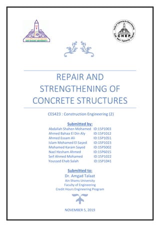
- 16. 15| P a g e Case Study (3) IndiaŌĆōNehru Memorial College :Introduction.3.1 A survey was conducted by Canada Mortgage and Housing Corporation in the city of Toronto to develop a better understanding of the condition of existing high-rise buildings in order to determine the more cost-effective repair methods. The survey indicated that the average cost/unit for repairs over 10 years was approximately four lakh rupees for all work, excluding regular maintenance items such as interior finishes. This amount is equal approximately to one month's rent per year. It was found out that water penetration and air leakage through the building envelope was the main cause which resulted in structural and other damage. The condition in other metro cities will be more or less similar and cost will be even higher in costal cities associated with severe environmental distresses. Repair materials and methodology will be similar for any type of concrete structures either a low or a high-rise building. To study the distress and its repair methodology, an Institution building in a costal environment which was repaired and rehabilitated was selected as a case study. 3.2.Distress Observed: Since the building was very old and located in a marine climate, the water leakages and reinforcement corrosion were major issues. There were leakages in the roof and water seepage through the external walls. The walls were made of laterite stone block masonry. The pointings of the stone masonry were disintegrated and water was leaking through these joints. There were spalling of plaster, cracks in the masonry walls and also cracks in the ceilings of the RCC roof. The water seepages and leakages led to growth of fungus and mosses on the walls and the ceilings.
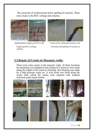
- 17. 16| P a g e The corrosion of reinforcement led to spalling of concrete. There were cracks in the RCC ceilings and columns. Spalled plaster, fungus growth in walls Cracks in the ceiling and masonry wall Fungal growth in ceilings Corrosion and spalling of concrete in columns 3.3.Repair of Cracks in Masonary walls: There were some cracks in the masonry walls. At those locations the plastering was chipped of and cutting of V-grooves were made along the length of the crack by chiseling. The cleaning was made by a high pressure water jet. A wire mesh was fixed along the cracks after which the cracks were repaired with medium structural grade repair mortar.
- 18. 17| P a g e Repair and Strengthening of RCC Columns.3.4 :Beams and Slabs, The reinforcements in the most of the columns were corroded. There was complete loss of cover concrete in some columns. The following steps were taken: ŌĆó Distress and spalled concrete portions were identified and marked for repair and restoration. ŌĆó Reinforcements were exposed by chiseling properly with light weight hammer and chisel. ŌĆó The exposed reinforcements were properly cleaned by wire brushed and entire concrete and steel surface were washed with potable water. ŌĆó Thereafter the reinforcements were applied with a rust remover and rubbed with gunny sacks, wiped properly and washed with high pressure water jet to wash out the traces of any residues. ŌĆó Then the same reinforcements were applied with anti-corrosive epoxy zinc primer to prevent further corrosion. ŌĆó After that the distressed concrete portions were properly applied with epoxy bonding agent for acting as an impervious layer to restoration patch. ŌĆó Finally a cementitious high structural grade repair material was applied in mortar consistency to build the thickness of the cover concrete as needed at site condition. The ceiling surface of roof slab and beam were also repaired in the similar manner.
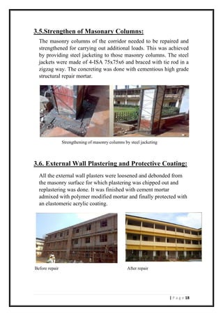
- 19. 18| P a g e 3.5.Strengthen of Masonary Columns: The masonry columns of the corridor needed to be repaired and strengthened for carrying out additional loads. This was achieved by providing steel jacketing to those masonry columns. The steel jackets were made of 4-ISA 75x75x6 and braced with tie rod in a zigzag way. The concreting was done with cementious high grade structural repair mortar. Strengthening of masonry columns by steel jacketing 3.6. External Wall Plastering and Protective Coating: All the external wall plasters were loosened and debonded from the masonry surface for which plastering was chipped out and replastering was done. It was finished with cement mortar admixed with polymer modified mortar and finally protected with an elastomeric acrylic coating. Before repair After repair