際際滷

際際滷Share a Scribd company logo
Final Presentation


 Ankit Master
 Spring 2009
   Couplers/Dividers
       Branch Line Coupler
       Wilkinson Coupler
       Modified Wilkinson Coupler
       Ratrace Coupler
   Gain Block
   Low Noise Amplifier
   Oscillator
- Branchline couplers are 3 dB
  directional couplers
- The power fed at the input
  port is divided equally
  between the two output ports.
- However, there is a 90-degree
  phase difference in the output
  of the two ports
S- parameters     Magnitude (dB)
                             (@ 2.4 GHz)    simulated   measured
                                 S11          -30.03     -14.55
                                 S12          -2.97       -2.97
                                 S21          -2.97       -3.02
                                 S22          -30.03     -15.16
                                 S13          -3.05       -4.06
                                 S31          -3.05       -4.15


Phase Difference between outputs obtained on ports 2 and 3:
SIMULATED: 89.890
MEASURED: 91.000
S11                                       S12


 S21                                          S22
       Branch line Coupler: Magnitude plots
S13   Branch line Coupler: Magnitude plots   S31


                     S12  S13
          Branch line Coupler: Phase plot
- It is a n-port network
  commonly used for
  combining and splitting
  power.
- This circuit achieves
isolation at the output
ports while maintaining
matched condition on all
ports.
S- parameters     Magnitude (dB)
                             (@ 2.4 GHz)    simulated   measured
                                 S11          -20.01     -25.56
                                 S12          -3.05       -3.10
                                 S21          -3.05       -3.53
                                 S22          -26.26     -11.08
                                 S13          -3.05       -2.98
                                 S31          -3.05       -3.33


Phase Difference between outputs obtained on ports 2 and 3:
SIMULATED: 0.000
MEASURED: -1.480
S11                                         S12


 S21                                         S22
       Wilkinson Coupler: Magnitude plots
S13   Wilkinson Coupler: Magnitude plots   S31


                    S12  S13
          Wilkinson Coupler: Phase plot
RF circuit design using ADS
S- parameters     Magnitude (dB)
                             (@ 2.4 GHz)    simulated   measured
                                 S11          -38.28     -14.08
                                 S12          -3.01       -3.36
                                 S21          -3.01       -3.51
                                 S22          -41.85     -12.21
                                 S13          -3.01       -3.23
                                 S31          -3.01       -3.33


Phase Difference between outputs obtained on ports 2 and 3:
SIMULATED: 0.000
MEASURED: 0.8750
S11                                     S12


 S21                                       S22
   Modified Wilkinson Coupler: Magnitude plots
S13   Modified Wilkinson Coupler: Magnitude plots   S31


                         S12  S13
          Modified Wilkinson Coupler: Phase plot
RF circuit design using ADS
-This is a hybrid coupler
- Like the Quadrature
hybrid, the ratrace coupler
is a 3-dB directional
coupler
-180-degree phase
difference between output
ports
S- parameters     Magnitude (dB)
 (@ 2.4 GHz)    simulated   measured
    S11           -39.21     -12.19
    S12           -3.00       -3.57
    S21           -3.00       -3.64
    S22          -39. 22     -13.11
    S13           -39.58     -40.36
    S31           -39.58     -40.45
    S14           -3.01       -3.20
    S41           -3.01       -3.34
S11                                        S12


 S21                                        S22
       Rat Race Coupler: Magnitude plots
S13                                        S31


 S14                                        S41
       Rat Race Coupler: Magnitude plots
S12-S13                                          S12-S14
                   Rat Race Coupler: Phase plot


Phase Difference between outputs obtained at ports 2 and 3:
SIMULATED: - 0.180
MEASURED: -36.380

Phase Difference between outputs obtained at ports 2 and 4:
SIMULATED: - 178.800
MEASURED: - 172.810
-Active circuit which uses transistors to amplify the wea
input signal
-Device used: 2SEC5009
RF circuit design using ADS
S- parameters      Magnitude (dB)

 (@ 2.4 GHz)    simulated   measured
    S11          -18.999     -24.398
    S21           6.354       3.893
    S22           -19.00     -13.428
  StabFact        1.004         -
-Low Noise amplifier is necessary at the input of a receiver
to amplify the weak received signal with minimium
amplification of noise
-Device used: AT32011
Layout of the LNA in ADS


Actual fabricated circuit
Noise Figure   S-parameters
RF circuit design using ADS
S- parameters      Magnitude (dB)

 (@ 2.4 GHz)    simulated   measured

    S11          -10.475      -6.031

    S12          -16.603     -17.940

    S21           12.042     10.022

    S22          -57.434     -54.278

  StabFact        1.065         -

  NF min          1.961         -

    nf(2)         2.069         -

 Max Gain         12.762        -
-A local oscillator is used to combine the baseband signal
with a high frequency RF signal during modulation
- Device used: ATF33143
Layout in ADS


Actual fabricated circuit
(Apologies for the poor image quality)
RF circuit design using ADS
Harmo      simulated            measured
 nic
index
        HB.freq   HB.vout   HB.freq   HB.vout
        (GHz)     (dBm)     (GHz)     (dBm)

  1      2.381     20.480    2.5975    10.02

  2      4.761    -13.560    5.2075    -10.23

  3      7.142     -3.331    7.7950    -21.43

S11 @    4.751       -         -         -
 2.35     dB
GHz
- ADS is a very useful and powerful tool for building
circuits
- Reducing the number of parameters during
optimization improves the chances of reaching the
desired goal efficiently
- Selection of a proper device is essential during the
initial stages of the design to avoid complications in the
latter stages of the project
- Tuning is not as convenient as optimization
RF circuit design using ADS

More Related Content

What's hot (20)

Clock jitter
Clock jitterClock jitter
Clock jitter
Maj. Sanjaya Prasad
RF Circuit Design - [Ch4-1] Microwave Transistor Amplifier
RF Circuit Design - [Ch4-1] Microwave Transistor AmplifierRF Circuit Design - [Ch4-1] Microwave Transistor Amplifier
RF Circuit Design - [Ch4-1] Microwave Transistor Amplifier
Simen Li
Low noise amplifier
Low noise amplifierLow noise amplifier
Low noise amplifier
Vinay Krishna Vadlamudi
Network analysis of rf and microwave circuits
Network analysis of rf and microwave circuitsNetwork analysis of rf and microwave circuits
Network analysis of rf and microwave circuits
Shankar Gangaju
Class b amplifier
Class b amplifierClass b amplifier
Class b amplifier
Gauravsinh Parmar
Phase-locked Loops - Theory and Design
Phase-locked Loops - Theory and DesignPhase-locked Loops - Theory and Design
Phase-locked Loops - Theory and Design
Simen Li
Altera flex
Altera flexAltera flex
Altera flex
Sharmil Nila
RF Module Design - [Chapter 5] Low Noise Amplifier
RF Module Design - [Chapter 5]  Low Noise AmplifierRF Module Design - [Chapter 5]  Low Noise Amplifier
RF Module Design - [Chapter 5] Low Noise Amplifier
Simen Li
Distributed rc Model
Distributed rc ModelDistributed rc Model
Distributed rc Model
VARUN KUMAR
Signal Integrity - A Crash Course [R Lott]
Signal Integrity - A Crash Course [R Lott]Signal Integrity - A Crash Course [R Lott]
Signal Integrity - A Crash Course [R Lott]
Ryan Lott
Power Divider
Power DividerPower Divider
Power Divider
Yong Heui Cho
PAPR Reduction
PAPR ReductionPAPR Reduction
PAPR Reduction
Pei-Che Chang
Directional couplers ppt for microwave engineering
Directional couplers  ppt for microwave engineeringDirectional couplers  ppt for microwave engineering
Directional couplers ppt for microwave engineering
Divya Shree
Eye diagram in Communication
Eye diagram in CommunicationEye diagram in Communication
Eye diagram in Communication
Sivanesh M
Wideband CMOS Power Amplifiers Design at mm-Wave: Challenges and Case Studies
Wideband CMOS Power Amplifiers Design at mm-Wave: Challenges and Case StudiesWideband CMOS Power Amplifiers Design at mm-Wave: Challenges and Case Studies
Wideband CMOS Power Amplifiers Design at mm-Wave: Challenges and Case Studies
aiclab
lecture5.ppt
lecture5.pptlecture5.ppt
lecture5.ppt
ssuserb4d806
Multiband Transceivers - [Chapter 2] Noises and Linearities
Multiband Transceivers - [Chapter 2]  Noises and LinearitiesMultiband Transceivers - [Chapter 2]  Noises and Linearities
Multiband Transceivers - [Chapter 2] Noises and Linearities
Simen Li
Multiband Transceivers - [Chapter 6] Multi-mode and Multi-band Transceivers
Multiband Transceivers - [Chapter 6] Multi-mode and Multi-band TransceiversMultiband Transceivers - [Chapter 6] Multi-mode and Multi-band Transceivers
Multiband Transceivers - [Chapter 6] Multi-mode and Multi-band Transceivers
Simen Li
IC Design of Power Management Circuits (II)
IC Design of Power Management Circuits (II)IC Design of Power Management Circuits (II)
IC Design of Power Management Circuits (II)
Claudia Sin
Relationships Among EVM, BER and SNR + WiFi minimum SNR consideration
Relationships Among EVM, BER and SNR + WiFi minimum SNR considerationRelationships Among EVM, BER and SNR + WiFi minimum SNR consideration
Relationships Among EVM, BER and SNR + WiFi minimum SNR consideration
Pei-Che Chang
RF Circuit Design - [Ch4-1] Microwave Transistor Amplifier
RF Circuit Design - [Ch4-1] Microwave Transistor AmplifierRF Circuit Design - [Ch4-1] Microwave Transistor Amplifier
RF Circuit Design - [Ch4-1] Microwave Transistor Amplifier
Simen Li
Network analysis of rf and microwave circuits
Network analysis of rf and microwave circuitsNetwork analysis of rf and microwave circuits
Network analysis of rf and microwave circuits
Shankar Gangaju
Phase-locked Loops - Theory and Design
Phase-locked Loops - Theory and DesignPhase-locked Loops - Theory and Design
Phase-locked Loops - Theory and Design
Simen Li
RF Module Design - [Chapter 5] Low Noise Amplifier
RF Module Design - [Chapter 5]  Low Noise AmplifierRF Module Design - [Chapter 5]  Low Noise Amplifier
RF Module Design - [Chapter 5] Low Noise Amplifier
Simen Li
Distributed rc Model
Distributed rc ModelDistributed rc Model
Distributed rc Model
VARUN KUMAR
Signal Integrity - A Crash Course [R Lott]
Signal Integrity - A Crash Course [R Lott]Signal Integrity - A Crash Course [R Lott]
Signal Integrity - A Crash Course [R Lott]
Ryan Lott
Directional couplers ppt for microwave engineering
Directional couplers  ppt for microwave engineeringDirectional couplers  ppt for microwave engineering
Directional couplers ppt for microwave engineering
Divya Shree
Eye diagram in Communication
Eye diagram in CommunicationEye diagram in Communication
Eye diagram in Communication
Sivanesh M
Wideband CMOS Power Amplifiers Design at mm-Wave: Challenges and Case Studies
Wideband CMOS Power Amplifiers Design at mm-Wave: Challenges and Case StudiesWideband CMOS Power Amplifiers Design at mm-Wave: Challenges and Case Studies
Wideband CMOS Power Amplifiers Design at mm-Wave: Challenges and Case Studies
aiclab
Multiband Transceivers - [Chapter 2] Noises and Linearities
Multiband Transceivers - [Chapter 2]  Noises and LinearitiesMultiband Transceivers - [Chapter 2]  Noises and Linearities
Multiband Transceivers - [Chapter 2] Noises and Linearities
Simen Li
Multiband Transceivers - [Chapter 6] Multi-mode and Multi-band Transceivers
Multiband Transceivers - [Chapter 6] Multi-mode and Multi-band TransceiversMultiband Transceivers - [Chapter 6] Multi-mode and Multi-band Transceivers
Multiband Transceivers - [Chapter 6] Multi-mode and Multi-band Transceivers
Simen Li
IC Design of Power Management Circuits (II)
IC Design of Power Management Circuits (II)IC Design of Power Management Circuits (II)
IC Design of Power Management Circuits (II)
Claudia Sin
Relationships Among EVM, BER and SNR + WiFi minimum SNR consideration
Relationships Among EVM, BER and SNR + WiFi minimum SNR considerationRelationships Among EVM, BER and SNR + WiFi minimum SNR consideration
Relationships Among EVM, BER and SNR + WiFi minimum SNR consideration
Pei-Che Chang

Viewers also liked (20)

Microwave- directional coupler paramets & applications
Microwave- directional coupler paramets & applicationsMicrowave- directional coupler paramets & applications
Microwave- directional coupler paramets & applications
JETISH
180 hybrid-coupler
180 hybrid-coupler180 hybrid-coupler
180 hybrid-coupler
Ahmad Mahfouz
Fundamentals of the RF Transmission and Reception of Digital Signals
Fundamentals of the RF Transmission and Reception of Digital SignalsFundamentals of the RF Transmission and Reception of Digital Signals
Fundamentals of the RF Transmission and Reception of Digital Signals
Analog Devices, Inc.
A Glimpse into Developing Software-Defined Radio by Python
A Glimpse into Developing Software-Defined Radio by PythonA Glimpse into Developing Software-Defined Radio by Python
A Glimpse into Developing Software-Defined Radio by Python
Albert Huang
Microwave Coupler
Microwave CouplerMicrowave Coupler
Microwave Coupler
rf辰n ngin辿
3D Smith Chart
3D Smith Chart3D Smith Chart
3D Smith Chart
Corporaci坦n El辿ctrica del Ecuador, CELEC EP
Distributed amplifier
Distributed amplifierDistributed amplifier
Distributed amplifier
Mohammad Bahrami
Conference ppt
Conference pptConference ppt
Conference ppt
Satish Kumar
1127799303485
11277993034851127799303485
1127799303485
5045033
Microwave Devices Lecture11
Microwave Devices Lecture11Microwave Devices Lecture11
Microwave Devices Lecture11
Amr Al-Awamry
Pcb circuit design for a gate driver
Pcb circuit design for a gate driverPcb circuit design for a gate driver
Pcb circuit design for a gate driver
pcbprototype
Unit iii mirowave passive components
Unit iii mirowave passive componentsUnit iii mirowave passive components
Unit iii mirowave passive components
VELAMMAL ENGINEERING COLLEGE
Circuit Design
Circuit DesignCircuit Design
Circuit Design
luckygal
Microwave Engineering - Homework
Microwave Engineering - HomeworkMicrowave Engineering - Homework
Microwave Engineering - Homework
H畉i Nguy畛n H畛 B叩
Microwave devices
Microwave devicesMicrowave devices
Microwave devices
john chezhiyan r
Experiences in Digital Circuit Design Courses: A Self-Study Platform for Lear...
Experiences in Digital Circuit Design Courses: A Self-Study Platform for Lear...Experiences in Digital Circuit Design Courses: A Self-Study Platform for Lear...
Experiences in Digital Circuit Design Courses: A Self-Study Platform for Lear...
UOC Universitat Oberta de Catalunya
219272664 s-parameters
219272664 s-parameters219272664 s-parameters
219272664 s-parameters
Manish Arora
Rectangular waveguides
Rectangular waveguidesRectangular waveguides
Rectangular waveguides
khan yaseen
An Introduction to RF Design, Live presentation at EELive 2014
An Introduction to RF Design, Live presentation at EELive 2014An Introduction to RF Design, Live presentation at EELive 2014
An Introduction to RF Design, Live presentation at EELive 2014
Rohde & Schwarz North America
Successive Approximation ADC
Successive Approximation ADCSuccessive Approximation ADC
Successive Approximation ADC
ankit_master
Microwave- directional coupler paramets & applications
Microwave- directional coupler paramets & applicationsMicrowave- directional coupler paramets & applications
Microwave- directional coupler paramets & applications
JETISH
180 hybrid-coupler
180 hybrid-coupler180 hybrid-coupler
180 hybrid-coupler
Ahmad Mahfouz
Fundamentals of the RF Transmission and Reception of Digital Signals
Fundamentals of the RF Transmission and Reception of Digital SignalsFundamentals of the RF Transmission and Reception of Digital Signals
Fundamentals of the RF Transmission and Reception of Digital Signals
Analog Devices, Inc.
A Glimpse into Developing Software-Defined Radio by Python
A Glimpse into Developing Software-Defined Radio by PythonA Glimpse into Developing Software-Defined Radio by Python
A Glimpse into Developing Software-Defined Radio by Python
Albert Huang
1127799303485
11277993034851127799303485
1127799303485
5045033
Microwave Devices Lecture11
Microwave Devices Lecture11Microwave Devices Lecture11
Microwave Devices Lecture11
Amr Al-Awamry
Pcb circuit design for a gate driver
Pcb circuit design for a gate driverPcb circuit design for a gate driver
Pcb circuit design for a gate driver
pcbprototype
Circuit Design
Circuit DesignCircuit Design
Circuit Design
luckygal
Experiences in Digital Circuit Design Courses: A Self-Study Platform for Lear...
Experiences in Digital Circuit Design Courses: A Self-Study Platform for Lear...Experiences in Digital Circuit Design Courses: A Self-Study Platform for Lear...
Experiences in Digital Circuit Design Courses: A Self-Study Platform for Lear...
UOC Universitat Oberta de Catalunya
219272664 s-parameters
219272664 s-parameters219272664 s-parameters
219272664 s-parameters
Manish Arora
Rectangular waveguides
Rectangular waveguidesRectangular waveguides
Rectangular waveguides
khan yaseen
An Introduction to RF Design, Live presentation at EELive 2014
An Introduction to RF Design, Live presentation at EELive 2014An Introduction to RF Design, Live presentation at EELive 2014
An Introduction to RF Design, Live presentation at EELive 2014
Rohde & Schwarz North America
Successive Approximation ADC
Successive Approximation ADCSuccessive Approximation ADC
Successive Approximation ADC
ankit_master

Similar to RF circuit design using ADS (20)

Thesis presentation
Thesis presentationThesis presentation
Thesis presentation
Jonathan Chik
Comparison of time-domain S-parameters of RG58 cable computed by Theory, CST,...
Comparison of time-domain S-parameters of RG58 cable computed by Theory, CST,...Comparison of time-domain S-parameters of RG58 cable computed by Theory, CST,...
Comparison of time-domain S-parameters of RG58 cable computed by Theory, CST,...
Piero Belforte
Rg58 s par theory cst_spice_dws_final
Rg58 s par theory cst_spice_dws_finalRg58 s par theory cst_spice_dws_final
Rg58 s par theory cst_spice_dws_final
Piero Belforte
Uhf si ge hbt amplifier parameters and noise characteristics
Uhf si ge hbt amplifier parameters and noise characteristicsUhf si ge hbt amplifier parameters and noise characteristics
Uhf si ge hbt amplifier parameters and noise characteristics
mohamed albanna
Lect2 up290 (100328)
Lect2 up290 (100328)Lect2 up290 (100328)
Lect2 up290 (100328)
aicdesign
B0160709
B0160709B0160709
B0160709
IOSR Journals
B0160709
B0160709B0160709
B0160709
IOSR Journals
Equal Split Wilkinson Power Divider - Project Presentation
Equal Split Wilkinson Power Divider - Project PresentationEqual Split Wilkinson Power Divider - Project Presentation
Equal Split Wilkinson Power Divider - Project Presentation
Bhanwar Singh Meena
Tdr measurement of rg58 coaxial cable s parameters 120413
Tdr measurement of rg58 coaxial cable s parameters 120413Tdr measurement of rg58 coaxial cable s parameters 120413
Tdr measurement of rg58 coaxial cable s parameters 120413
Piero Belforte
Digital to Analog Conversion
Digital to Analog ConversionDigital to Analog Conversion
Digital to Analog Conversion
Soumen Santra
Introduction to microwaves
Introduction to microwavesIntroduction to microwaves
Introduction to microwaves
Tapas Mondal
3 p8 1522
3 p8 15223 p8 1522
3 p8 1522
University of Technology
171220027 Kaushal Verma.pdf
171220027 Kaushal Verma.pdf171220027 Kaushal Verma.pdf
171220027 Kaushal Verma.pdf
saiusa5444
Design of Low Noise Amplifier for Wimax Application
Design of Low Noise Amplifier for Wimax ApplicationDesign of Low Noise Amplifier for Wimax Application
Design of Low Noise Amplifier for Wimax Application
IOSR Journals
Microwave
MicrowaveMicrowave
Microwave
yogesh parmar
PARASITIC-AWARE FULL PHYSICAL CHIP DESIGN OF LNA RFIC AT 2.45GHZ USING IBM 13...
PARASITIC-AWARE FULL PHYSICAL CHIP DESIGN OF LNA RFIC AT 2.45GHZ USING IBM 13...PARASITIC-AWARE FULL PHYSICAL CHIP DESIGN OF LNA RFIC AT 2.45GHZ USING IBM 13...
PARASITIC-AWARE FULL PHYSICAL CHIP DESIGN OF LNA RFIC AT 2.45GHZ USING IBM 13...
Ilango Jeyasubramanian
Ultra-low power 0.45 mW 2.4 GHz CMOS low noise amplifier for wireless sensor ...
Ultra-low power 0.45 mW 2.4 GHz CMOS low noise amplifier for wireless sensor ...Ultra-low power 0.45 mW 2.4 GHz CMOS low noise amplifier for wireless sensor ...
Ultra-low power 0.45 mW 2.4 GHz CMOS low noise amplifier for wireless sensor ...
journalBEEI
Narrowband_LNA
Narrowband_LNANarrowband_LNA
Narrowband_LNA
Nagarjun Bhat
Rsf electronik ms82_catalog
Rsf electronik ms82_catalogRsf electronik ms82_catalog
Rsf electronik ms82_catalog
Electromate
Rsf electronik ms82_catalog
Rsf electronik ms82_catalogRsf electronik ms82_catalog
Rsf electronik ms82_catalog
Electromate
Thesis presentation
Thesis presentationThesis presentation
Thesis presentation
Jonathan Chik
Comparison of time-domain S-parameters of RG58 cable computed by Theory, CST,...
Comparison of time-domain S-parameters of RG58 cable computed by Theory, CST,...Comparison of time-domain S-parameters of RG58 cable computed by Theory, CST,...
Comparison of time-domain S-parameters of RG58 cable computed by Theory, CST,...
Piero Belforte
Rg58 s par theory cst_spice_dws_final
Rg58 s par theory cst_spice_dws_finalRg58 s par theory cst_spice_dws_final
Rg58 s par theory cst_spice_dws_final
Piero Belforte
Uhf si ge hbt amplifier parameters and noise characteristics
Uhf si ge hbt amplifier parameters and noise characteristicsUhf si ge hbt amplifier parameters and noise characteristics
Uhf si ge hbt amplifier parameters and noise characteristics
mohamed albanna
Lect2 up290 (100328)
Lect2 up290 (100328)Lect2 up290 (100328)
Lect2 up290 (100328)
aicdesign
Equal Split Wilkinson Power Divider - Project Presentation
Equal Split Wilkinson Power Divider - Project PresentationEqual Split Wilkinson Power Divider - Project Presentation
Equal Split Wilkinson Power Divider - Project Presentation
Bhanwar Singh Meena
Tdr measurement of rg58 coaxial cable s parameters 120413
Tdr measurement of rg58 coaxial cable s parameters 120413Tdr measurement of rg58 coaxial cable s parameters 120413
Tdr measurement of rg58 coaxial cable s parameters 120413
Piero Belforte
Digital to Analog Conversion
Digital to Analog ConversionDigital to Analog Conversion
Digital to Analog Conversion
Soumen Santra
Introduction to microwaves
Introduction to microwavesIntroduction to microwaves
Introduction to microwaves
Tapas Mondal
171220027 Kaushal Verma.pdf
171220027 Kaushal Verma.pdf171220027 Kaushal Verma.pdf
171220027 Kaushal Verma.pdf
saiusa5444
Design of Low Noise Amplifier for Wimax Application
Design of Low Noise Amplifier for Wimax ApplicationDesign of Low Noise Amplifier for Wimax Application
Design of Low Noise Amplifier for Wimax Application
IOSR Journals
PARASITIC-AWARE FULL PHYSICAL CHIP DESIGN OF LNA RFIC AT 2.45GHZ USING IBM 13...
PARASITIC-AWARE FULL PHYSICAL CHIP DESIGN OF LNA RFIC AT 2.45GHZ USING IBM 13...PARASITIC-AWARE FULL PHYSICAL CHIP DESIGN OF LNA RFIC AT 2.45GHZ USING IBM 13...
PARASITIC-AWARE FULL PHYSICAL CHIP DESIGN OF LNA RFIC AT 2.45GHZ USING IBM 13...
Ilango Jeyasubramanian
Ultra-low power 0.45 mW 2.4 GHz CMOS low noise amplifier for wireless sensor ...
Ultra-low power 0.45 mW 2.4 GHz CMOS low noise amplifier for wireless sensor ...Ultra-low power 0.45 mW 2.4 GHz CMOS low noise amplifier for wireless sensor ...
Ultra-low power 0.45 mW 2.4 GHz CMOS low noise amplifier for wireless sensor ...
journalBEEI
Rsf electronik ms82_catalog
Rsf electronik ms82_catalogRsf electronik ms82_catalog
Rsf electronik ms82_catalog
Electromate
Rsf electronik ms82_catalog
Rsf electronik ms82_catalogRsf electronik ms82_catalog
Rsf electronik ms82_catalog
Electromate

RF circuit design using ADS

  • 1. Final Presentation Ankit Master Spring 2009
  • 2. Couplers/Dividers Branch Line Coupler Wilkinson Coupler Modified Wilkinson Coupler Ratrace Coupler Gain Block Low Noise Amplifier Oscillator
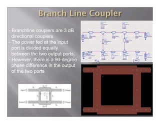
  • 3. - Branchline couplers are 3 dB directional couplers - The power fed at the input port is divided equally between the two output ports. - However, there is a 90-degree phase difference in the output of the two ports
  • 4. S- parameters Magnitude (dB) (@ 2.4 GHz) simulated measured S11 -30.03 -14.55 S12 -2.97 -2.97 S21 -2.97 -3.02 S22 -30.03 -15.16 S13 -3.05 -4.06 S31 -3.05 -4.15 Phase Difference between outputs obtained on ports 2 and 3: SIMULATED: 89.890 MEASURED: 91.000
  • 5. S11 S12 S21 S22 Branch line Coupler: Magnitude plots
  • 6. S13 Branch line Coupler: Magnitude plots S31 S12 S13 Branch line Coupler: Phase plot
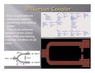
  • 7. - It is a n-port network commonly used for combining and splitting power. - This circuit achieves isolation at the output ports while maintaining matched condition on all ports.
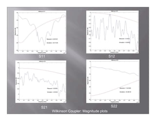
  • 8. S- parameters Magnitude (dB) (@ 2.4 GHz) simulated measured S11 -20.01 -25.56 S12 -3.05 -3.10 S21 -3.05 -3.53 S22 -26.26 -11.08 S13 -3.05 -2.98 S31 -3.05 -3.33 Phase Difference between outputs obtained on ports 2 and 3: SIMULATED: 0.000 MEASURED: -1.480
  • 9. S11 S12 S21 S22 Wilkinson Coupler: Magnitude plots
  • 10. S13 Wilkinson Coupler: Magnitude plots S31 S12 S13 Wilkinson Coupler: Phase plot
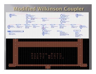
  • 12. S- parameters Magnitude (dB) (@ 2.4 GHz) simulated measured S11 -38.28 -14.08 S12 -3.01 -3.36 S21 -3.01 -3.51 S22 -41.85 -12.21 S13 -3.01 -3.23 S31 -3.01 -3.33 Phase Difference between outputs obtained on ports 2 and 3: SIMULATED: 0.000 MEASURED: 0.8750
  • 13. S11 S12 S21 S22 Modified Wilkinson Coupler: Magnitude plots
  • 14. S13 Modified Wilkinson Coupler: Magnitude plots S31 S12 S13 Modified Wilkinson Coupler: Phase plot
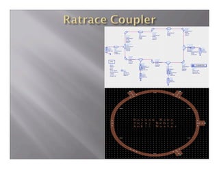
  • 17. -This is a hybrid coupler - Like the Quadrature hybrid, the ratrace coupler is a 3-dB directional coupler -180-degree phase difference between output ports
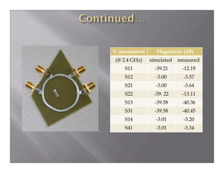
  • 18. S- parameters Magnitude (dB) (@ 2.4 GHz) simulated measured S11 -39.21 -12.19 S12 -3.00 -3.57 S21 -3.00 -3.64 S22 -39. 22 -13.11 S13 -39.58 -40.36 S31 -39.58 -40.45 S14 -3.01 -3.20 S41 -3.01 -3.34
  • 19. S11 S12 S21 S22 Rat Race Coupler: Magnitude plots
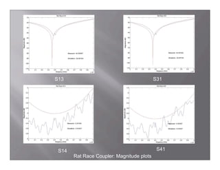
  • 20. S13 S31 S14 S41 Rat Race Coupler: Magnitude plots
  • 21. S12-S13 S12-S14 Rat Race Coupler: Phase plot Phase Difference between outputs obtained at ports 2 and 3: SIMULATED: - 0.180 MEASURED: -36.380 Phase Difference between outputs obtained at ports 2 and 4: SIMULATED: - 178.800 MEASURED: - 172.810
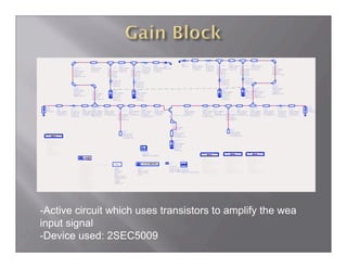
  • 22. -Active circuit which uses transistors to amplify the wea input signal -Device used: 2SEC5009
  • 25. S- parameters Magnitude (dB) (@ 2.4 GHz) simulated measured S11 -18.999 -24.398 S21 6.354 3.893 S22 -19.00 -13.428 StabFact 1.004 -
  • 26. -Low Noise amplifier is necessary at the input of a receiver to amplify the weak received signal with minimium amplification of noise -Device used: AT32011
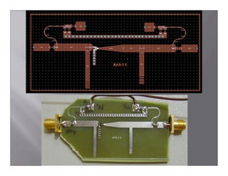
  • 27. Layout of the LNA in ADS Actual fabricated circuit
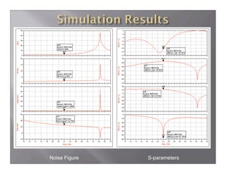
  • 28. Noise Figure S-parameters
  • 30. S- parameters Magnitude (dB) (@ 2.4 GHz) simulated measured S11 -10.475 -6.031 S12 -16.603 -17.940 S21 12.042 10.022 S22 -57.434 -54.278 StabFact 1.065 - NF min 1.961 - nf(2) 2.069 - Max Gain 12.762 -
  • 31. -A local oscillator is used to combine the baseband signal with a high frequency RF signal during modulation - Device used: ATF33143
  • 32. Layout in ADS Actual fabricated circuit (Apologies for the poor image quality)
  • 34. Harmo simulated measured nic index HB.freq HB.vout HB.freq HB.vout (GHz) (dBm) (GHz) (dBm) 1 2.381 20.480 2.5975 10.02 2 4.761 -13.560 5.2075 -10.23 3 7.142 -3.331 7.7950 -21.43 S11 @ 4.751 - - - 2.35 dB GHz
  • 35. - ADS is a very useful and powerful tool for building circuits - Reducing the number of parameters during optimization improves the chances of reaching the desired goal efficiently - Selection of a proper device is essential during the initial stages of the design to avoid complications in the latter stages of the project - Tuning is not as convenient as optimization