


More Related Content
Similar to Rock dynamics-presentation -javid.pdf (20)
Recently uploaded (20)


Rock dynamics-presentation -javid.pdf
- 1. Rock Dynamics Lecture Topics: Concepts of 1-Strain energy 2-Wave Equations 3- Blast Waves 4- Wave Propagation in continuous and Discontinuous media Mid term presentation Presented by: Abdolhakim Javid
- 3. STRAIN ENERGY Introduction ŌĆó The concept of strain energy is particularly useful in the determination of the effects of impact loadings on structures or machine components. ŌĆó The strain-energy density of a material will be defined. ŌĆó strain energy of a member will be defined as the increase in energy associated with the deformation of the member. ŌĆó strain energy is equal to the work done by a slowly increasing load applied to the member. Consider a rod BC of length L and uniform cross-sectional area A, which is attached at B to a fixed support, and subjected at C to a slowly increasing axial load P . (Fig. 1)
- 4. STRAIN ENERGY Let us now consider the work dU done by the load P as the rod elongates by a small amount dx. This elementary work is equal to the product of the magnitude P of the load and of the small elongation dx. We write: and note that the expression obtained is equal to the element of area of width dx located under the load-deformation diagram. The total work U done by the load as the rod undergoes a deformation x1 is thus and is equal to the area under the load-deformation diagram between x =0 and x =x1. ØææØæł = ØæāØææØæź = ØæÆØæÖØæÆØæÜØæÆØæøØæĪØæÄØæ¤Øæ” ØæżØæ£Øæ¤Øæś Øæł = ÓČ▒ 0 Øæź1 Øæā ØææØæź = ØæĪØæ£ØæĪØæÄØæÖ ØæżØæ£Øæ¤Øæś (Fig. 2) Eq. (1)
- 5. STRAIN ENERGY The work done by the load P as it is slowly applied to the rod must result in the increase of some energy associated with the deformation of the rod. This energy is referred to as the strain energy of the rod. We have, by definition, In the case of a linear and elastic deformation, the portion of the load-deformation diagram involved can be represented by a straight line of equation P=kx (Fig. 3). Substituting for P in Eq.(1), we have where P1 is the value of the load corresponding to the deformation x1. Øæł = ÓČ▒ 0 Øæź1 Øæā ØææØæź = ØæĪØæ£ØæĪØæÄØæÖ ØæżØæ£Øæ¤Øæś = ØæĀØæĪØæ¤ØæÄØæ¢Øæø ØæÆØæøØæÆØæ¤ØæöØæ” Øæł = ÓČ▒ 0 Øæź1 ØæśØæźØææØæź = 1 2 ØæśØæź1 2 = 1 2 Øæā1Øæź1 (Fig. 3) Eq. (1) Eq. (2)
- 6. STRAIN ENERGY Density As the load-deformation diagram for a rod BC depends upon the length L and the cross-sectional area A of the rod. The strain energy U defined by Eq. (1), therefore, will also depend upon the dimensions of the rod. In order to eliminate the effect of size from our discussion and direct our attention to the properties of the material, the strain energy per unit volume will be considered. Dividing the strain energy U by the volume V =AL of the rod (Fig.1), and using Eq. (1), we have: Recalling that P/A represents the normal stress Žāx in the rod, and x/L the normal strain ╬Ąx, we write: The strain-energy density of a material will be defined as ŌĆ£ Strain energy per unit volumeŌĆØ Øæł Øæē = ÓČ▒ 0 Øæź1 Øæā ØÉ┤ ØææØæź ØÉ┐ Øæó = ÓČ▒ 0 Ø£Ć1 Ø£ÄØæź ØææØ£ĆØæź = strain energy density where ╬Ą1 denotes the value of the strain corresponding to the elongation x1. The strain energy per unit volume, U/V, is referred to as the strain-energy density and will be denoted by the letter u. We have, therefore: if SI metric units are used, the strain-energy density is expressed in J/m3 or its multiples kJ/m3 and MJ/m3 Eq. (3)
- 7. STRAIN ENERGY Density Referring to Fig. 4, we note that the strain-energy density u is equal to the area under the stress-strain curve, measured from ╬Ąx =0 to ╬Ąx= ╬Ą1. If the material is unloaded, the stress returns to zero, but there is a permanent deformation represented by the strain ╬Ąp, and only the portion of the strain energy per unit volume corresponding to the triangular area is recovered. The remainder of the energy spent in deforming the material is dissipated in the form of heat. it will be seen that it is equal to ŌĆ£area under the stress-strain diagram of the material.ŌĆØ (Fig. 4)
- 8. Modulus of Toughness The value of the strain-energy density obtained by setting ╬Ąx = ╬ĄR . where ╬ĄR is the strain at rupture, is known as the modulus of toughness of the material . It is equal to the area under the entire stress- strain diagram (Fig. 5) and represents the energy per unit volume required to cause the material to rupture. It is clear that the toughness of a material is related to ŌĆó its ductility as well as ŌĆó to its ultimate strength (Fig. 5)
- 9. Modulus of Resilience The modulus of resilience is equal to the area under the straight-line portion OY of the stress-strain diagram (Fig. 6) and represents the energy per unit volume that the material can absorb without yielding. The capacity of a structure to withstand an impact load without being permanently deformed clearly depends upon the resilience of the material used. Since the modulus of toughness and the modulus of resilience represent characteristic values of the strain-energy density of the material considered, they are both expressed in J/m3 (Fig. 6)
- 10. Modulus of Resilience If the stress Žāx remains within the proportional limit of the material, HookeŌĆÖs law applies and we write The value uY of the strain-energy density obtained by setting Žāx =ŽāY where is ŽāY the yield strength, is called the modulus of resilience of the material. We have Øæó = ÓČ▒ 0 Ø£Ć1 ØÉĖØ£ĆØæź ØææØ£ĆØæź = ØÉĖØ£Ć1 2 2 = Ø£Ä1 2 2ØÉĖ ØæóØæī = Ø£ÄØæī 2 2ØÉĖ = modulus of resilience Eq. (4) Ø£ÄØæź = ØÉĖØ£ĆØæź
- 11. 2-Wave Equations Theory of Elasticity Rock Dynamics
- 15. Ō¢½ Primary wave Ō¢½ compressional wave Ō¢½ Longitudinal wave Ō¢½ Dilatation wave Ō¢½ Irrotational wave Longitudinal Waves
- 16. Transverse Waves Ō¢½ Secondary wave Ō¢½ Shear wave Ō¢½ Rotational wave Ō¢½ Transvers wave
- 20. A seismograph, or seismometer, is an instrument used to detect and record seismic waves. Seismic waves are propagating vibrations that carry energy from the source of an earthquake outward in all directions.
- 21. Theory of Elasticity ŌĆó Seismic waves are stress (mechanical) waves that are generated as a response to acting on a material by a force. ŌĆó The force that generates this stress comes from a source of seismic energy such artificial (dynamite, ... etc) or natural earthquakes. ŌĆó The stress will produce strain (deformation) in the material relating to elasticity theory. ŌĆó Therefore, we need to study a little bit of elasticity theory in order to better understand the theory of seismic waves.
- 22. Stress ŌĆó There should be a maximum of 9 stress components associated with every possible combination of the coordinate system axes (’ü│xx, ’ü│xy, ’ü│xz, ’ü│yx, ’ü│yy, ’ü│yz, ’ü│zx, ’ü│zy, ’ü│zz). ŌĆó According to equilibrium (body is not moving but only deformed as a result of stress application): ’ü│ij = ’ü│ji, meaning that ’ü│xy = ’ü│yx, ’ü│yz = ’ü│zy, and ’ü│zx = ’ü│xz. ŌĆó If the force is perpendicular to the surface, we have a normal stress (’ü│xx, ’ü│yy, ’ü│zz); while if itŌĆÖs tangential to the surface, we have a shearing stress (’ü│xy, ’ü│yz, ’ü│xz).
- 23. Stress ŌĆó The stress matrix composed of nine components of the stress: Ø£Ä = Ø£ÄØæźØæź Ø£ÄØæźØæ” Ø£ÄØæźØæ¦ Ø£ÄØæ”Øæź Ø£ÄØæ”Øæ” Ø£ÄØæ”Øæ¦ Ø£ÄØæ¦Øæź Ø£ÄØæ¦Øæ” Ø£ÄØæ¦Øæ¦
- 24. Components of stress and strain ŌĆó If a stretching force is acting in the x-y plane and the corresponding motion is only occurred in the direction of x- axis, we will have the situation depicted in the corresponded figure. ŌĆó The point P moves a distance u to point PŌĆÖ after stretching while point Q moves a distance ux+’üäux to point QŌĆÖ. y x P Q PŌĆÖ QŌĆÖ ux ’üäx x x u u x x ’éČ + ’üä ’éČ
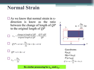
- 25. Normal Strain ’é© As we know that normal strain in x- direction is know as the ratio between the change of length of QP to the original length of QP ’é© ’é© ’é© ’é© y x P Q PŌĆÖ QŌĆÖ ux ’üäx Coordinates P(x,y) Q(x+’üäx,y) PŌĆÖ(x+u,y) ) , ( ' y x x x u u x Q x x ’üä + ’üä ’éČ ’éČ + + QP QP P Q QP of length original QP of length in change xx ŌłÆ = = ' ' ’üź u x x x x u u x P Q x + ŌłÆ ’üä + ’üä ’éČ ’éČ + + = ' ' x x x QP ŌłÆ ’üä + = x ux xx ’éČ ’éČ = ’üź Do similar processing for ’üźyy and ’üźzz. x x u u x x ’éČ + ’üä ’éČ
- 26. Shear Strain ŌĆó If a stretching force is acting in the x-y plane and the corresponding motion is induced either in the direction of x- axis and y-axis, we will have the situation depicted in the corresponded figure. ŌĆó The infinitesimal rectangular PQRS will have displaced and deformed into the diamond PŌĆÖQŌĆÖRŌĆÖSŌĆÖ. ŌĆó After stretching, points P, Q, S and R move to PŌĆÖ, QŌĆÖ, SŌĆÖ, and RŌĆÖ with coordinates. y x P Q PŌĆÖ QŌĆÖ ux ’üäx x x u u x x ’üä ’éČ ’éČ + S R SŌĆÖ RŌĆÖ x x u u y y ’üä ’éČ ’éČ + uy ’üäy y y x u x u ’üä ’éČ ’éČ +
- 27. Shear Strain ŌĆó The deformation in y coordinates in relative to x-axis is given by Coordinates P(x,y) PŌĆÖ(x+ux,y+uy) Q(x+’üäx,y) S(x,y+’üäy) ) , ( ' x x u u y x x x u u x Q y y x x ’üä ’éČ ’éČ + + ’üä + ’üä ’éČ ’éČ + + x y P y P y Q y Q length - x original length - x to relative y in change xy ’üä ŌłÆ ŌłÆ ŌłÆ = = ) ' ( ) ' ( ’üź Substitute the coordinates of points P, Q, PŌĆÖ, and QŌĆÖ to get the shear- strain component in the x-y plane ) , ( ' y y x u x u y y y y x u ux x S ’üä ’éČ ’éČ + + ’üä + ’üä ’éČ ’éČ + + y x P Q PŌĆÖ QŌĆÖ ux ’üäx x x u u x x ’üä ’éČ ’éČ + S R SŌĆÖ RŌĆÖ x x u u y y ’üä ’éČ ’éČ + uy ’üäy
- 28. Strain ŌĆó There are generally 9 strain components corresponding to the 9 stress components (’üźxx, ’üźxy, ’üźxz, ’üźyx, ’üźyy, ’üźyz, ’üźzx, ’üźzy, ’üźzz) because of equilibrium: ’üźij = ’üźji, meaning that ’üźxy = ’üźyx, ’üźyz = ’üźzy, and ’üźzx = ’üźxz. ŌĆó We can define the following strains: Ō¢½ Normal strains ( ) Ō¢½ Shear strains ( ) Ø£ĆØæźØæź = Ø£ĢØæó Ø£ĢØæź , Ø£ĆØæ”Øæ” = Ø£ĢØæŻ Ø£ĢØæ” , Ø£ĆØæ¦Øæ¦ = Ø£ĢØæż Ø£ĢØæ¦ Ø£ĆØæźØæ” = Ø£ĢØæŻ Ø£ĢØæź + Ø£ĢØæó Ø£ĢØæ” , Ø£ĆØæ”Øæ¦ = Ø£ĢØæż Ø£ĢØæ” + Ø£ĢØæŻ Ø£ĢØæ¦ , Ø£ĆØæ¦Øæź = Ø£ĢØæó Ø£ĢØæ¦ + Ø£ĢØæż Ø£ĢØæź
- 29. Strain ŌĆó Dilatation (’üä) is known as the change in volume (’üäV) per unit volume (V): ŌĆó The strain matrix composed of the nine components of strain: ╬ö = ╬öØæē Øæē = Ø£ĆØæźØæź + Ø£ĆØæ”Øæ” + Ø£ĆØæ¦Øæ¦ = Ø£ĢØæó Ø£ĢØæź + Ø£ĢØæŻ Ø£ĢØæ” + Ø£ĢØæż Ø£ĢØæ¦ Ø£Ć = Ø£ĆØæźØæź Ø£ĆØæźØæ” Ø£ĆØæźØæ¦ Ø£ĆØæ”Øæź Ø£ĆØæ”Øæ” Ø£ĆØæ”Øæ¦ Ø£ĆØæ¦Øæź Ø£ĆØæ¦Øæ” Ø£ĆØæ¦Øæ¦
- 32. HookŌĆÖs law ŌĆó It states that the strain is directly proportional to the stress producing it. ŌĆó An elastic object is one that returns to its original size and shape after the act forces have been removed. ŌĆó The energy is released in the form of seismic waves in earth materials are such that HookeŌĆÖs law is always satisfied.
- 33. HookŌĆÖs law ŌĆó In isotropic media, HookeŌĆÖs law takes the following form: Ø£Ä11 Ø£Ä22 Ø£Ä33 Ø£Ä12 Ø£Ä13 Ø£Ä23 = Ø£å + 2Ø£ć Ø£å Ø£å 0 0 0 Ø£å Ø£å + 2Ø£ć Ø£å 0 0 0 Ø£å Ø£å Ø£å + 2Ø£ć 0 0 0 0 0 0 Ø£ć 0 0 0 0 0 0 Ø£ć 0 0 0 0 0 0 Ø£ć Ø£Ć11 Ø£Ć22 Ø£Ć33 Ø£Ć12 Ø£Ć13 Ø£Ć23
- 34. HookŌĆÖs law ŌĆó HookeŌĆÖs law in an isotropic medium is given by the following index equations: ŌĆó These equations are sometimes called the constitutive equations. Ø£ÄØæ¢ØæŚ = Ø£å ╬ö + 2 Ø£ć Ø£ĆØæ¢ØæŚ (Øæ¢ = Øæź, Øæ”, Øæ¦) Ø£ÄØæ¢ØæŚ = 2 Ø£ć Ø£ĆØæ¢ØæŚ (Øæ¢ ŌēĀ ØæŚ, Øæ¢, ØæŚ = Øæź, Øæ”, Øæ¦)
- 35. One dimensional wave equation ŌĆó To get the wave equation, we will develop NewtonŌĆÖs second law towards our goal of expressing an equation of motion. ŌĆó NewtonŌĆÖs second law simply states: ØÉ╣ = ØæÜ Ōŗģ ØæÄ
- 36. Equation of motion ŌĆó Using constitutive equations and NewtonŌĆÖs second law, to derive the wave equation in one dimension In order to obtain the equations of motion for an elastic medium we consider the variation in stresses across a small parallelepiped. Ø£ÄØæźØæź + Ø£ĢØ£ÄØæźØæź Ø£ĢØæź ØææØæź z y x Ø£ÄØæźØæ” + Ø£ĢØ£ÄØæźØæ” Ø£ĢØæ” ØææØæ” ØææØæź ØææØæ¦ ØææØæ” Ø£ÄØæźØæ¦ + Ø£ĢØ£ÄØæźØæ¦ Ø£ĢØæ¦ ØææØæ¦ Ø£ÄØæźØæ¦ Ø£ÄØæźØæ” Ø£ÄØæźØæź
- 37. Equation of Motion ŌĆó Stresses acting on the surface of a small parallelepiped parallel to the x-axis. ŌĆó Stresses acting on the front face do not balance those acting on the back face. ŌĆó The parallelepiped is not in equilibrium and motion is possible. ŌĆó If we first consider the forces acting in the x-direction, hence the forces will be acting on: Ō¢½ Normal to back- and front faces, Ō¢½ Tangential to the left- and right-hand faces, and Ō¢½ Tangential to the bottom and top faces. 37 Ø£ÄØæźØæź + Ø£ĢØ£ÄØæźØæź Ø£ĢØæź ØææØæź z y x Ø£ÄØæźØæ” + Ø£ĢØ£ÄØæźØæ” Ø£ĢØæ” ØææØæ” ØææØæź ØææØæ¦ ØææØæ” Ø£ÄØæźØæ¦ + Ø£ĢØ£ÄØæźØæ¦ Ø£ĢØæ¦ ØææØæ¦ Ø£ÄØæźØæ¦ Ø£ÄØæźØæ” Ø£ÄØæźØæź
- 38. Equation of Motion ŌĆó Normal force acting on the back face force = stress x area ŌĆó Normal force acting on the front face ŌĆó The difference between two forces is given the final normal force acting on the sample in the x-direction: ØÉ╣ = ØÉ╣2 ŌłÆ ØÉ╣1 38 Ø£ÄØæźØæźØææØæ” ØææØæ¦ (Ø£ÄØæźØæź + Ø£ĢØ£ÄØæźØæź Ø£ĢØæź ØææØæź) ØææØæ” ØææØæ¦ (Ø£ÄØæźØæź + Ø£ĢØ£ÄØæźØæź Ø£ĢØæź ØææØæź) ØææØæ” ØææØæ¦ ŌłÆ Ø£ÄØæźØæź ØææØæ” ØææØæ¦ = Ø£ĢØ£ÄØæźØæź Ø£ĢØæź ØææØæź ØææØæ” ØææØæ¦ ØÉ╣ = Ø£Ä ├Ś ØÉ┤
- 39. Equation of Motion ŌĆó Tangential force acting on left-hand face ŌĆó Tangential force acting on right-hand face ŌĆó The difference between two forces is given one of tangential forces acting on the sample in the x-direction 39 Ø£ÄØæźØæ” ØææØæź ØææØæ¦ (Ø£ÄØæźØæ” + Ø£ĢØ£ÄØæźØæ” Ø£ĢØæ” ØææØæ”) ØææØæź ØææØæ¦ (Ø£ÄØæźØæ” + Ø£ĢØ£ÄØæźØæ” Ø£ĢØæ” ØææØæ”) ØææØæź ØææØæ¦ ŌłÆ Ø£ÄØæźØæ” ØææØæź ØææØæ¦ = Ø£ĢØ£ÄØæźØæ” Ø£ĢØæ” ØææØæź ØææØæ” ØææØæ¦ Get the other tangential force acting on the sample in the x-direction
- 40. Equation of Motion ŌĆó The normal force can be balanced by the mass times the acceleration of the cube, as given by Newton's law: ŌĆó where ’ü▓ ŌĆó dxdydz is the mass(m). ŌĆó Cancelling out the volume term on each side, the equation can be written in the following form Ø£ĢØ£ÄØæźØæź Ø£ĢØæź ØææØæź ØææØæ” ØææØæ¦ = Ø£ī Ōŗģ ØææØæź ØææØæ” ØææØæ¦ Ōŗģ Ø£Ģ2ØæóØæź Ø£ĢØæĪ2 Ø£ĢØ£ÄØæźØæź Ø£ĢØæź = Ø£ī Ōŗģ Ø£Ģ2 ØæóØæź Ø£ĢØæĪ2 ØÉ╣ = ØæÜ Ōŗģ ØæÄ
- 41. Equation of Motion ŌĆó Now we may use Hooke's law to replace stress with displacement: ŌĆó Now, substituting for ’ü│xx, and remembering that the medium is uniform so that k, m, and r are constants, we have Ø£ÄØæźØæź = (Ø£å + 2Ø£ć) Ōŗģ Ø£ĆØæźØæź = (Ø£å + 2Ø£ć) Ōŗģ Ø£ĢØæóØæź Ø£ĢØæź = (Øæś + 4 3 Ø£ć) Ōŗģ Ø£ĢØæóØæź Ø£ĢØæź Ø£Ģ Ø£ĢØæź (Ø£å + 2Ø£ć) Ōŗģ Ø£ĢØæóØæź Ø£ĢØæź = Ø£ī Ōŗģ Ø£Ģ2 ØæóØæź Ø£ĢØæĪ2
- 42. Equation of Motion ŌĆó The final form of the last equation can be written in the form; ŌĆó This equation equates force per unit volume to mass per unit volume times acceleration. ŌĆó The equation means that Pressure is given by the average of the normal stress components the may cause a change in volume per unit volume. Ø£Ģ2ØæóØæź Ø£ĢØæĪ2 = (Ø£å + 2Ø£ć) Ø£ī Ōŗģ Ø£Ģ2ØæóØæź Ø£ĢØæź2
- 43. Equation of Motion ŌĆó For an applied pressure P producing a volume change ’üäV of a volume V, substituting the k is the modulus of incompressibility (bulk modulus) in the last equation, we will find: Ø£Ģ2 ØæóØæź Ø£ĢØæĪ2 = (Øæś + 4 3 Ø£ć) Ø£ī Ōŗģ Ø£Ģ2 ØæóØæź Ø£ĢØæź2 Ø£Ģ2 ØæóØæź Ø£ĢØæĪ2 = Øæē ØæØ 2 Ōŗģ Ø£Ģ2 ØæóØæź Ø£ĢØæź2 Øæē ØæØ = (Øæś + 4 3 Ø£ć) Ø£ī Giving P wave equation
- 44. One dimensional wave equation
- 49. 3- Blast Waves Rock Dynamics
- 50. Blast waves ŌĆó Shock wave, strong pressure wave in any elastic medium such as air, water, or a solid substance, produced by supersonic aircraft, explosions, lightning, or other phenomena that create violent changes in pressure OA: elastic region AB - plastic region BC - shock region ØØłØ¤É = ؤÅؤÄØØłØ¤Å Ø£Ä2 Ø£Ä1
- 51. Blast waves ŌĆó A blast wave is an area of pressure expanding supersonically outward from an explosive core. It has a leading shock front of compressed gases. The blast wave is followed by a blast wind of negative pressure, which sucks items back in towards the center. The extent of damage caused by the blast wave mainly depends on five factors: - Peak of the initial positive pressure wave - Duration of overpressure - Medium of explosion - Distance from the incident blast wave - Degree of focusing because of a confined area or walls Blast waves from explosions that occur near or within hard solid surfaces can be amplified two to nine times because of shock wave reflection, causing an increase in their destructive potential (Stewart, 2004)
- 52. Blast Waves Types of explosive charges and related shapes of shock wave propagation (Non-planar waves)
- 53. Blast Waves specific impulse: Represents the area beneath the pressure- time curve from arrival time to the end of the positive phase Øæ¢ØæĀ = ÓČ▒ ØæĪØæÄ ØæĪØæÄ+ØæĪd ØæāØæĀ ØæĪ ØææØæĪ
- 54. ŌĆó Pressure-time history for a blast wave is commonly described by the Friedlander equation: Blast Waves Where: ØæāØæĀ represents the blast wave overpressure, b is the waveform parameter, ØæĪ0 is the positive phase duration, and t is considered time
- 55. 4- Wave Propagation in Continuous and Discontinuous media Rock Dynamics
- 56. Introduction ŌĆó Wave propagation in rock masses and its influence on the stability of geotechnical structures are some of the most important topics in rock dynamics and earthquake engineering. Rock joints discontinuities play an important role on. ŌĆó wave propagation: when an elastic wave impinges a joint, part of the energy is transmitted and part is reflected. The amplitude of the transmitted and reflected waves depends on the joint model assumed, on its geometrical properties (spacing, length, thickness) and on the frequency content.
- 61. The energy partitioning of seismic wave ŌĆó When an incoming P-wave strikes an interface between two isotropic homogeneous elastic media at an angle other than the vertical, a portion of the P-wave energy is converted into S-wave energy, which gets reflected and transmitted in the same way as the P-wave does. This is known as the energy partitioning of seismic wave.
- 64. Laboratory tests for wave propagation studies Intact specimen and specimens with smooth fractures
- 65. Laboratory tests for wave propagation studies Specimens with tooth fractures