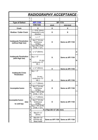
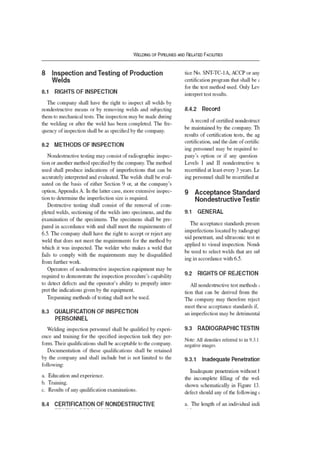
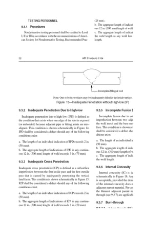
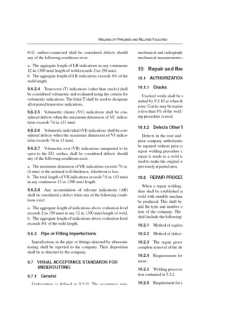
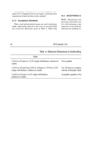
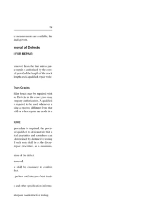
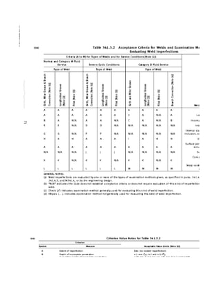
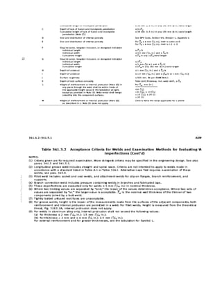
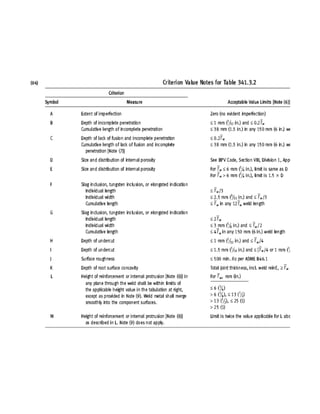
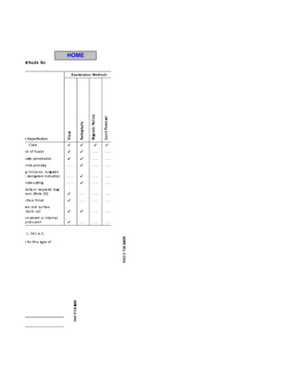
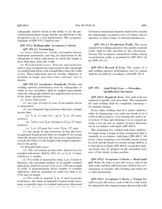
The document provides acceptance criteria for various types of defects found during radiographic testing of welds based on different codes and standards including API 1104, SP-1174, B31.3, and ASME Section IX. It lists the maximum allowable size, length, and aggregate length of defects such as cracks, incomplete penetration, incomplete fusion, burn through, slag inclusions, porosity, and undercutting.
1. The document compares acceptance criteria for radiographic testing of welds according to various industry codes and standards. It lists types of defects such as cracks, incomplete penetration, and burn through.
2. Defect sizes are evaluated based on factors like weld thickness, density compared to base metal, length, and distance between defects. Some defects are unacceptable when they exceed certain sizes.
3. Charts are provided to evaluate the acceptability of rounded indications based on weld thickness and isolation from other defects. Clustered defects have stricter criteria than random defects.
The document discusses the benefits of exercise for mental health. Regular physical activity can help reduce anxiety and depression and improve mood and cognitive functioning. Exercise has also been shown to increase gray matter volume in the brain and reduce risks for conditions like Alzheimer's and dementia.
The document is a training manual on radiographic interpretation of welds. It contains multiple radiographic images of welds with defects labeled, asking the reader to identify the defects shown. The defects illustrated include lack of root penetration, porosity, undercutting, cracking, incomplete fusion, excess penetration, spatter, slag inclusions and others. The purpose is to help trainees learn to identify various weld defects from radiographic images.
ASNT Radiographic Film Interpretation (RTFI) Notes-Dr. Samir SaadDr.Samir Saad
Ìý
The document discusses the history and impact of climate change over the past century. It notes that global temperatures and sea levels have risen significantly, with extreme weather events like hurricanes also increasing. The causes are attributed to human activities like burning fossil fuels that release greenhouse gases and trap heat in the lower atmosphere. Major impacts are expected to continue and worsen if emissions are not reduced substantially in the coming decades.
The document provides descriptions of common welding defects along with their corresponding radiographic images. It describes 14 different types of defects including misalignments, lack of penetration, inclusions, cracks, and more. Each defect entry explains what it is, such as offset or mismatch being a misalignment of pieces to be welded, and describes its radiographic image appearance, such as an abrupt change in film density across the weld image width. In total, it covers 14 common welding defects and their radiographic signatures for non-destructive testing interpretation.
This document provides definitions for various defects that may appear on radiographic images of welds, including:
- Excessive root penetration appears as a light irregular band within the weld image.
- Root concavity appears as dark areas along the weld center varying in density by imperfection depth.
- Incomplete filled groove appears as a dark area at the weld center with diffuse edges.
- Cracks appear as dark, fine lines that are usually diffuse or discontinuous.
This document discusses the selection of filler wires. It begins with an objective to learn about filler wires, ASME Section IX Table QW-422 for material grades and chemical compositions, and SFA numbers. It then introduces the differences between filler wires and electrodes, and the nomenclature used for filler wires. Examples are provided for selecting the correct filler wire based on the base metal, welding process, and referring to ASME standards. The conclusion emphasizes that filler wire selection depends on the welding process, base metal, joint type, and referencing ASME codes.
The document discusses weld defect acceptance criteria according to different codes such as ASTM B31.1, ASME VIII, ASME B31.3, and AWS D1.1. It provides details on acceptance limits for various weld defects depending on the examination method, material thickness, loading conditions, and material application. Defects discussed include cracks, lack of fusion, incomplete penetration, undercuts, porosity, and reinforcement. Acceptance criteria include maximum defect sizes, numbers of defects allowed, cumulative lengths of defects, and distances between defects.
This document provides concise summaries of key terms and concepts for a QC welding inspector interview. It defines common quality control terms like QA, QC, QAP, ITP, and explains the differences between them. It also summarizes welding concepts such as the four main welding types, the purpose of welding procedures like WPS and PQR, essential versus non-essential variables, and what organizations like ASME and AWS stand for.
This document discusses artifacts that may appear on radiographic films. It defines several types of artifacts including burned film, chemical stains, crimp marks, lead foil scratches, light leaks, pressure marks, sand/dirt marks, scratch marks, static marks, water marks, and roller marks from automatic processing. For each artifact, it provides an example radiographic image and brief description of how the artifact is caused. The purpose is to help trainees identify and understand artifacts that could affect the interpretation of radiographic images.
This document discusses phased array ultrasonic testing (PAUT) technology. It begins with an introduction to the company, Magnum, which provides both conventional x-ray and advanced technologies like PAUT. It then explains that PAUT allows the direction and focus of ultrasound beams to be changed electronically using arrays of transducer elements and delay laws. Examples are given of how PAUT can be used to detect weld flaws like porosity, slag inclusions, cracks, incomplete penetration, and incomplete fusion. The document also outlines the process for certification in phased array testing.
The document describes various visual indications that may appear on radiographic images of welds, including irregular densities, darker spots, lines, and changes in density. It also provides information on different radiographic testing methods, such as single wall single image, double wall single image, and double wall double image techniques. Acceptance criteria and standards for radiography from ASME and API are also mentioned.
This document provides alternative ultrasonic examination acceptance criteria that may be used in lieu of the criteria in ASME B31.3 when specified by the owner. The alternative criteria require automated or semi-automated ultrasonic examination using computer-based data acquisition and qualified personnel. Reflectors exceeding 20% of reference level or 4mm in length must be investigated. Flaws are evaluated based on their length, height, and aspect ratio against acceptance criteria tables that provide allowable h/t ratios. Flaws cannot exceed 4 times the weld thickness regardless of aspect ratio.
This document provides an overview of API 510 exam preparation materials covering service restrictions, joint efficiencies, and radiography requirements in ASME Section VIII. Some key points:
- Welded joints in vessels containing lethal substances must be fully radiographed and the vessel postweld heat treated if carbon/low alloy steel. Category A joints must be Type 1 (double welded) while Categories B-C can be Type 1 or 2.
- Joint categories define joint locations (e.g. longitudinal, circumferential). Type defines joint construction (e.g. double welded, single welded).
- Radiographs must show a minimum penetrameter image and identify unacceptable imperfections over certain size thresholds
Introduction to Phased Array Using the OmniScan MX2 - Part ThreeOlympus IMS
Ìý
Free webinar available: http://bit.ly/Mv7mc4
OmniScan MX2 product details: http://bit.ly/1e6mjY8
Part three of the series will cover gate and C-scan configurations for weld inspection, calibration options and limitations, and include explanation and demonstration of the OmniScan MX2 calibration wizards for manual inspection.
There will be a brief review of the previous Webinar that leads into the current topics. This will combine sector scan basics, and MX2 displays readings, and parameters in preparation for a manual sector scan weld inspection
Contact us: http://bit.ly/1rDmq94
Sign up for our Newsletter: http://bit.ly/1j5FOTy
This document provides guidelines for essential variables that determine the qualification range of a welding procedure specification in accordance with AWS D1.1 Structural Welding Code - Steel. It summarizes the qualification ranges for position, thickness/diameter, base metal selection, preheat requirements, joint details, heat input, and welding processes. The guidelines specify the testing parameters and qualified ranges for groove welds, fillet welds, plate and pipe configurations.
This document discusses various types of welding defects and imperfections including lack of fusion, porosity, slag inclusions, and solidification cracking. It describes how to identify each type, their causes, best practices for prevention, acceptance standards, and methods for detection and remediation. The key types of imperfections are classified as fabrication defects occurring during welding or service defects that form during use, and guidelines are provided for minimizing defects and producing quality welds.
API 510 Practice Exam #5 CLOSE BOOK Questions.pdfEmmanuelMatutu
Ìý
This document contains 26 multiple choice practice exam questions for API-510 certification. The questions cover topics such as materials standards, inspection procedures, corrosion rates, non-destructive testing techniques, heat treatment effects, and requirements for vessel ratings, repairs, and inspections.
API 570 provides guidance for inspecting, repairing, altering, and rerating in-service piping systems. It covers metallic and FRP piping systems used in process facilities for fluids like petroleum products, gases, and hazardous materials. The document establishes requirements for inspection plans, examining piping and components, evaluating inspection data, making repairs, and setting inspection intervals. It aims to ensure the safe operation of in-service piping by maintaining its structural integrity over time.
This document provides a summary of welding procedure specifications (WPS). It lists 69 WPS entries that include the process, filler metal, base metal, thickness range, diameter range, and post weld heat treatment requirements. The WPS cover a variety of welding processes including shielded metal arc welding, gas tungsten arc welding, flux cored arc welding, and submerged arc welding. The WPS specify the materials, thicknesses, diameters, and heat treatments for welding different material grades.
This document provides the 2021 edition of the ASME Boiler and Pressure Vessel Code Section V, which contains requirements and guidelines for nondestructive examination methods. It defines terms related to nondestructive examination and outlines qualification requirements for personnel. The document establishes general requirements for equipment, procedures, calibration, examinations, evaluations, and documentation for various nondestructive examination methods like radiography, ultrasonics, and real-time radioscopy. Appendices provide additional details for specific nondestructive examination methods and exceptions to other industry standards.
The document discusses the basics of ultrasonic testing including:
- A 9.5 day course to train participants in ultrasonic testing and prepare them for examinations.
- Common NDT methods and that the best method depends on various factors and conditions.
- Basic principles of ultrasonic testing including transmitting sound through materials to detect defects based on differences in signal return times.
- Key concepts in ultrasonic testing like frequency, wavelength, velocity and their relationships.
This document provides an overview of radiographic interpretation for periapical and panoramic dental x-rays. It defines dental radiography and describes the main intraoral and extraoral views. Periapical radiographs show the entire tooth and surrounding structures, and are useful for detecting dental issues like caries, periapical pathology, implants and more. Panoramic radiographs provide a wide view of the jaws and are used to assess issues like gross caries, fractures, cysts and tumors. The document outlines the normal radiographic anatomy seen in these views and provides guidance on interpreting radiographs through steps like localization, observation, interpretation and correlation to arrive at a diagnosis.
The passage discusses the importance of summarization for processing large amounts of text data. It notes that automatic summarization systems aim to condense long documents into shorter summaries while maintaining the most important concepts and entities. The challenges of building such systems include identifying the most salient pieces of information, understanding natural language at a deeper level, and generating coherent summaries.
This document provides a reference guide for radiographers to interpret welds. It contains descriptions and examples of various types of discontinuities that can be detected in radiographic images of welds, including mismatches, lack of penetration, inclusions, cracks, porosity, and other defects. The guide defines each discontinuity type and provides details on their visual appearance on radiographs to aid in identification.
The document discusses the user story lifecycle including conducting an inception, identifying roles and personas, eliciting business processes, generating user stories, arranging stories into releases and iterations, and providing details for developers using techniques like happy path, sad path, being SMART, and Given, When, Then. It emphasizes that developers need details to implement stories effectively.
The discovery of X-rays and the phenomenon of radioactivity and their application to the examination of objects provided the starting point for the advancement of industrial radiography. This technique is one of the most widely used for the detection of internal defects such as voids and porosity. Planar defects can also be detected by radiography with some proper orientation. Radiography is also suitable for detecting changes in material composition, thickness measurements and locating unwanted or defective components hidden from view in an assembled part.
Nlng pipeline acceptance criteria per api std 1104, page 1Luis Luis
Ìý
The document outlines acceptance criteria for various defects that may be found during non-destructive testing of welds for an NLNG pipeline. Key criteria include:
- Incomplete fusion indications must be less than 2 inches individually or in aggregate in any 12 inches of weld.
- Internal concavities must be less than 1/4 inches if the density exceeds the base metal, and less than 1/2 inches in aggregate in any 12 inches.
- Elongated slag inclusions must be less than 2 inches individually and in aggregate in any 12 inches.
- Isolated slag inclusions and porosity indications cannot exceed specified sizes and must be sufficiently separated.
- Cracks and burn
This document provides standards for reference radiographs used to evaluate steel castings up to 2 inches thick. It includes:
1. An overview of the scope and purpose of the reference radiographs, which illustrate various types and severity levels of discontinuities commonly found in steel castings.
2. Descriptions of the categories and types of discontinuities represented, including gas porosity, inclusions, shrinkage, cracks, tears, and mottling. The discontinuities are graded on a scale of 1 to 5 based on their quantity, size, and distribution.
3. Procedures for how to use the reference radiographs to evaluate production radiographs and determine whether castings meet specified radi
The document discusses the basic principles of ultrasonic testing. It explains oscillation and wave propagation, how ultrasound is generated and received using the piezoelectric effect, and how it is used to inspect materials and detect flaws. Diagrams illustrate longitudinal and transverse wave propagation, reflection, refraction, and techniques for through-transmission, plate, and weld testing.
Radiographic techniques are used to inspect castings and welds for defects. Common casting defects appear on radiographs as gas porosity, sand inclusions, shrinkage cavities, core shifts, metallic inclusions, cracks, and cold shuts. Weld defects include lack of penetration, incomplete fusion, slag inclusions, porosity, and undercut. Proper film processing, viewing conditions, and knowledge of defect appearances are required to accurately interpret radiographs and evaluate component quality.
Weld Defects and Material Properties - PresentationBrett Leary
Ìý
This document discusses weld defects, specifically porosity in welds. It defines porosity as gas holes or voids found within a weld caused when gases trapped in the weld do not escape as it solidifies. The document outlines the main causes of porosity as dirt and moisture, describes the detrimental effects on strength and fatigue life, and provides methods for preventing and detecting porosity, including maintaining cleanliness and using non-destructive testing techniques.
The document summarizes ASME Section VIII Division 1 code requirements for material identification, repair of material defects, Charpy impact testing of production test coupons, weld joint categories, radiographic and ultrasonic examination, welding requirements, and acceptance standards for non-destructive examination. Key points include requirements for original material markings, testing procedures that vary based on joint category and position, examination types based on joint size and material thickness, welder identification, pre-welding surface preparation, and imperfection acceptance criteria.
This document discusses weldability and defects in weldments. It covers various topics related to weld design, residual stresses, weld defects, and the weldability of different materials such as steels, aluminum alloys, copper alloys, titanium alloys, and magnesium alloys. The objectives are for students to understand causes of residual stresses and distortions, differentiate between weld defects, and suggest remedies. Weldability depends on factors like material composition and welding techniques. Some materials like steel are more weldable than others such as aluminum.
1) Ultrasonic testing techniques include pulse echo, through transmission, and transmission with reflection. Pulse echo uses a single probe to send and receive sound to detect defect depth and orientation. Through transmission uses probes on opposite sides to detect defects but not location. Transmission with reflection can locate defects.
2) The sound beam has a near zone where intensity varies and a far zone with exponential decay. The near zone length depends on probe frequency and diameter, with higher frequency and larger diameter increasing length.
3) Beam spread is smaller with higher frequency and larger diameter probes. Compression waves have a smaller beam spread than shear waves. Snell's law and critical angles determine how sound refracts between materials
Non-Destructive Testing (NDT) - Industrial Radiography Normal Working Proceduresshahar_sayuti
Ìý
The document discusses safety and security in industrial radiography. It describes the basic principles and applications of radiography techniques using radiation sources like x-rays and gamma rays. It also discusses the equipment used including radiation devices, safety equipment, and procedures to control external radiation exposure through principles of time, distance and shielding.
The document discusses the results of a study on the impact of COVID-19 lockdowns on air pollution. Researchers analyzed data from dozens of countries and found that lockdowns led to an average decline of nearly 30% in nitrogen dioxide levels over cities. However, they also observed that this improvement was temporary and air pollution rebounded once lockdown restrictions began lifting. Overall, the study highlights how human activities are a major driver of air pollution but also that systemic changes are needed for long-term air quality improvements.
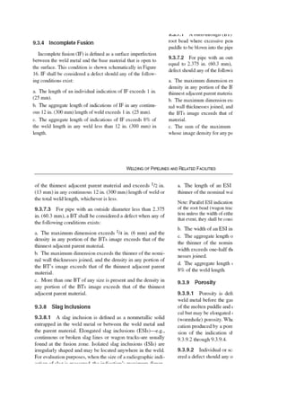
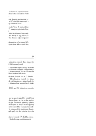
1. RADIOGRAPHY ACCEPTANCE CRITERIA
Prepared by: Mathew.N.Samuel- OSE311M (Marmul)
Type of Defect API 1104 SP-1174 B31.3 (Normal)
Clik link SOUR NON SOUR Clik link
Crack X X X
L > 5/32' (4mm)
Shallow / Catter Crack measured in any X X
direction
a- L > 1"
Ag.L1" (In any
Inadequate Penetration b
continuous X Same as API 1104
(without High low) -
12"WL)
Ag.L>8% of WL
c-
(if WL < 12")
a- L> 2" (50mm) a-
Inadequate Penetration Ag.L > 3" X Same as API 1104
(with High low)
b
(in any b-
-
continuous 12"
WL )
a- L> 2" (50mm)
X Same as API 1104
Ag.L > 2"
Inadequate Cross
Penetration b
- (in any
continuous 12"
WL ) X Same as API 1104
a- L > 1" (25mm)
Ag.L1" (In any
b
Incomplete fusion continuous X Same as API 1104
-
12"WL)
Ag.L > 8% of WL
c-
(if WL < 12")
a- L > 1" (25mm)
Incomplete fusion Ag.L1" (In any
b
(due continuous X Same as API 1104
-
to cold lap) 12"WL)
Ag.L > 8% of WL
c-
(if WL < 12")
1 For Pipe OD >2" (60.3mm)
1 Max Ø >¼"
a- (6mm)
1 Max Ø> t of
b thinnest adj. Same as API 1104 Same as API 1104
- Base metal
Burn Through (BT)
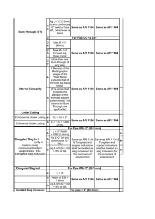
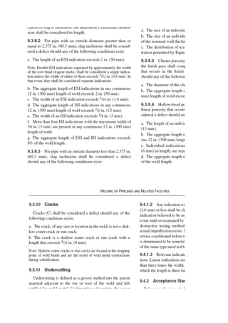
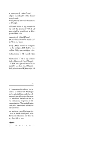
2. Ag L> ½" (13mm)
in any continuous
1
12" weld or total Same as API 1104 Same as API 1104
c-
WL (whichever is
Burn Through (BT) less)
2 For Pipe OD <2 3/8"
2 Max Ø >¼"
a- (6mm)
2 Max Ø> t of
b thinnest adj. Same as API 1104 Same as API 1104
- Base metal
More than one
2
Burn through of
c-
any size
If Density of the
Radiographic
Image of the
a- Weld Metal
exceeds that of
thinnest adj.Base
Metal
Internal Concavity (The areas that Same as API 1104 Same as API 1104
exceeds the
Density of the
b thinnest adjcent
- parent metal,The
criteria for Burn
Through are
applicable)
Under Cutting
EU-External Under cutting a- EU + IU > 2"
Same as API 1104 Same as API 1104
b EU + IU > 1/6th
IU-Internal Under cutting
- of WL
For Pipe OD> 2" (60.3 mm)
L > 2" Width
a- a-
>1/16" (1.6mm)
Ag.L>2" (in any
Elongated Slag Incl b
continuous 12" Same as API 1104 Same as API 1104 & b-
(only in - & Tungsten and Tungsten and
WL)
fussion zone) copper inclusiions copper inclusiions
continuous/brocken/ Ag.L of ESI + ISI shall be treated as shall be treated as
c- c-
wagontracks - ESI- > 8% of WL slag inclussion for slag inclussion for
Elongated Slag Inclussion the purposes of the purposes of
assessment assessment
Elongated Slag Incl For Pipe OD< 2" (60.3 mm)
a- L > 3t
b
Width of ESI >
Same as API 1104 Same as API 1104
- 1.6mm
Ag.L of ESI + ISI
c-
> 8% of WL
Isolated Slag Inclusion For pipe > 2" (60.3mm)
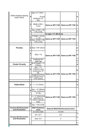
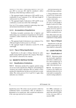
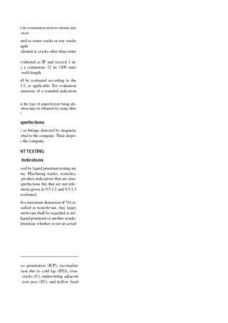
3. Ag.L>½" 13mm
(Other locations leaving
a- (in any a-
fusion Zone)
continous 12"
WL)
b Width of ISI >
Same as API 1104 Same as API 1104 b-
- 3.mm
Ag.L of ESI + ISI
c- c-
> 8% of WL
For pipe < 2" (60.3mm)
If Width > 0.5t &
a-
L > 2t
Same as API 1104 Same as API 1104
b Ag.L of ESI + ISI
- > 8% of WL
Porosity a- Size >1/8" (3mm) a-
b
Size > ¼t b-
- Same as API 1104 Same as API 1104
Scattered Por
c- c-
(refer fig)
Ø of Cluster > ½"
Cluster Porosity a- a-
(13mm)
Ag.L > ½"
b (13mm) in any
b-
- continuous 12"
WL
Same as API 1104 Same as API 1104
Single Ø of Pore
c- in Cluster Pore >
1/16" (2mm)
Hollow Bead a- L > ½ (13mm) a-
Ag.L > 2" (50mm)
b
in any continuous
-
12" WL
L > ¼" (6mm) but
Same as API 1104 Same as API 1104
separated by
c-
<50mm between
them
d
Ag.L > 8% of WL
-
Excess Reinforcement Wall Thickness
External Weld Reinforcement (mm) Wall Thickness
and Penetration (mm)
6.4 and under 1.6 mm ≤ 6 mm (1/4")
> 6 mm (1/4"),≤ 13 mm
6.4 -12.7 2.5
Excess Reinforcement
> 13 mm (1/2"), 25 mm
and Penetration Over 12.7 3
> 25 mm (1")
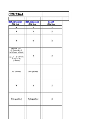
4. ANCE CRITERIA
B31.3 (Normal) B31.3 (Severe) Sec IX
Clik link Clik link Clik link
X X X
X X X
X X X
Depth > 1/32 "
(0.78mm) & 0.2t
(whichever is Less)
X X
Ag.L > 1.5" (38mm)
in any 6" WL
(150mm)
Not specified Not specified
X X X
Not specified Not specified X
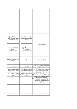
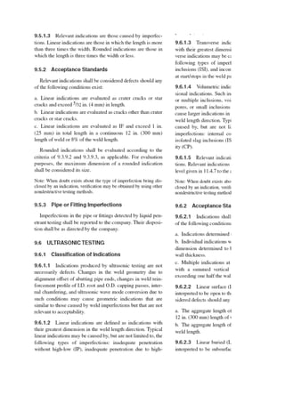
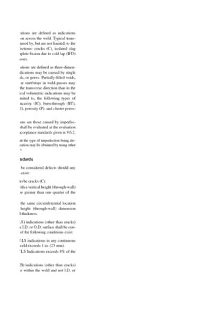
5. Wj shall never be Wj shall never be
less than the base less than the base
metal thickness metal
Not specified
Wj = Total Joint Wj = Total Joint
Thick + Thick +
reinforcement reinforcement
Depth > 1/32" (1mm)
X Not specified
& ≤ t/4
L > 1/8" (3 mm) t upto 3/8"
L > 2t a- L > t/3 a-
(10 mm)
W > 3.125mm & t/2 W > 2.34mm & t/3 L=1/3 t for t > 3/8" (10 mm)
b- b-
(whichever is less) (whichever is less) upto 57 mm Inclusive
L = 3/4" (19 mm)
Ag.L > 4t in any 6" Ag.L > 4t in any 6"
c- c- for t > 57
WL WL
Ag.L > t in mm
a length of 12t
& distance between
d-
indication exceeds 6L
where "L" is the longest
indication
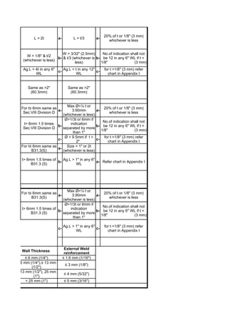
6. 20% of t or 1/8" (3 mm)
L > 2t a- L > t/3 a-
whichever is less
W > 3/32" (2.5mm) No.of indication shall not
W > 1/8" & t/2
b- & t/3 (whichever is b- be 12 in any 6" WL if t <
(whichever is less)
less) 1/8" (3 mm)
Ag.L > 4t in any 6" Ag.L < t in any 12" for t >1/8" (3 mm) refer
c- c-
WL WL chart in Appendix I
Same as >2" Same as >2"
(60.3mm) (60.3mm)
Max Ø>¼ t or
For t≤ 6mm same as 20% of t or 1/8" (3 mm)
a- 3.90mm a-
Sec.VIII Division D whichever is less
(whichever is less)
Ø>1/3t or 6mm if
No.of indication shall not
t> 6mm 1.5 times indication
b- b- be 12 in any 6" WL if t <
Sec.VIII Division D separated by more
1/8" (3 mm)
than 1"
Ø > 9.5mm if t > for t >1/8" (3 mm) refer
c- c-
2" chart in Appendix I
For t≤ 6mm same as Size > 1" or 2t
a-
B31.3(S) (whichever is less)
t> 6mm 1.5 times of Ag.L > 1" in any 6"
b- a- Refer chart in Appendix I
B31.3 (S) WL
Max Ø>¼ t or
For t≤ 6mm same as 20% of t or 1/8" (3 mm)
a- 3.90mm a-
B31.3(S) whichever is less
(whichever is less)
Ø>1/3t or 6mm if
No.of indication shall not
t> 6mm 1.5 times of indication
b- b- be 12 in any 6" WL if t <
B31.3 (S) separated by more
1/8" (3 mm)
than 1"
Ag.L > 1" in any 6" for t >1/8" (3 mm) refer
c- c-
WL chart in Appendix I
External Weld
Wall Thickness
reinforcement
≤ 6 mm (1/4") ≤ 1.6 mm (1/16")
> 6 mm (1/4"),≤ 13 mm
≤ 3 mm (1/8")
(1/2")
> 13 mm (1/2"), 25 mm
≤ 4 mm (5/32")
(1")
> 25 mm (1") ≤ 5 mm (3/16")