Salient featurs of 80386
- 1. Agenda: Friday, August 22, 2014 Architecture of 80386 ÔÉòSalient Features of 80386 ÔÉòFunctional Block Diagram of 80836 ÔÉòPin Description of 8086 1
- 2. Salient Features of 80386X It supports 8/16/32 bit data operands It has 132 pins. It has 32-bit internal registers It supports 32-bit data bus and 32-bit non-multiplexed address bus Friday, August 22, 2014 2Architecture of 80386
- 3. Cont’d… It supports Physical Address of 4GB Maximum Segment size of 4GB Virtual Address of 64TB(4GB seg. * 16,384 segments) 3 Types of 80386 1. 80386DX(floating point capability.) 2. 80386SX(16-bit data bus) 3. 80386SL(several power management options) Friday, August 22, 2014 3Architecture of 80386
- 4. Cont’d… It operates in 3 different modes Real Protected Virtual . MMU provides virtual memory, paging and 4 levels of protection Low cost & low power consumption. Clock Frequency : 20,25 and 33MHz Friday, August 22, 2014 4Architecture of 80386
- 5. Friday, August 22, 2014 Architecture of 80386 5 **Snapshot of 80386
- 6. Friday, August 22, 2014 6Architecture of 80386 Central Processing Unit Bus Control UnitMemory Management Unit
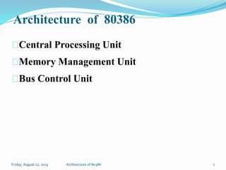
- 7. Architecture of 80386 Central Processing Unit Memory Management Unit Bus Control Unit Friday, August 22, 2014 7Architecture of 80386
- 8. Central Processing Unit Execution Unit: Execution unit has 8 General and Special purpose registers, which are either used for handling data or calculating offset addresses. The 64-bit barrel shifter increases the speed of all shift, rotate. Multiply/divide logic implements the bit-shift- rotate algorithms to complete the operation in minimum time. 8Friday, August 22, 2014 Architecture of 80386 The CPU is further divided into: Execution Unit Instruction Unit
- 9. Instruction Unit: It decodes the opcode bytes received from the 16-byte instruction code queue and arrange them into a 3- decoded instruction queue. After decoding it is passed to control section for deriving necessary control signals 9Friday, August 22, 2014 Architecture of 80386
- 10. Memory Management Unit MMU consists of a segmentation unit and paging unit. Segmentation Unit: Uses of two address components - segment and offset – for relocability and sharing of data. It allows a maximum segment size of 4GB. 10Friday, August 22, 2014 Architecture of 80386
- 11. Memory Management Unit Paging Unit It organizes physical memory in terms of pages of 4KB size. It works under the control of segmentation unit i.e. each segment is divided into pages. It converts linear addresses into physical addresses. The control and attribute PLA checks privileges at page level. 11Friday, August 22, 2014 Architecture of 80386
- 12. Bus Control Unit 12 It has a prioritizer to resolve the priority of various bus requests. This controls the access of the bus. The address driver drives the bus enable and address signals A2 – A31. Friday, August 22, 2014 Architecture of 80386
- 13. Friday, August 22, 2014 Architecture of 80386 13 **Snapshot of 80386
- 14. Pin Layout Friday, August 22, 2014 14 Architecture of 80386
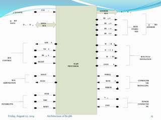
- 15. 80386 PROCESSOR CLK 2 2 X CLOCK DATA BUS D 0 – D 31 32 BIT DATA BUS CONTROL ADS # NA # BS 16 # READY HOLD HLDA INTR NMI RESET BUS ARBITRATION INTERRUPTS GND V CC POWER CONNECTIO NS ERROR # BUSY # PEREQ LOCK # M / IO D / C # ADDRESS BUS A 2 – A 31 BE 3 # BE 2 # BE 1 # BE 0 # W / R # COPROCESS OR SIGNALLING BUS CYCLE DEFINATION BYTE ENABLI NES 32 – BIT ADDRESS Friday, August 22, 2014 15Architecture of 80386
- 16. W/R: The write / read output distinguishes the write and read cycles from one another. D/C: Whether the bus operation is data R/W or control word transfer. M/IO: Operation is memory or I/O. PEREQ: Requset to fetch first part of data word for coprocessor. BUSY: Coprocessor uses this to notify that, instruction execution is going on. LOCK: The LOCK output pin enables the CPU to prevent the other bus masters from gaining the control of the system bus. NA: The next address input pin, if activated, allows address pipelining. Friday, August 22, 2014 16Architecture of 80386
- 17. ADS#: The address status output pin indicates that the address bus and bus cycle definition pins( W/R#, D/C#, M/IO#, BE0# to BE3# ) are carrying the respective valid signals. BS16: The bus size – 16 input pin allows the interfacing of 16 bit devices with the 32 bit wide 80386 data bus. READY#: The ready signals indicates to the CPU that the previous bus cycle has been terminated and the bus is ready for the next cycle. VCC: These are system power supply lines. VSS/GND:These return lines for the power supply. Friday, August 22, 2014 17Architecture of 80386
- 18. Friday, August 22, 2014 18Architecture of 80386 S.N. Parameter 8086 80386 1 Number of Pins 40 132 2 Pin Nature DIP No DIP 3 Clock rate Supports 5,8 & 10Mhz 16 & 20 MHz 4 Operating Mode 2(viz. minimum & Maximum) 3(viz. real, protected & virtual) 5 Signal Category 3 2 6 Number of Registers 14, 16bit 16, 32 bit 7 Architecture(Processor) 16bit 32bit 8 Architecture Composition in unit 2 (viz. EU, BIU) 3(CPU,MMU & BCU) 9 Data Bus 16 bit 32 bit 10 Address Bus 20 bit 32 bit 11 Memory Access Up to 1 MB Up to 4 Gb 12 Power Consumption High Low 13 Cost High Low


