satellite design requirements
0 likes469 views

The document provides satellite design requirements for compatibility with the LM-3A series launch vehicles, including: - Structural frequency and load requirements to avoid dynamic coupling with the launch vehicle. Maximum load factors during different flight conditions are provided. - Requirements for coupled load analysis to predict dynamic response and ensure adequate safety margins. - Safety requirements and procedures that must be followed during launch operations. - Constraints on satellite mass and center of gravity placement. - Vibration, acoustic, shock, and static load test specifications for satellite qualification and acceptance testing.
satellite design requirements
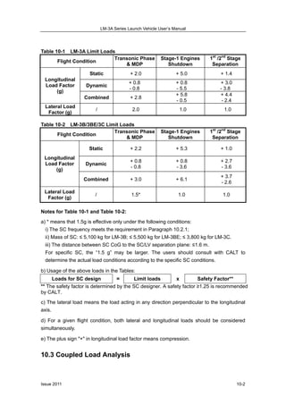
- 1. LM-3A Series Launch Vehicle UserŌĆÖs Manual Issue 201110-1 CHAPTER 10 SATELLITE DESIGN REQUIREMENTS 10.1 Introduction This Chapter introduces the satellite design requirements from the launch vehicle compatibility perspective, which include load conditions, coupled load analysis, safety requirements, satellite mass and CoG, specifications of satellite qualification and acceptance tests. 10.2 Load Conditions for Satellite Design 10.2.1 Frequency Requirement To avoid the SC dynamic coupling with the launch vehicle, the primary frequency of SC structure should meet the following requirement (under the condition that SC/LV separation plane is considered as a rigid body): The first order lateral frequency of the main mode: > 10 Hz The first order longitudinal frequency of the main mode: > 30 Hz 10.2.2 Loads Applied for SC Structure Design The maximum lateral load occurs when the launch vehicle flies with a transonic speed or under Maximum Dynamic Pressure (MDP). The maximum longitudinal static load occurs at the first stage engines shutdown for LM-3A. The maximum longitudinal static load occurs at the boostersŌĆÖ engines shutdown for LM-3B, LM-3BE and LM-3C. The maximum longitudinal dynamic load occurs immediately following the first and second stage separation. Therefore, the following limit loads corresponding to different flight conditions are recommended for SC design consideration. See Table 10-1 and Table 10-2.
- 2. LM-3A Series Launch Vehicle UserŌĆÖs Manual Issue 2011 10-2 Table 10-1 LM-3A Limit Loads Flight Condition Transonic Phase & MDP Stage-1 Engines Shutdown 1st /2nd Stage Separation Static + 2.0 + 5.0 + 1.4 Dynamic + 0.8 - 0.8 + 0.8 - 5.5 + 3.0 - 3.8 Longitudinal Load Factor (g) Combined + 2.8 + 5.8 - 0.5 + 4.4 - 2.4 Lateral Load Factor (g) / 2.0 1.0 1.0 Table 10-2 LM-3B/3BE/3C Limit Loads Flight Condition Transonic Phase & MDP Stage-1 Engines Shutdown 1st /2nd Stage Separation Static + 2.2 + 5.3 + 1.0 Dynamic + 0.8 - 0.8 + 0.8 - 3.6 + 2.7 - 3.6 Longitudinal Load Factor (g) Combined + 3.0 + 6.1 + 3.7 - 2.6 Lateral Load Factor (g) / 1.5* 1.0 1.0 Notes for Table 10-1 and Table 10-2: a) * means that 1.5g is effective only under the following conditions: i) The SC frequency meets the requirement in Paragraph 10.2.1; ii) Mass of SC: Ōēż 5,100 kg for LM-3B; Ōēż 5,500 kg for LM-3BE; Ōēż 3,800 kg for LM-3C. iii) The distance between SC CoG to the SC/LV separation plane: Ōēż1.6 m. For specific SC, the ŌĆ£1.5 gŌĆØ may be larger. The users should consult with CALT to determine the actual load conditions according to the specific SC conditions. b) Usage of the above loads in the Tables: Loads for SC design = Limit loads x Safety Factor** ** The safety factor is determined by the SC designer. A safety factor Ōēź1.25 is recommended by CALT. c) The lateral load means the load acting in any direction perpendicular to the longitudinal axis. d) For a given flight condition, both lateral and longitudinal loads should be considered simultaneously. e) The plus sign "+" in longitudinal load factor means compression. 10.3 Coupled Load Analysis
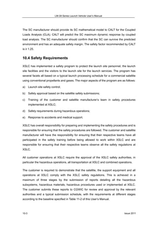
- 3. LM-3A Series Launch Vehicle UserŌĆÖs Manual Issue 201110-3 The SC manufacturer should provide its SC mathematical model to CALT for the Coupled Loads Analysis (CLA). CALT will predict the SC maximum dynamic response by coupled load analysis. The SC manufacturer should confirm that the SC can survive the predicted environment and has an adequate safety margin. The safety factor recommended by CALT is Ōēź 1.25. 10.4 Safety Requirements XSLC has implemented a safety program to protect the launch site personnel, the launch site facilities and the visitors to the launch site for the launch services. The program has several facets all based on a typical launch processing schedule for a commercial satellite using conventional propellants and gases. The major aspects of the program are as follows: a) Launch site safety control; b) Safety approval based on the satellite safety submissions; c) Training of the customer and satellite manufacturerŌĆÖs team in safety procedures implemented at XSLC; d) Safety requirements during hazardous operations; e) Response to accidents and medical support. XSLC has overall responsibility for preparing and implementing the safety procedures and is responsible for ensuring that the safety procedures are followed. The customer and satellite manufacturer will have the responsibility for ensuring that their respective teams have all participated in the safety training before being allowed to work within XSLC and are responsible for ensuring that their respective teams observe all the safety regulations at XSLC. All customer operations at XSLC require the approval of the XSLC safety authorities, in particular the hazardous operations, all transportation at XSLC and combined operations. The customer is required to demonstrate that the satellite, the support equipment and all operations at XSLC comply with the XSLC safety regulations. This is achieved in a maximum of three stages by the submission of reports detailing all the hazardous subsystems, hazardous materials, hazardous procedures used or implemented at XSLC. The customer submits these reports to CGWIC for review and approval by the relevant authorities and a typical submission schedule, with the requirements at different stages according to the baseline specified in Table 11-2 of this UserŌĆÖs Manual.
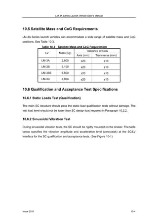
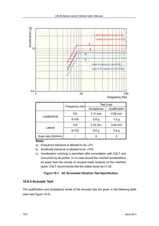
- 4. LM-3A Series Launch Vehicle UserŌĆÖs Manual Issue 2011 10-4 10.5 Satellite Mass and CoG Requirements LM-3A Series launch vehicles can accommodate a wide range of satellite mass and CoG positions. See Table 10-3. Table 10-3 Satellite Mass and CoG Requirement Tolerance of CoG LV Mass (kg) Axis (mm) Transverse (mm) LM-3A 2,600 ┬▒20 ┬▒10 LM-3B 5,100 ┬▒20 ┬▒10 LM-3BE 5,500 ┬▒20 ┬▒10 LM-3C 3,800 ┬▒20 ┬▒10 10.6 Qualification and Acceptance Test Specifications 10.6.1 Static Loads Test (Qualification) The main SC structure should pass the static load qualification tests without damage. The test load level should not be lower than SC design load required in Paragraph 10.2.2. 10.6.2 Sinusoidal Vibration Test During sinusoidal vibration tests, the SC should be rigidly mounted on the shaker. The table below specifies the vibration amplitude and acceleration level (zero-peak) at the SC/LV interface for the SC qualification and acceptance tests. (See Figure 10-1)
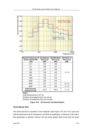
- 5. LM-3A Series Launch Vehicle UserŌĆÖs Manual Issue 201110-5 Test Load Frequency (Hz) Acceptance Qualification 5-8 3.11 mm 4.66 mm Longitudinal 8-100 0.8 g 1.2 g 5-8 2.33 mm 3.50 mm Lateral 8-100 0.6 g 0.9 g Scan rate (Oct/min) / 4 2 Notes: a) Frequency tolerance is allowed to be ’é▒2% b) Amplitude tolerance is allowed to be ’é▒10% c) Acceleration notching is permitted after consultation with CALT and concurred by all parties. In no case should the notched accelerations be lower than the results of coupled loads analysis on the interface plane. CALT recommends that the safety factor be Ōēź1.25. Figure 10-1 SC Sinusoidal Vibration Test Specification 10.6.3 Acoustic Test The qualification and acceptance levels of the acoustic test are given in the following table (also see Figure 10-2).
- 6. LM-3A Series Launch Vehicle UserŌĆÖs Manual Issue 2011 10-6 Central Frequency of Octave Bandwidth (Hz) Acceptance Test Level (dB) Qualification Test Level (dB) Deviation of Test Level (dB) 31.5 124 128 63 129 133 125 134 138 250 138 142 500 133 137 1000 129 133 2000 128 132 -2 / +4 4000 127 131 -5 / +4 8000 122 126 -5 / +5 Total Acoustic Pressure Level 141.5 145.5 -1 / +3 Notes: 0 dB referenced to 2├Ś10-5 Pa. Duration of acceptance test: one minute. Duration of qualification test: two minutes. Figure 10-2 SC Acoustic Test Specification 10.6.4 Shock Test The shock test level is specified in this Paragraph (See Figure 10-3 and 10-4). Such test shall be performed once for acceptance, and twice for qualification. A tolerance of ┬▒6.0 dB in test specification is allowed, however, the test levels applied shall ensure that the shock
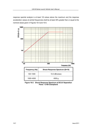
- 7. LM-3A Series Launch Vehicle UserŌĆÖs Manual Issue 201110-7 response spectral analysis is at least 1/6 octave above the maximum and the response acceleration values at central frequencies shall be at least 30% greater than or equal to the nominal values given in Figures 10-3 and 10-4. Frequency (Hz) Shock Response Spectrum (Q=10) 100~1000 10.5 dB/octave 1000~4000 4000 g Figure 10-3 Shock Response Spectrum at SC/LV Separation Plane - C100 Clampband
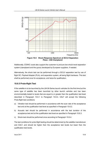
- 8. LM-3A Series Launch Vehicle UserŌĆÖs Manual Issue 2011 10-8 Figure 10-4 Shock Response Spectrum at SC/LV Separation Plane - C60 Clampband Additionally, CGWIC could also support the customer to procure low shock level separation system (clampband and the pyros) developed by European suppliers, if needed. Alternatively, the shock test can be performed through a SC/LV separation test by use of flight SC, Payload Adapter (PLA), and separation system, all being flight hardware. This test shall be performed once for acceptance, and twice for qualification. 10.6.5 Proto-flight Test If the satellite is to be launched by the LM-3A Series launch vehicles for the first time but the same type of satellite has been launched by other launch vehicles and has been environmentally tested to levels that are equal to or greater than the qualification test level described in Paragraph 10.6.1 to Paragraph 10.6.4, CALT will accept the following Proto-flight test conditions: a) Vibration test should be performed in accordance with the scan rate of the acceptance test and at the qualification test level as specified in Paragraph 10.6.2. b) Acoustic test should be performed in accordance with the test duration of the acceptance test and at the qualification test level as specified in Paragraph 10.6.3. c) Shock test should be performed once according to Paragraph 10.6.4. The test conditions for proto-flight testing should be determined by the satellite manufacturer and CALT, and should be higher than the acceptance test levels but lower than the qualification test levels.