際際滷

際際滷Share a Scribd company logo
Scissor Jack- Structural
Analysis
By- Manish Meena(2014102)
Prashant Singh(2014126)
Subhadeepta Sahoo(2014183)
Introduction
 A scissor jack is operated simply by turning a small crank that is inserted
into one end of the scissor jack.
 The end fits into a ring hole mounted on the end of the screw, which is
the object of force on the scissor jack. When this crank is turned, the
screw turns, and this raises the jack.
 The screw acts like a gear mechanism. It has teeth (the screw thread),
which turn and move the two arms, producing work. Just by turning this
screw thread, the scissor jack can lift a vehicle that is several thousand
pounds.
Construction
 A scissor jack has four main pieces of metal and two base ends. The four metal
pieces are all connected at the corners with a bolt that allows the corners to
swivel.
 A screw thread runs across this assembly and through the corners. As the screw
thread is turned, the jack arms travel across it and collapse or come together,
forming a straight line when closed. Then, moving back the other way, they raise
and come together.
 When opened, the four metal arms contract together, coming together at the
middle, raising the jack. When closed, the arms spread back apart and the jack
closes or flattens out again.
Courtesy: Google
Force and Stress Analysis
of Screw Jack assembly
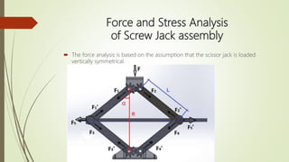
 The force analysis is based on the assumption that the scissor jack is loaded
vertically symmetrical.
 The maximum capacity for the scissor jack is 600 kg.
 Maximum Load = 600kg * 9.81 m/s^2 = 5886 N
 L= 145 mm, the length of the arms
e =180 mm, the length from base to top center of holes (At Minimum raising
height of the jack)
=> The angle is decreasing at maximum raising height of the jack.
Consequently, the maximum force is decreased.
=> Since the maximum loading force will act at the minimum raising height of the jack,
the design stresses will be analyzed at that point.
Scissor Jack- FEM Structural and Fatigue Analysis
Material Used- Structural Steel
Design and Analysis of Individual Parts
Moment= 5.64N-m
Fixed Support
Power Screw
Maximum Displacement
Maximum Stress
Top Plate
Force= 5886N
Fixed Holes
Maximum Displacement
Maximum Stress
Fixed Support
Force=4738N
Base plate
Maximum Displacement
Maximum Stress
Fixed holes
Force=4738N
Connecting Arm
Maximum Displacement
Maximum Stress
Force=5886N
Fixed Support
Scissor Jack- FEM Structural and Fatigue Analysis
Results
 On doing fatigue analysis, we found that the life of the assembly is 860 days on a
fully reversed load condition.
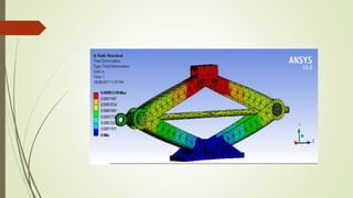
 The maximum displacement was found in the top bracket and maximum stress in
the pin holes.
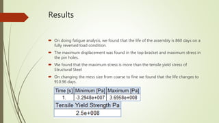
 We found that the maximum stress is more than the tensile yield stress of
Structural Steel
 On changing the mess size from coarse to fine we found that the life changes to
910.96 days.

More Related Content

Scissor Jack- FEM Structural and Fatigue Analysis

  • 1. Scissor Jack- Structural Analysis By- Manish Meena(2014102) Prashant Singh(2014126) Subhadeepta Sahoo(2014183)
  • 2. Introduction A scissor jack is operated simply by turning a small crank that is inserted into one end of the scissor jack. The end fits into a ring hole mounted on the end of the screw, which is the object of force on the scissor jack. When this crank is turned, the screw turns, and this raises the jack. The screw acts like a gear mechanism. It has teeth (the screw thread), which turn and move the two arms, producing work. Just by turning this screw thread, the scissor jack can lift a vehicle that is several thousand pounds.
  • 3. Construction A scissor jack has four main pieces of metal and two base ends. The four metal pieces are all connected at the corners with a bolt that allows the corners to swivel. A screw thread runs across this assembly and through the corners. As the screw thread is turned, the jack arms travel across it and collapse or come together, forming a straight line when closed. Then, moving back the other way, they raise and come together. When opened, the four metal arms contract together, coming together at the middle, raising the jack. When closed, the arms spread back apart and the jack closes or flattens out again.
  • 5. Force and Stress Analysis of Screw Jack assembly The force analysis is based on the assumption that the scissor jack is loaded vertically symmetrical.
  • 6. The maximum capacity for the scissor jack is 600 kg. Maximum Load = 600kg * 9.81 m/s^2 = 5886 N L= 145 mm, the length of the arms e =180 mm, the length from base to top center of holes (At Minimum raising height of the jack)
  • 7. => The angle is decreasing at maximum raising height of the jack. Consequently, the maximum force is decreased. => Since the maximum loading force will act at the minimum raising height of the jack, the design stresses will be analyzed at that point.
  • 9. Material Used- Structural Steel Design and Analysis of Individual Parts
  • 22. Results On doing fatigue analysis, we found that the life of the assembly is 860 days on a fully reversed load condition. The maximum displacement was found in the top bracket and maximum stress in the pin holes. We found that the maximum stress is more than the tensile yield stress of Structural Steel On changing the mess size from coarse to fine we found that the life changes to 910.96 days.