Shakerpresentation
- 1. Vibration Test Platform Northern Illinois University Department of Engineering and Engineering Technology Anthony Smith Denis Vasilescu
- 2. Overview ? What is the problem weí»re addressing? ? What solutions already exist? ? What are we doing different? ? Whatí»s the marketability of our design? ? What have we accomplished so far?
- 3. What's the problem at hand? ? Vibrations are everywhere, and can create effects ranging from discomfort to physical illness, or even structural damage and wear. ? Vibration control systems need to be tested to make sure they work ? Specifically targeted for AVCS developed through EE grad program, which requires 1-10Hz range with minimum of 0.2g's of acceleration
- 4. What solutions are out there? ? Vibration testing platforms í░shaker tablesí▒ have a well established market and development ? Most are 1 DOF ? Have difficulty going below 10Hz ? Are very bulky ? Cost in the tens of thousands $ ? Multi-DOF cost more and take a great deal of space ? Requires DAQ board to interface with PC through software
- 5. What are we doing different? ? 3 DOF using nonorthogonal axes ? Lean frame ? Large load capacity (1500 lbs) ? On-board control system
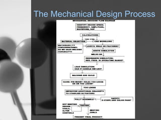
- 6. The Mechanical Design Process
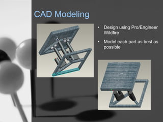
- 7. CAD Modeling ? Design using Pro/Engineer Wildfire ? Model each part as best as possible
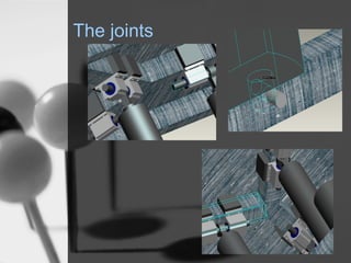
- 8. The joints
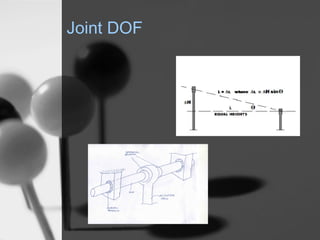
- 9. Joint DOF
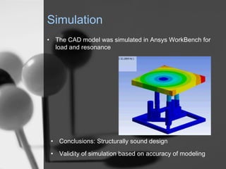
- 10. Simulation ? The CAD model was simulated in Ansys WorkBench for load and resonance ? Conclusions: Structurally sound design ? Validity of simulation based on accuracy of modeling
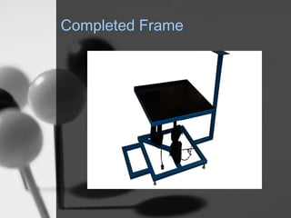
- 11. Completed Frame
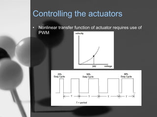
- 12. Controlling the actuators ? Nonlinear transfer function of actuator requires use of PWM
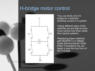
- 13. H-bridge motor control ?You can think of an H- bridge as 4 switches directing current in a system ?Using different pairs of the switches we are able to have more control over than motor than typical systems ?Replacing these switches with MOSFETí»s or (Metal- Oxide Semiconductor Field- Effect Transistors) we can begin to see the true form of the H-bridge.
- 14. Design Issues ? MOSFETí»s need to be turned on with a +12V from gate to source thus requiring external circuitry or driver IC to switch them properly. ? Actuators being used are very high power and create many possible problems on the FETí»s unless circuit protection is in place. ? It can also be very difficult to switch direction on motors as large as needed at a rate that will be acceptable for the design.
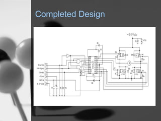
- 15. Completed Design
- 16. Budget Analysis ? A rough estimate of the cost including cost of labor is in the range of $10,000 ? This cost keeps the design close to existing Shaker Tables on the market. ? Some of our budget came from a $2500 USOAR grant received in the Spring of 2006. ? Special thanks to Danaher Motion for donating many of the parts needed for the frame and taking the time to help us out when we ran into problems
- 17. Functional Testing ? H-bridge driver system has been fully tested and design said to be complete ? PIC code can produce basic PWM, but not PWM-encoded harmonic motion ? Current system can run each of the 3 actuators and have been tested, although in attempts to run all three in one system all attempts have resulted in a changing of broken parts ? Based on crude estimates, the motion meets the design specifications based on ? a = -ªÏ^2*x
