際際滷

際際滷Share a Scribd company logo
SI58_SKETCHES_EVAL
SI58_SKETCHES_EVAL
SI58_SKETCHES_EVAL
SI58_SKETCHES_EVAL
SI58_SKETCHES_EVAL
SI58_SKETCHES_EVAL
BILL OF MATERIAL
Evaluator: Kevin Wilson  Field Engineer Date: 9/6/11
Unit: 2 Building: Turbine Elevation: 649
Description of Material Order:
Material for temporary support of 6 & 8 pipe between Col. Rows T10 & T11 & D & H.
Materials:
Item No. Reqd Description
1 6 Adjustable Clevis Hanger, Anvil Fig. 260 for 8 Pipe, Plain Finish
2 16 他 Flat Washer, Matl: F436
3 24 他 Heavy Hex Nut, Matl: A563
4 8 他 Fully Threaded Round Bar, 16 Ft. Lg., Matl: A36 (Cut as Required)
5 5 Universal Beam Clamp, Anvil Fig. 292, Size 4 for 他 Rod, Plain Finish
6 3 Universal Beam Clamp, Anvil Fig. 292, Size 5 for 他 Rod, Plain Finish
7 1 Standard Riser Clamp, Anvil Fig. 40 for 8 Pipe, Matl: Carbon Steel, Plain Finish
8 2 Adjustable Clevis Hanger, Anvil Fig. 260 for 6 Pipe, Plain Finish
9 16 Rod Coupling, Anvil Fig. 135, for 他 Rod, Straight, Plain Finish
FIELD ENGINEERING EVALUATION  SI58
Page 1 of 1
Evaluator: Kevin Wilson  Field Engineer Date: 8/24/11
Unit: 2 Building: Turbine Elevation: Floor El. 649
Location: Between Col. Rows D and H and Col. Rows T9 and T11
References:
1. 3BW0404-OO-01 - Mechanical Drains and Vents & Misc. Piping
2. 3BW0404-OO-42 - Mechanical Drains and Vents & Misc. Piping
Problem Description:
There is an 8 Pipe running from condenser at a location approx. 16 West of Col. Row E to the south and
then parallel to Col Row T11 then thru a penetration in the floor to El. 629. The pipe has no permanent or
temporary supports installed. There are only cables and turnbuckles installed. There is also a 6 pipe that
runs parallel to the 8 pipe. The 6 pipe has some permanent supports installed, but it lacks about 3 of them. It
is also suspended by cables.
Evaluation Summary:
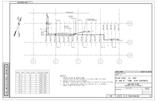
The piping is 8 Sch. 120 which weighs 60.63 lbs./lin. ft. The 6 piping is assumed to be Sch. 120 as well and
weighs 36.39 lbs/ lin. ft. The loads are calculated based on those assumptions. The loads calculated for each
support are shown on SI58_Sketch_1. New supports should be installed as shown on the attached sketches.

More Related Content

SI58_SKETCHES_EVAL

  • 7. BILL OF MATERIAL Evaluator: Kevin Wilson Field Engineer Date: 9/6/11 Unit: 2 Building: Turbine Elevation: 649 Description of Material Order: Material for temporary support of 6 & 8 pipe between Col. Rows T10 & T11 & D & H. Materials: Item No. Reqd Description 1 6 Adjustable Clevis Hanger, Anvil Fig. 260 for 8 Pipe, Plain Finish 2 16 他 Flat Washer, Matl: F436 3 24 他 Heavy Hex Nut, Matl: A563 4 8 他 Fully Threaded Round Bar, 16 Ft. Lg., Matl: A36 (Cut as Required) 5 5 Universal Beam Clamp, Anvil Fig. 292, Size 4 for 他 Rod, Plain Finish 6 3 Universal Beam Clamp, Anvil Fig. 292, Size 5 for 他 Rod, Plain Finish 7 1 Standard Riser Clamp, Anvil Fig. 40 for 8 Pipe, Matl: Carbon Steel, Plain Finish 8 2 Adjustable Clevis Hanger, Anvil Fig. 260 for 6 Pipe, Plain Finish 9 16 Rod Coupling, Anvil Fig. 135, for 他 Rod, Straight, Plain Finish
  • 8. FIELD ENGINEERING EVALUATION SI58 Page 1 of 1 Evaluator: Kevin Wilson Field Engineer Date: 8/24/11 Unit: 2 Building: Turbine Elevation: Floor El. 649 Location: Between Col. Rows D and H and Col. Rows T9 and T11 References: 1. 3BW0404-OO-01 - Mechanical Drains and Vents & Misc. Piping 2. 3BW0404-OO-42 - Mechanical Drains and Vents & Misc. Piping Problem Description: There is an 8 Pipe running from condenser at a location approx. 16 West of Col. Row E to the south and then parallel to Col Row T11 then thru a penetration in the floor to El. 629. The pipe has no permanent or temporary supports installed. There are only cables and turnbuckles installed. There is also a 6 pipe that runs parallel to the 8 pipe. The 6 pipe has some permanent supports installed, but it lacks about 3 of them. It is also suspended by cables. Evaluation Summary: The piping is 8 Sch. 120 which weighs 60.63 lbs./lin. ft. The 6 piping is assumed to be Sch. 120 as well and weighs 36.39 lbs/ lin. ft. The loads are calculated based on those assumptions. The loads calculated for each support are shown on SI58_Sketch_1. New supports should be installed as shown on the attached sketches.