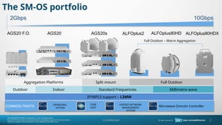
2. AGS20s
AGS20
Split mount
Aggregation Platforms
AGS20 F.O.
CORE
UNIT
OPERATING
SYSTEM
Full Outdoor ¨C Macro Aggregation
ALFOplus80HD
ALFOplus2
UNIFIED NETWORK
MANAGEMENT
SYSTEM
ALFOplus80HDX
2Gbps 10Gbps
COMMON TRAITS
Standard Frequencies Millimetre wave
Full Outdoor
Indoor
Outdoor
IP/MPLS support ¨C L3MW
Microwave Domain Controller
SDC-6
NMS-5
SM-OS
The SM-OS portfolio
Confidential 2
3. Confidential 3
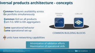
COMMON BUILDING BLOCKS
Common features availability across
the portfolio simultaneously
Same operational behavior
Same operational set-up
Common GUI on all products
from F.O. MW to Eth aggregators
All units have networking capabilities
iversal products architecture - concepts
Minimization of validation efforts
Maximization of operational skills
4. 4
Highlights:
Up to 4 IF Ports
Native & PWE3 TDM
ITU-T T-BC Phase Synch
Layer2 and Layer3 (IP/MPLS)
Embedded Multiband LAG (Hybrid LAG)
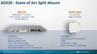
AGS20 - State of Art Split Mount
AGS-20
4096 QAM - 112 MHz
4 Gb/s Radio capacity in 1RU
10 Gb Ethernet
ASNK ODU
4 to 42 GHz
High Tx Power
Highlights:
Leading power consumption
(10W)
Small: 2Kg, 1.7liter
SIAE In House RF technology
Confidential
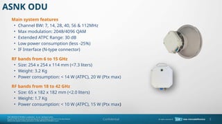
5. ASNK ODU
5
Main system features
? Channel BW: 7, 14, 28, 40, 56 & 112MHz
? Max modulation: 2048/4096 QAM
? Extended ATPC Range: 30 dB
? Low power consumption (less -25%)
? IF Interface (N-type connector)
RF bands from 6 to 15 GHz
? Size: 254 x 254 x 114 mm (<7.3 liters)
? Weight: 3.2 Kg
? Power consumption: < 14 W (ATPC), 20 W (Ptx max)
RF bands from 18 to 42 GHz
? Size: 65 x 182 x 182 mm (<2.0 liters)
? Weight: 1.7 Kg
? Power consumption: < 10 W (ATPC), 15 W (Ptx max)
Confidential
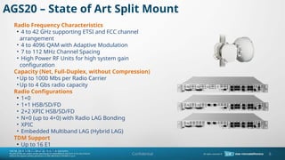
6. Radio Frequency Characteristics
? 4 to 42 GHz supporting ETSI and FCC channel
arrangement
? 4 to 4096 QAM with Adaptive Modulation
? 7 to 112 MHz Channel Spacing
? High Power RF Units for high system gain
configuration
Capacity (Net, Full-Duplex, without Compression)
? Up to 1000 Mbs per Radio Carrier
? Up to 4 Gbs radio capacity
Radio Configurations
? 1+0
? 1+1 HSB/SD/FD
? 2+2 XPIC HSB/SD/FD
? N+0 (up to 4+0) with Radio LAG Bonding
? XPIC
? Embedded Multiband LAG (Hybrid LAG)
TDM Support
? Up to 16 E1
? Up to 2x STM1
AGS20 ¨C State of Art Split Mount
6
Confidential
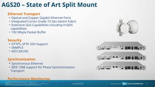
7. Ethernet Transport
? Optical and Copper Gigabit Ethernet Ports
? Integrated Carrier Grade 72 Gbs Switch Fabric
? Extensive QoS Capabilities including H-QOS
capabilities
? 192 Mbyte Packet Buffer
Security
? HTTPS, SFTP, SSH Support
? SNMPv3
? AES128/256
Synchronisation
? Synchronous Ethernet
? IEEE 1588 support for Phase Synchronization
Transport
Performance Monitoring
? Extensive set of Radio, Ethernet and TDM PM
AGS20 ¨C State of Art Split Mount
7
Confidential
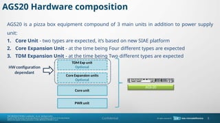
8. AGS20 Hardware composition
Core unit
Core Expansion units
Optional
TDM Exp unit
Optional
PWR unit
HWconfiguration
dependant
AGS-20
AGS20 is a pizza box equipment compound of 3 main units in addition to power supply
unit:
1. Core Unit - two types are expected, it¡¯s based on new SIAE platform
2. Core Expansion Unit - at the time being Four different types are expected
3. TDM Expansion Unit - at the time being Two different types are expected
Core unit
Core Expansion units
Optional
TDM Exp unit
Optional
PWR unit
HWconfiguration
dependant
AGS-20
8
Confidential
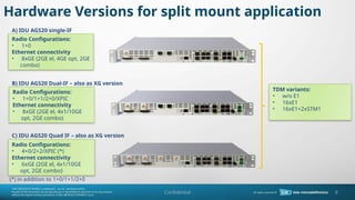
9. Hardware Versions for split mount application
A) IDU AGS20 single-IF
B) IDU AGS20 Dual-IF ¨C also as XG version
C) IDU AGS20 Quad IF ¨C also as XG version
(*) in addition to 1+0/1+1/2+0
Radio Configurations:
? 1+0/1+1/2+0/XPIC
Ethernet connectivity
? 8xGE (2GE el, 4x1/10GE
opt, 2GE combo)
TDM variants:
? w/o E1
? 16xE1
? 16xE1+2xSTM1
Radio Configurations:
? 1+0
Ethernet connectivity
? 8xGE (2GE el, 4GE opt, 2GE
combo)
Radio Configurations:
? 4+0/2+2/XPIC (*)
Ethernet connectivity
? 6xGE (2GE el, 4x1/10GE
opt, 2GE combo)
9
Confidential
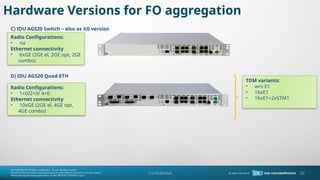
10. Hardware Versions for FO aggregation
C) IDU AGS20 Switch ¨C also as XG version
D) IDU AGS20 Quad-ETH
TDM variants:
? w/o E1
? 16xE1
? 16xE1+2xSTM1
Radio Configurations:
? na
Ethernet connectivity
? 6xGE (2GE el, 2GE opt, 2GE
combo)
Radio Configurations:
? 1+0/2+0/ 4+0
Ethernet connectivity
? 10xGE (2GE el, 4GE opt,
4GE combo)
10
Confidential
11. 11
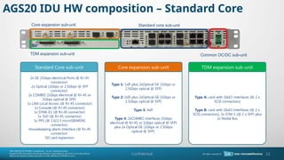
AGS20 IDU HW composition ¨C Standard Core
2x GE (1Gbps electrical Ports @ RJ-45
connector)
2x Optical (1Gbps or 2.5Gbps @ SFP
connector)
2x COMBO (1Gbps electrical @ RJ-45 or
1Gbps optical @ SFP)
1x LAN Local Access (@ RJ-45 connector)
1x Console (@ RJ-45 connector)
1x SYNK-E1 (@ RJ-45 connector)
1x ToD (@ RJ-45 connector)
1x PPS (@ 1.0/2.3 microSIEMENS
connector)
Housekeeping alarm Interface (@ RJ-45
connector)
SD card expansion
Standard Core sub-unit
Type 1: 1xIF plus 2xOptical GE (1Gbps or
2.5Gbps optical @ SFP)
Type 2: 2xIF plus 2xOptical GE (1Gbps or
2.5Gbps optical @ SFP)
Type 3: 4xIF
Type 4: 2xCOMBO interfaces (1Gbps
electrical @ RJ-45 or 1Gbps optical @ SFP)
plus 2x Optical GE (1Gbps or 2.5Gbps
optical @ SFP).
Core expansion sub-unit
Type A: card with 16xE1 interfaces (@ 2 x
SCSI connectors)
Type B: card with 16xE1 interfaces (@ 2 x
SCSI connectors), 2x STM-1 (@ 2 x SFP) plus
2x Nodal Bus
TDM expansion sub-unit
Core expansion sub-unit Standard core sub-unit
TDM expansion sub-unit Common DC/DC sub-unit
Confidential
12. 12
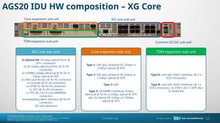
AGS20 IDU HW composition ¨C XG Core
2x Optical XG (10 Gbps optical Ports @
SFP+ connector)
2x GE (1Gbps electrical Ports @ RJ-45
connector)
2x COMBO (1Gbps electrical @ RJ-45 or
1Gbps optical @ SFP)
1x LAN Local Access (@ RJ-45 connector)
1x Console (@ RJ-45 connector)
1x SYNK-E1 (@ RJ-45 connector)
1x ToD (@ RJ-45 connector)
1x PPS (@ 1.0/2.3 microSIEMENS
connector)
Housekeeping alarm Interface (@ RJ-45
connector)
SD card expansion
XG Core sub-unit
Type 1: 1xIF plus 2xOptical GE (1Gbps or
2.5Gbps optical @ SFP)
Type 2: 2xIF plus 2xOptical GE (1Gbps or
2.5Gbps optical @ SFP)
Type 3: 4xIF
Type 4: 2xCOMBO interfaces (1Gbps
electrical @ RJ-45 or 1Gbps optical @ SFP)
plus 2x Optical GE (1Gbps or 2.5Gbps
optical @ SFP).
Core expansion sub-unit
Type A: card with 16xE1 interfaces (@ 2 x
SCSI connectors)
Type B: card with 16xE1 interfaces (@ 2 x
SCSI connectors), 2x STM-1 (@ 2 x SFP) plus
2x Nodal Bus
TDM expansion sub-unit
Core expansion sub-unit XG core sub-unit
TDM expansion sub-unit Common DC/DC sub-unit
Confidential
13. 13
L1 net radio throughput per carrier
Confidential
MODULATION
TYPE
NET RADIO THROUGHPUT [Mbit/s] NET RADIO THROUGHPUT WITH XPIC [Mbit/s]
CHANNEL BANDWIDTH [MHz] CHANNEL BANDWIDTH [MHz]
7 14 28 40 56 112 14 28 40 56 112
4QAMs 8.5 17.5 36.5 51.0 72.0 142.5 17.0 34.5 49.0 70.0 142.5
4QAM 10.0 20.5 42.0 59.5 84.5 167.5 19.5 41.0 57.5 82.0 167.5
16QAMs 17.5 35.5 72.5 102.0 144.0 285.5 35.5 71.5 100.0 140.0 285.5
16QAM 20.5 42.5 83.5 116.5 165.5 330.0 42.5 82.5 116.5 162.0 330.0
32QAM 24.5 50.5 104.5 146.0 207.0 412.0 50.5 103.5 145.0 202.0 412.0
64QAM 30.0 63.5 131.5 184.5 262.0 525.0 63.5 129.5 182.0 258.0 525.0
128QAM 36.0 75.5 156.5 219.0 310.5 623.0 76.0 156.5 216.0 306.0 623.0
256QAM 42.0 87.5 180.0 253.0 358.5 718.0 87.0 177.0 248.5 353.0 718.0
512QAM 46.5 97.5 200.0 281.5 399.5 799.5 97.0 197.0 277.0 393.0 799.5
1024QAM 51.5 107.0 223.5 314.5 446.0 893.5 106.0 220.0 309.5 439.0 839.5
2048QAM - 111.0 233.5 332.0 471.5 937.0 - - 460.5 937.0
4096QAM - - 257.0 518.0 1024.0 - - - -
Note 1: header compression also available for additional 20-30% of gain on Ethernet traffic (depending on type of traffic).
Note 2: 112 MHz channels availability as per ITU standards.
15. 15
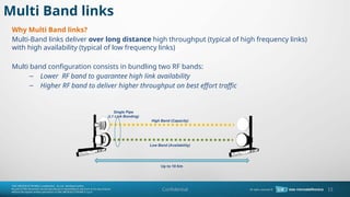
Multi Band links
Why Multi Band links?
Multi-Band links deliver over long distance high throughput (typical of high frequency links)
with high availability (typical of low frequency links)
Multi band configuration consists in bundling two RF bands:
¨C Lower RF band to guarantee high link availability
¨C Higher RF band to deliver higher throughput on best effort traffic
High Band (Capacity)
Low Band (Availability)
Single Pipe
(L1 Link Bonding)
Up to 10 Km
Confidential
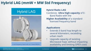
16. Hybrid LAG (mmW + MW Std Frequency)
Confidential 16
Hybrid LAG
A std frequency band with an E-band 80GHz
Hybrid Radio LAG
Combines Ultra high capacity of E-
Band Radio with the
Higher Availability of a standard
licensed frequency band
Applications
? Extends E-band hop length to
several kilometers, exceeding
urban reach
? Upgrade capacity of existing
Microwave hops without impacting
availability and limiting OPEX costs
impact
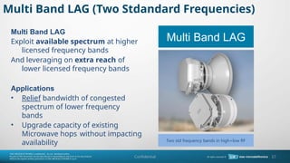
17. Multi Band LAG (Two Stdandard Frequencies)
Confidential 17
Multi Band LAG
Two std frequency bands in high+low RF
Multi Band LAG
Exploit available spectrum at higher
licensed frequency bands
And leveraging on extra reach of
lower licensed frequency bands
Applications
? Relief bandwidth of congested
spectrum of lower frequency
bands
? Upgrade capacity of existing
Microwave hops without impacting
availability
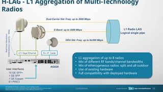
18. L1 Radio LAG
Logical single pipe
N x IF Cable
E-Band: up to 2000 Mbps
AGS20
10 GE SFP+
1 GE SFP
1 GE Copper
E1 PWE3
H-LAG - L1 Aggregation of Multi-Technology
Radios
18
Dual-Carrier Std. Freq: up to 2000 Mbps
ODU Std. Freq: up to Nx500 Mbps
2.5 Giga Ethernet
User interfaces
? L1 aggregation of up to 8 radios
? Mix of different RF bands/channel bandwidths
? Mix of etherogeneous radios: split and all outdoor
? Use of existing hardware
? Full compatibility with deployed hardware
Real
time
interaction
Instantaneous
capacity
-
delay
Confidential
19. Confidential 19
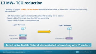
L3 MW¨C TCO reduction
Capability to support IP/MPLS in Micorwave avoiding external Router is now a quite common option in many
Microwave RFQ
? 40% Transmission capex reduction can be achieved by avoiding CSR co-location
? Support of Dual-Homing in dual Fiber/MW site connectivity
? Support of Mesh Networks topology upgrade
Microwave IDU
L3 Cell Site Router L3 Microwave IDU
Layer2 Microwave Layer3 Microwave
Tested in live Mobile Network demonstrated interworking with IP vendors
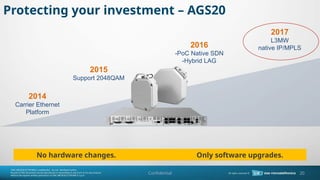
20. Protecting your investment ¨C AGS20
2014
Carrier Ethernet
Platform
2015
Support 2048QAM
2016
-PoC Native SDN
-Hybrid LAG
2017
L3MW
native IP/MPLS
No hardware changes. Only software upgrades.
20
Confidential
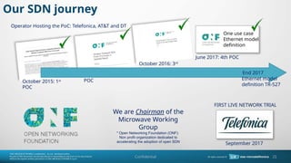
21. Our SDN journey
Confidential 21
October 2015: 1st
POC
April 2016: 2nd
POC
October 2016: 3rd
POC
FIRST LIVE NETWORK TRIAL
June 2017: 4th POC
One use case
Ethernet model
definition
Ethernet model
definition TR-527
End 2017
September 2017
Operator Hosting the PoC: Telefonica, AT&T and DT
* Open Networking Foundation (ONF):
Non profit organization dedicated to
accelerating the adoption of open SDN
We are Chairman of the
Microwave Working
Group
24. Confidential
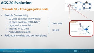
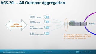
AGS-20L Multi-technology pre-aggregation
Node
Capacity
? 100 Gbps full-duplex switching
capacity
? 60 Gbps capacity Radio Side/Access
? 40 Gbps Line Side
Connettivity
? Multiple 10 GbE ports SFP+
? Multiple 1 / 2.5 GbE ports (Copper &
SFP)
? E1 Native/PWE3 and STM-1
? Radio IF ports for ODUs
? OTN Line interface
Networking
? L2 Ethernet
? L3 IP/MPLS
? OTN Encapsulation
Microwave Configuration
? Multiple N+0 on IF-ODUs
? Multiple N+0 on Full Outdoor
? Multiband Links
Redundancy
? Full redundant 2RU HW architecture
? Data plane, Control Plane, Management Plane
protection
? Hot-Swappable HW units
Management
? SNMPv3
? Netconf/YANG for SDN Controllers
? HTTPS/SFTP/SSH
24
25. Confidential
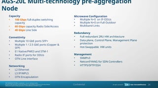
AGS-20L - Layout
RIM Module
FAN
Power
Supply 100 Gbs CORE Unit
RIM Module
LIM Module
RIM Module
100 Gbs CORE Unit
RIM Module
LIM Module
FAN
Power
Supply
? RIM: Radio Interface Module for split or all outdoor radios
? RIM slots can be used to extend line connectivity, if CORE+LIM fan out
is not sufficient
? LIM: Line Interface Module
? LIM slots can be used also for connectivity to all
outdoor radios
25
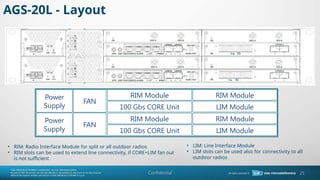
26. Confidential
RIM Module
FAN
Power
Supply 100 Gbs CORE Unit
RIM Module
LIM Module
RIM Module
100 Gbs CORE Unit
RIM Module
LIM Module
FAN
Power
Supply
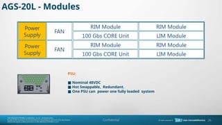
PSU:
Nominal 48VDC
¡ö
Hot Swappable, Redundant.
¡ö
One PSU can power one fully loaded system
¡ö
AGS-20L - Modules
26
27. Confidential
RIM Module
FAN
Power
Supply 100 Gbs CORE Unit
RIM Module
LIM Module
RIM Module
100 Gbs CORE Unit
RIM Module
LIM Module
FAN
Power
Supply
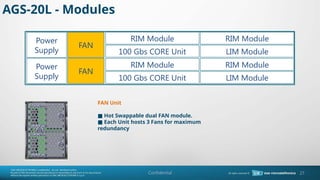
FAN Unit
Hot Swappable dual FAN module.
¡ö
Each Unit hosts 3 Fans for maximum
¡ö
redundancy
AGS-20L - Modules
27
28. Confidential
RIM Module
FAN
Power
Supply 100 Gbs CORE Unit
RIM Module
LIM Module
RIM Module
100 Gbs CORE Unit
RIM Module
LIM Module
FAN
Power
Supply
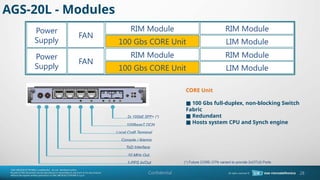
CORE Unit
100 Gbs full-duplex, non-blocking Switch
¡ö
Fabric
Redundant
¡ö
Hosts system CPU and Synch engine
¡ö
2x 10GbE SFP+ (*)
100BaseT DCN
Local Craft Terminal
Console / Alarms
ToD Interface
10 MHz Out
1-PPS In/Out
AGS-20L - Modules
(*) Future CORE-OTN variant to provide 2xOTU2 Ports
28
29. Confidential
RIM Module
FAN
Power
Supply 100 Gbs CORE Unit
RIM Module
LIM Module
RIM Module
100 Gbs CORE Unit
RIM Module
LIM Module
FAN
Power
Supply
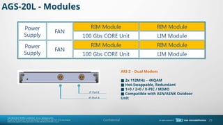
ARI-2 ¨C Dual Modem
2x 112MHz ¨C 4KQAM
¡ö
Hot-Swappable, Redundant
¡ö
1+0 / 2+0 / X-PIC / MIMO
¡ö
Compatible with ASN/ASNK Outdoor
¡ö
Unit
IF Port B
IF Port A
AGS-20L - Modules
29
30. Confidential
RIM Module
FAN
Power
Supply 100 Gbs CORE Unit
RIM Module
LIM Module
RIM Module
100 Gbs CORE Unit
RIM Module
LIM Module
FAN
Power
Supply
DRI-8 ¨C 8x Gigabit Ethernet
NNI ¨C UNI Modes
¡ö
Hot-Swappable, Redundant
¡ö
1 / 2.5 Gbs Full-Outdoor Connectivity
¡ö
4x SFP (1 or 2.5 Gbs)
4x 1000BaseT
AGS-20L - Modules
30
31. Confidential
RIM Module
FAN
Power
Supply 100 Gbs CORE Unit
RIM Module
LIM Module
RIM Module
100 Gbs CORE Unit
RIM Module
LIM Module
FAN
Power
Supply
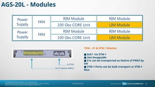
TDM ¨C E1 & STM-1 Module
8xE1 +2x STM-1
¡ö
Hot-Swappable
¡ö
E1s can be transported as Native of PWE3 by
¡ö
SW
STM-1 Ports can be bulk transport or STM-1
¡ö
Mux
2x STM-1
8x E1 (Native-PWE3)
AGS-20L - Modules
31
32. Confidential
RIM Module
FAN
Power
Supply 100 Gbs CORE Unit
RIM Module
LIM Module
RIM Module
100 Gbs CORE Unit
RIM Module
LIM Module
FAN
Power
Supply
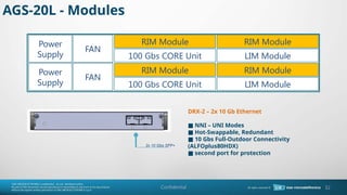
DRX-2 ¨C 2x 10 Gb Ethernet
NNI ¨C UNI Modes
¡ö
Hot-Swappable, Redundant
¡ö
10 Gbs Full-Outdoor Connectivity
¡ö
(ALFOplus80HDX)
second port for protection
¡ö
2x 10 Gbs SFP+
AGS-20L - Modules
32
33. Confidential
10 Gbs
FAN
Power
Supply 100 Gbs CORE Unit
10 Gbs
20 Gbs
10 Gbs
100 Gbs CORE Unit
10 Gbs
20 Gbs
FAN
Power
Supply
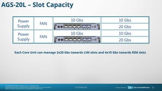
AGS-20L ¨C Slot Capacity
Each Core Unit can manage 2x20 Gbs towards LIM slots and 4x10 Gbs towards RIM slots
33
34. Confidential
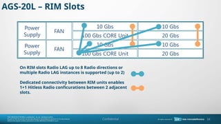
AGS-20L ¨C RIM Slots
On RIM slots Radio LAG up to 8 Radio directions or
multiple Radio LAG instances is supported (up to 2)
Dedicated connectivity between RIM units enables
1+1 Hitless Radio conficurations between 2 adjacent
slots.
10 Gbs
FAN
Power
Supply 100 Gbs CORE Unit
10 Gbs
20 Gbs
10 Gbs
100 Gbs CORE Unit
10 Gbs
20 Gbs
FAN
Power
Supply
34
35. Confidential
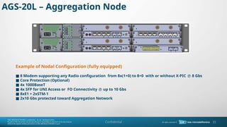
Example of Nodal Configuration (fully equipped)
8 Modem supporting any Radio configuration from 8x(1+0) to 8+0 with or without X-PIC
¡ö ? 8 Gbs
Core Protection (Optional)
¡ö
4x 1000BaseT
¡ö
4x SFP for UNI Access or FO Connectivity
¡ö ? up to 10 Gbs
8xE1 + 2xSTM-1
¡ö
2x10 Gbs protected toward Aggregation Network
¡ö
AGS-20L ¨C Aggregation Node
35
36. Confidential
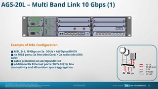
Example of MBL Configuration
MBL 2+1, 10 Gbps on 2x ODUs + ALFOplus80HDX
¡ö
4x 10GE ports: 2x line side (Core) + 2x radio side (DRX
¡ö
card)
cable protection on ALFOplus80HDX
¡ö
additional 8x Ethernet ports (1/2.5 GE) for line
¡ö
connectivity and all outdoor spurs aggregation
AGS-20L ¨C Multi Band Link 10 Gbps (1)
36
3G
10 GE
10 GE prot.
1 GE
IF Radio
L1 LAG
37. Confidential
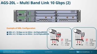
Example of MBL Configuration
MBL 4+1, 10 Gbps on 4x ODUs + ALFOplus80HDX
¡ö
MBL 4+2, 10 Gbps on 4x ODUs + 2x ALFOplus80HDX
¡ö
AGS-20L ¨C Multi Band Link 10 Gbps (2)
37
3G
10 GE
10 GE prot.
1 GE
IF Radio
L1 LAG
3G
10 GE
10 GE prot.
1 GE
IF Radio
L1 LAG
38. Confidential
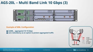
Example of MBL Configuration
2xMBL, aggregated 10+10 Gbps
¡ö
core redundancy as an option to protect aggregated traffic
¡ö
AGS-20L ¨C Multi Band Link 10 Gbps (3)
38
10 GE
10 GE prot.
1 GE
IF Radio
L1 LAG
10GE +10GE
#3: SIAE portfolio strategic approach can be realized thanks to the Universal product architecture, based on common building blocks such as the operating systyem SM-OS and the core unit.
The same platform allows us to have common features across the portfolio, a common graphic interface and the same operational behavior and set up.
#16: HYBRID LAG ¨¨ la principale tecnica che vorremmo perlustrare in questa presentazione.
Applicazione : Estendensione del range tipico delle mmW e/o Upgradare capacit¨¤ di link MW esistenti senza impatto su availibility e limito impatto di costo
#17: MULTI BAND
Viene sfruttato uno spettori HF e uno LF con le rispettive peculiarit¨¤
Applciazione .
-Relief/allegerimento delle bande congestionate
-upgrade capacit¨¤ dei MW esistenti non impattante
dove si coninvolgono ¨¨ la prima delle possibilit¨¤ in uci mmw non vengono coinvolto
#18: Tutte le combimazione delle possibilit¨¤ HW da includere in conf HLAG

![13
L1 net radio throughput per carrier
Confidential
MODULATION
TYPE
NET RADIO THROUGHPUT [Mbit/s] NET RADIO THROUGHPUT WITH XPIC [Mbit/s]
CHANNEL BANDWIDTH [MHz] CHANNEL BANDWIDTH [MHz]
7 14 28 40 56 112 14 28 40 56 112
4QAMs 8.5 17.5 36.5 51.0 72.0 142.5 17.0 34.5 49.0 70.0 142.5
4QAM 10.0 20.5 42.0 59.5 84.5 167.5 19.5 41.0 57.5 82.0 167.5
16QAMs 17.5 35.5 72.5 102.0 144.0 285.5 35.5 71.5 100.0 140.0 285.5
16QAM 20.5 42.5 83.5 116.5 165.5 330.0 42.5 82.5 116.5 162.0 330.0
32QAM 24.5 50.5 104.5 146.0 207.0 412.0 50.5 103.5 145.0 202.0 412.0
64QAM 30.0 63.5 131.5 184.5 262.0 525.0 63.5 129.5 182.0 258.0 525.0
128QAM 36.0 75.5 156.5 219.0 310.5 623.0 76.0 156.5 216.0 306.0 623.0
256QAM 42.0 87.5 180.0 253.0 358.5 718.0 87.0 177.0 248.5 353.0 718.0
512QAM 46.5 97.5 200.0 281.5 399.5 799.5 97.0 197.0 277.0 393.0 799.5
1024QAM 51.5 107.0 223.5 314.5 446.0 893.5 106.0 220.0 309.5 439.0 839.5
2048QAM - 111.0 233.5 332.0 471.5 937.0 - - 460.5 937.0
4096QAM - - 257.0 518.0 1024.0 - - - -
Note 1: header compression also available for additional 20-30% of gain on Ethernet traffic (depending on type of traffic).
Note 2: 112 MHz channels availability as per ITU standards.](https://image.slidesharecdn.com/siaemic-ags20technicalproductpresentationp-250323182121-a599c1a3/85/siaemic-AGS20-technical-product-presentation-P-04-18-pptx-13-320.jpg)