simulation flow_general_presentation_eng_sem_bridge
?Download as PPT, PDF?
1 like?387 views

The document discusses fluid flow analysis software SolidWorks Flow Simulation. It begins with an agenda that includes explaining what fluid flow analysis is, the benefits of investing in it, and why SolidWorks Flow Simulation is a good option. It then provides examples of how SolidWorks Flow Simulation has been used to analyze electronics cooling, HVAC ventilation, and medical device design. The document concludes with a demonstration of how SolidWorks Flow Simulation can be used to analyze fluid flow through a ball valve.


simulation flow_general_presentation_eng_sem_bridge
- 1. 1 3DS.COM?DassaultSyst¨¨mes|ConfidentialInformation|11/14/16|ref.:3DS_Document_20123DS.COM?DassaultSyst¨¨mes|ConfidentialInformation|11/14/16|ref.:3DS_Document_2012 SolidWorks Flow Simulation ¨C Fluid Flow Analysis Inside SolidWorks <Presenter Name> <Date>
- 2. 2 3DS.COM?DassaultSyst¨¨mes|ConfidentialInformation|11/14/16|ref.:3DS_Document_2012 Agenda What is Static & Fluid Flow Analysis and why invest in it? Why SolidWorks Flow Simulation? Real life examples solved using SolidWorks Flow Simulation SolidWorks Flow Simulation demonstration Q&A
- 3. 3 3DS.COM?DassaultSyst¨¨mes|ConfidentialInformation|11/14/16|ref.:3DS_Document_2012 What is Static and Fluid Flow Analysis?
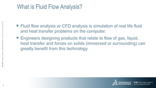
- 4. 4 3DS.COM?DassaultSyst¨¨mes|ConfidentialInformation|11/14/16|ref.:3DS_Document_2012 What is Fluid Flow Analysis? Fluid flow analysis or CFD analysis is simulation of real life fluid and heat transfer problems on the computer. Engineers designing products that relate to flow of gas, liquid, heat transfer and forces on solids (immersed or surrounding) can greatly benefit from this technology
- 5. 5 3DS.COM?DassaultSyst¨¨mes|ConfidentialInformation|11/14/16|ref.:3DS_Document_2012 Why Invest in Fluid Flow Analysis? Improve efficiency & performance Improve quality/Innovate Reduce weight and cost Ensure safety & reliability
- 6. 6 3DS.COM?DassaultSyst¨¨mes|ConfidentialInformation|11/14/16|ref.:3DS_Document_2012 Reduce Experimental Testing or Prototyping Faster lead time Less expensive than wind-tunnel testing or prototyping Ability to investigate several options (ˇ°What-if studiesˇ±) More comprehensive results (Visualization) Requires less effort (Manpower)
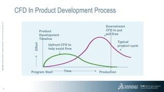
- 7. 7 3DS.COM?DassaultSyst¨¨mes|ConfidentialInformation|11/14/16|ref.:3DS_Document_2012 Program Start ProductionTime Effort Product Development Timeline Upfront CFD to help avoid fires Downstream CFD to put out fires Typical product cycle CFD In Product Development Process
- 8. 8 3DS.COM?DassaultSyst¨¨mes|ConfidentialInformation|11/14/16|ref.:3DS_Document_2012 Agenda What is Fluid Flow Analysis and why invest in it? Why SolidWorks Flow Simulation? Real life examples solved using SolidWorks Flow Simulation SolidWorks Flow Simulation demonstration Q&A
- 9. 9 3DS.COM?DassaultSyst¨¨mes|ConfidentialInformation|11/14/16|ref.:3DS_Document_2012 Why SolidWorks Flow Simulation? Single windows integration with SolidWorks Automatic associativity with SolidWorks geometry Automatic fluid region detection Easy to use and very short learning curve Cost effective
- 10. 10 3DS.COM?DassaultSyst¨¨mes|ConfidentialInformation|11/14/16|ref.:3DS_Document_2012 Technical Capabilities Incompressible (liquid or gas) or compressible (gas) viscous flow including subsonic, transonic and supersonic regimes External and/or internal flows Non-Newtonian Flows (Viscous fluids such as blood) Automatic laminar/turbulent solution with transition Wall roughness model One component or up to ten independent species Forced, free or mixed convection Conjugated heat transfer (fluid, solid), conduction and convection Porous Media model Radiation Time-dependent fluid flow, heat and mass transfer analysis
- 11. 11 3DS.COM?DassaultSyst¨¨mes|ConfidentialInformation|11/14/16|ref.:3DS_Document_2012 Accepted by Market Leadersˇ Lufthansa Mitsubishi Heavy Industries Matsushita Industrial Equipment SANYO NASA Ames Baker Oil Tools Evergreen Packaging Parker Hannifin Halliburton Energy Services Kyushu Nissho Co MicroMetl Purolator-Facet Inc. Resmed Swagelok MediSystems Cambridgeport Systems GE Medical Sturman Industries Johnson Corporation Ceramic Fuel Energy Products
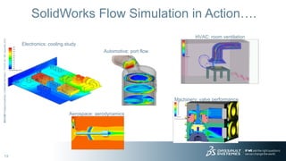
- 13. 13 3DS.COM?DassaultSyst¨¨mes|ConfidentialInformation|11/14/16|ref.:3DS_Document_2012 SolidWorks Flow Simulation in Actionˇ. Electronics: cooling study Automotive: port flow HVAC: room ventilation Aerospace: aerodynamics Machinery: valve performance
- 14. 14 3DS.COM?DassaultSyst¨¨mes|ConfidentialInformation|11/14/16|ref.:3DS_Document_2012 SolidWorks Flow Simulation in Actionˇ. Electronics: cooling study Automotive: port flow HVAC: room ventilation Aerospace: aerodynamics Machinery: valve performance
- 15. 15 3DS.COM?DassaultSyst¨¨mes|ConfidentialInformation|11/14/16|ref.:3DS_Document_2012 Agenda What is Fluid Flow Analysis and why invest in it? Why SolidWorks Flow Simulation? Real life examples solved using SolidWorks Flow Simulation SolidWorks Flow Simulation demonstration Q&A
- 16. 16 3DS.COM?DassaultSyst¨¨mes|ConfidentialInformation|11/14/16|ref.:3DS_Document_2012 Real Life Example: Electronics Design Challenge: Identify and select the best heat sink shape for a chip installed in an electronic enclosure
- 17. 17 3DS.COM?DassaultSyst¨¨mes|ConfidentialInformation|11/14/16|ref.:3DS_Document_2012 Real Life Example: Electronics The Goal: Determine the lowest main chip temperature using two different heat sink designs Heat Sink 1 Heat Sink 2
- 18. 18 3DS.COM?DassaultSyst¨¨mes|ConfidentialInformation|11/14/16|ref.:3DS_Document_2012 Real Life Example: Electronics Approach: Allow engineer test each design and choose the best option
- 19. 19 3DS.COM?DassaultSyst¨¨mes|ConfidentialInformation|11/14/16|ref.:3DS_Document_2012 Real Life Example: Electronics Temperature cut plots (front view) obtained for heat sinks The 30-color palette in the 50-100oF range Heat Sink 1 Heat Sink 2
- 20. 20 3DS.COM?DassaultSyst¨¨mes|ConfidentialInformation|11/14/16|ref.:3DS_Document_2012 Real Life Example: Electronics Temperature cut plots (top view) obtained for heat sinks The 30-color palette range of 50-100oF Heat Sink 1 Heat Sink 2
- 21. 21 3DS.COM?DassaultSyst¨¨mes|ConfidentialInformation|11/14/16|ref.:3DS_Document_2012 Real Life Example: Electronics Conclusion The results show a 17.5% reduction in solid temperatures in heat sink No. 2. Therefore, heat sink No. 2 is recommended.
- 22. 22 3DS.COM?DassaultSyst¨¨mes|ConfidentialInformation|11/14/16|ref.:3DS_Document_2012 Real Life Example: Natural Convection Design Challenge: To determine cost effective techniques for increased cooling on electronic equipment. An off the shelf heat sink has been mandated, and its design cannot be changed. Back face in contact with hot enclosure Direction of gravity
- 23. 23 3DS.COM?DassaultSyst¨¨mes|ConfidentialInformation|11/14/16|ref.:3DS_Document_2012 Real Life Example: Natural Convection The Goal: To determine if the addition of a ˇ°shieldˇ± significantly improves the performance of the heat sink No. 1 Design without shield No. 2 Design with shield
- 24. 24 3DS.COM?DassaultSyst¨¨mes|ConfidentialInformation|11/14/16|ref.:3DS_Document_2012 Real Life Example: Natural Convection Approach: Allow the engineer to compute the temperatures before the design is prototyped
- 25. 25 3DS.COM?DassaultSyst¨¨mes|ConfidentialInformation|11/14/16|ref.:3DS_Document_2012 Real Life Example: Natural Convection Velocity Cut Plot Warmer colors designate higher vertical velocity (The ˇ°With Shieldˇ± model has greater velocity around the heat sink fins) Without Shield With Shield
- 26. 26 3DS.COM?DassaultSyst¨¨mes|ConfidentialInformation|11/14/16|ref.:3DS_Document_2012 Real Life Example: Natural Convection Velocity Cut Plots through a vertical section Warmer colors designate higher vertical velocity (The ˇ°With Shieldˇ± model has much greater velocities within the shield) Without Shield With Shield
- 27. 27 3DS.COM?DassaultSyst¨¨mes|ConfidentialInformation|11/14/16|ref.:3DS_Document_2012 Real Life Example: Natural Convection Temperature Cut Plots through a cross section Warmer colors designate higher temperatures (The ˇ°With Shieldˇ± model transfers more heat to the air) Without Shield With Shield
- 28. 28 3DS.COM?DassaultSyst¨¨mes|ConfidentialInformation|11/14/16|ref.:3DS_Document_2012 Real Life Example: Natural Convection Solid Temperature Cut Plot through a cross section Warmer colors designate higher temperatures (The ˇ°With Shieldˇ± model is dramatically cooler) Without Shield With Shield
- 29. 29 3DS.COM?DassaultSyst¨¨mes|ConfidentialInformation|11/14/16|ref.:3DS_Document_2012 Real Life Example: Natural Convection Conclusion: The results show a 10.9% decrease in average temperature when comparing the two designs. With these findings, it is clear that the addition of a shield significantly improves the design.
- 30. 30 3DS.COM?DassaultSyst¨¨mes|ConfidentialInformation|11/14/16|ref.:3DS_Document_2012 Real Life Example: Medical Device Design Challenge: Identify the best screen shape for a medical suction device -- allow the highest flow rate for a given suction (pressure drop), have limited recirculation within the device, create the most uniform velocity profile at the suction head Flow Direction
- 31. 31 3DS.COM?DassaultSyst¨¨mes|ConfidentialInformation|11/14/16|ref.:3DS_Document_2012 Real Life Example: Medical Device The Goal: Determine the flow rate at a given pressure drop for each of the two screen designs when installed in the suction device Design No. 1 Design No. 2
- 32. 32 3DS.COM?DassaultSyst¨¨mes|ConfidentialInformation|11/14/16|ref.:3DS_Document_2012 Real Life Example: Medical Device Approach EFD allows the engineer to compute the flow rate before the design is prototyped The computed volumetric flow rate for each screen design
- 33. 33 3DS.COM?DassaultSyst¨¨mes|ConfidentialInformation|11/14/16|ref.:3DS_Document_2012 Real Life Example: Medical Device Pressure cut plot for each design Both designs have similar pressure profiles Triangular Cuts Circular Cuts
- 34. 34 3DS.COM?DassaultSyst¨¨mes|ConfidentialInformation|11/14/16|ref.:3DS_Document_2012 Real Life Example: Medical Device Velocity cut plots with velocity vectors for each design Both designs have similar velocity profiles at the suction head Triangular Cuts Circular Cuts
- 35. 35 3DS.COM?DassaultSyst¨¨mes|ConfidentialInformation|11/14/16|ref.:3DS_Document_2012 Real Life Example: Medical Device Trajectory plot showing recirculation zone While both designs have some recirculation, the zone for the triangular design is larger Triangular Cuts Circular Cuts
- 36. 36 3DS.COM?DassaultSyst¨¨mes|ConfidentialInformation|11/14/16|ref.:3DS_Document_2012 Real Life Example: Medical Device Conclusion: The results show a 7.8% higher flow rate using the screen with circular cuts. Both designs have reasonably equal velocity profiles at the suction head. The circular design has a smaller recirculation zone. With these findings, it is clear that the circular design is superior based on our design criteria
- 37. 37 3DS.COM?DassaultSyst¨¨mes|ConfidentialInformation|11/14/16|ref.:3DS_Document_2012 Agenda What is Fluid Flow Analysis and why invest in it? Why SolidWorks Flow Simulation? Real life examples solved using SolidWorks Flow Simulation SolidWorks Flow Simulation demonstration Q&A
- 38. 38 3DS.COM?DassaultSyst¨¨mes|ConfidentialInformation|11/14/16|ref.:3DS_Document_2012 Demonstration ¨C Ball Valve Inlet: Water entering at 0.5 kg/sec Outlet: Water exiting to atmosphere (Static pressure) Goal: Determine the pressure drop across the valve
- 39. 39 3DS.COM?DassaultSyst¨¨mes|ConfidentialInformation|11/14/16|ref.:3DS_Document_2012 Agenda What is Fluid Flow Analysis and why invest in it? Why SolidWorks Flow Simulation? Real life examples solved using SolidWorks Flow Simulation SolidWorks Flow Simulation demonstration Q&A
- 40. 40 3DS.COM?DassaultSyst¨¨mes|ConfidentialInformation|11/14/16|ref.:3DS_Document_2012 Thank You! Visit the SolidWorks website at http://www.solidworks.com to learn more about SolidWorks and its product offerings. Contact your local SolidWorks reseller for information on pricing and training. To find a reseller in your area call: 1-800-693-9000 (US and Canada) +1-978-371-5011 (Outside the US and Canada) My email address: <Your email address>
Editor's Notes
- #2: For webcast only: 10:25 AM ¨C Thank you for joining us for the this. We will begin in about 5 minutes. 10:30 AM ¨C Thank you for joining us for the this webcast. We will begin in just a few minutes. 10:35 AM ¨C Good day to all of you, and thank you for being here to see Flow Simulation ¨C Fluid Flow Analysis Inside SolidWorks. Please note that this webcast is not intended to be a training session but more of a tips and tricks presentation. For SolidWorks training please contact your reseller.
- #3: Today we will cover a basic overview of Fluid Flow or CFD analysis and its benefits. We will also discuss why Flow Simulation is an ideal software for engineers to conduct Fluid Flow Analysis. Then we will show results from real life examples solved using Flow Simulation. After that we will demonstrate SolidWorks & Flow Simulation to show Fluid flow Analysis. Finally, we will have a few minutes of Q & A to answer questions you type in during the presentation. Let us begin with a basic overview and background. Please note we will be using Fluid flow Analysis and CFD analysis interchangeably during this presentation
- #4: To simply state, Fluid flow analysis or CFD analysis is simulation of real life fluid and heat transfer problems on the computer. Any Fluid Flow software converts these real life problems into equations and solves them numerically using the power of computers Engineers designing products that relate to flow of gas, liquid, heat transfer and forces on solids (immersed or surrounding) can greatly benefit from this technology
- #5: To simply state, Fluid flow analysis or CFD analysis is simulation of real life fluid and heat transfer problems on the computer. Any Fluid Flow software converts these real life problems into equations and solves them numerically using the power of computers Engineers designing products that relate to flow of gas, liquid, heat transfer and forces on solids (immersed or surrounding) can greatly benefit from this technology
- #6: Why should you invest in Fluid Flow Analysis Software? To improve the efficiency or performance of your designs. For example a lower drag aircraft fuselage results in lower fuel consumption or less pressure drop through an automotive intake system results in increased horsepower. To improve quality or to come up with new innovative designs. To reduce the cost and weight. For example, by optimizing the airflow in an electronics enclosure will result in a smaller, cheaper, cooling fan. Ensure safety and reliability. So our new car or dishwasher or computer doesnˇŻt break down six months after we buy it.
- #7: Computational fluid dynamics complements or in some cases even replace experimental or wind tunnel testing or prototyping. Conducting a CFD analysis is much faster than manufacturing a prototype or model, instrumenting it, testing it, and getting useful results in the end. CFD analysis is in many cases much cheaper than wind-tunnel testing. Investigating several configurations or design options is relatively simple with CFD. You can get more comprehensive results with CFD. ItˇŻs easy to determine the velocity, pressure, density, temperatureˇˇin a CFD model. To determine all of these quantities in a wind tunnel would be very difficult requiring a large assortment of instruments. tatic taps for surface pressures, multi-hole probes for pressures and velocities in the flow path, thermocouples for temperature, hot wire probes for turbulence quantities. In some cases itˇŻs not possible to measure flow properties, such as in a gas turbine or rocket exhaust due to the extreme temperatures. CFD requires less manual effort than prototyping or wind tunnel testing. Of course CFD does not totally replace experimental testing due to government safety regulations.
- #8: CFD analysis has been traditionally conducted at the end of the product development for verification purposes only. Today companies are beginning to integrate CFD into the design process to help make design changes early in the design cycle. They are realizing the benefits of early flow analysis such as: Increase the quality of their designs by validating them in progress ¨C conducting ˇ°what-ifˇ± studies or optimizing in progress. Designs will not only be better but they will reach the market faster. Allows the dedicated analysis group to concentrate on mission critical designs or final verification.
- #9: Now that we have discussed the benefits and importance of Fluid flow Analysis, lets see why Flow Simulation is the ideal software for it.
- #10: FloWorks belongs to a new generation of fluid analysis software. It has been designed for designers and engineers and is very ease to use compared to traditional Fluid Flow analysis. Flow Simulation is the only embedded flow analysis software inside SolidWorks. It allows users to immediately create designs and analyze them without having to transfer the data to the separate analysis codes. Design engineers rarely accept the first design ¨C multiple variants of a design are created and tested to find an optimum design. Flow Simulation allows the user to create multiple variants of a design and then run the analysis ¨C the software is smart enough to understand that all material properties and the boundary conditions already designated to the first model, apply to its variants as well. Flow Simulation automatically detects the fluid region in the SolidWorks assembly. Most of other Fluid analysis software require the user to create ˇ°negativeˇ± geometry to help the software identify the fluid regions. Flow Simulation is goal-oriented. Users need to solve a problem: for example, minimize pressure in a valve, optimize temperature in a computer cabinet or maximize mass flow thru a specific opening. Instead of having to translate goals into numerical convergence criteria, iteration numbers and relaxation factor (as in the case of CFD software) the user simply tells the software what heˇŻs interested in and starts the design process. Since Flow Simulation is so well integrated inside SolidWorks it has a fairly short learning curve. And lastly, Flow Simulation is more cost effective than other CFD software -- both in terms of monetary and human resources.
- #11: Flow Simulation has extensive set of capabilities to simulate various type of real life problems Includingˇ..
- #12: Flow Simulation is accepted by market leaders and is used by many companies in different industries. Here are just few companies who are using Flow Simulation.
- #13: As you can see, fluid analysis is not only used in the traditional industries such as automotive, aerospace, and defense but also in less traditional markets such as biomedical, HVAC, machines, appliances etc.
- #14: Here are some examples of Flow Simulation in action. Additionally Flow Simulation is being used in several application in different industries such as: In Automotive industry: Flow around vehicles, Coolant flow in engine blocks and cylinder heads Flows in manifolds, valves, nozzles, pumps, catalytic converters, shock absorbers In Electronics and semiconductors Flow and thermal fields in cabinets, chassis, circuit boards Air flow around disk drives Biomedical Flow in biomedical devices, tubes and constrictions Cleansing processes Aerospace/defense External aerodynamics, Flow around submerged bodies Cabin ventilation, Flows in fuel lines and fuel tanks Machine/appliances Draft tubes Fluid flow for removal of waste material HVAC Heat exchangers and regenerators Design of heating and air conditioning distribution systems, Smoke distribution
- #15: Here are some examples of Flow Simulation in action. Additionally Flow Simulation is being used in several application in different industries such as: In Automotive industry: Flow around vehicles, Coolant flow in engine blocks and cylinder heads Flows in manifolds, valves, nozzles, pumps, catalytic converters, shock absorbers In Electronics and semiconductors Flow and thermal fields in cabinets, chassis, circuit boards Air flow around disk drives Biomedical Flow in biomedical devices, tubes and constrictions Cleansing processes Aerospace/defense External aerodynamics, Flow around submerged bodies Cabin ventilation, Flows in fuel lines and fuel tanks Machine/appliances Draft tubes Fluid flow for removal of waste material HVAC Heat exchangers and regenerators Design of heating and air conditioning distribution systems, Smoke distribution
- #16: Now we will go into a little more detail with few examples:
- #17: First example in the electronics industry
- #23: Another example in the electronics industry ¨C cooling effects due to natural convection
- #31: Third example ¨C Use of flow analysis in designing medical devices
- #38: Well ¨C Now it is time for live demonstration of Flow Simulation!
- #39: In this demonstration we will use Flow Simulation to determine the press drop across the valve. Water is entering the valve at 0.5 kg/sec Again a reminder - you will need to click on the ˇ°Expand Viewˇ± button at the bottom of the window to see the full expanded view
- #40: Several of you have typed in questions during this presentation. Hopefully we have typed back and answered all of your questions. Now I am going to read a few of these questions and answer them for the benefit of everybody.
- #41: Well we are done for the day. Thank you for attending this presentation. ˇˇ