Solar shading and its effects
ŌĆó
4 likesŌĆó8,820 views

This document provides an overview of small scale renewable energy systems focusing on photovoltaic cells. It discusses the cross-section and configuration of solar panels, the ideal and single-diode models for photovoltaic cells, and how to characterize cells using I-V curves to determine key parameters like short circuit current, open circuit voltage, maximum power point, fill factor, and efficiency. It also covers temperature effects and mitigation of shading issues through the use of bypass diodes or microinverters in solar panel configurations.


Solar shading and its effects
- 1. Small Scale Renewable Energy Systems Hands-on Short course July 2012 University of Gondar in collaboration with Institute for Sustainable Energy, Environment and Economy (ISEEE) University of Calgary D. Yeboah Graduate Student, ISEEE, University of Calgary
- 2. Introduction to Photovoltaic (Solar) Cells
- 3. Cross-Section of a PV Cell
- 5. Theory of I-V Characterization I-V Curve of PV Cell and Associated Electrical Diagram
- 6. Ideal PV Cell In an ideal cell, the total current I is equal to the current IŌäō generated by the photoelectric effect minus the diode current ID, according to the equation: Expanding the equation gives: where I0 is the saturation current of the diode q is the elementary charge 1.6x10⁻¹⁹ Coulombs Single-Diode Model . k is a constant of value 1.38x10⁻²³J/K T is the cell temperature in Kelvin V is the measured cell voltage that is either produced (power quadrant) or applied (voltage bias) n is the diode ideality factor (typically between 1 and 2) RS and RSH represents the series and shunt resistances respectively
- 7. The I-V curve of an illuminated PV cell has the shape as shown below as the voltage across the measuring load is swept from zero to VOC, and many performance parameters for the cell can be determined from this data. Short Circuit Current (ISC) The short circuit current ISC corresponds to the short circuit condition when the impedance is low and is calculated when the voltage equals 0. I (at V=0) = ISC ISC occurs at the beginning of the forward-bias sweep and is the maximum current value in the power quadrant. For an ideal cell, this maximum current value is the total current produced in the solar cell by photon excitation. ISC = IMAX = IŌäō for forward-bias power quadrant Open Circuit Voltage (VOC) The open circuit voltage (VOC) occurs when there is no current passing through the cell. V (at I=0) = VOC VOC is also the maximum voltage difference across the cell for a forward-bias sweep in the power quadrant. VOC= VMAX for forward-bias power quadrant
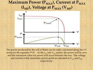
- 8. Maximum Power (PMAX), Current at PMAX (IMP), Voltage at PMAX (VMP) The power produced by the cell in Watts can be easily calculated along the I-V sweep by the equation P=IV. At the ISC and VOC points, the power will be zero and the maximum value for power will occur between the two. The voltage and current at this maximum power point are denoted as VMP and IMP respectively.
- 9. Fill Factor The Fill Factor (FF) is essentially a measure of quality of the solar cell. It is calculated by comparing the maximum power to the theoretical power (PT) that would be output at both the open circuit voltage and short circuit current together.
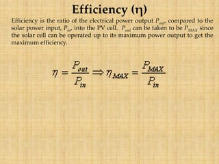
- 10. Efficiency (╬Ę) Efficiency is the ratio of the electrical power output Pout, compared to the solar power input, Pin, into the PV cell. Pout can be taken to be PMAX since the solar cell can be operated up to its maximum power output to get the maximum efficiency.
- 11. Temperature Measurement Consideration When a PV cell is exposed to higher temperatures, ISC increases slightly, while VOC decreases more significantly. Temperature Effect on I-V Curve
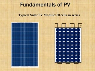
- 12. Fundamentals of PV Typical Solar PV Module: 60 cells in series
- 13. PV Fundamentals: The Solar Module But what if we shaded one cell?
- 14. PV Fundamentals: The Solar Module 0V Due to the series connection, no current can flow through the module, so it cannot produce any power!
- 15. PV Fundamentals: The Solar Module 0V Furthermore, there is a reverse bias across the shaded cell due to the voltages produced by the other cellsŌĆ” -44*0.6 = -26.4V +15*0.6 = +9V
- 16. PV Fundamentals: The Solar Module 0V -44*0.6 = -26.4V +15*0.6 = +9V Voltage Across Shaded Cell = -35.4V (Reverse Bias)
- 17. PV Fundamentals: The Solar Module 0V -44*0.6 = -26.4V +15*0.6 = +9V Voltage Across Shaded Cell = -35.4V (Reverse Bias) Multi-crystalline Solar Cell Reverse Bias Breakdown Voltage: -13V
- 18. PV Fundamentals: The Solar Module 0V -44*0.6 = -26.4V +15*0.6 = +9V Voltage Across Shaded Cell = -35.4V (Reverse Bias) Multi-crystalline Solar Cell Reverse Bias Breakdown Voltage: -13V Result: Cell over heats and is damaged (hot spot)!!
- 19. PV Fundamentals: The Solar Module SolutionŌĆ”
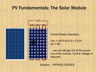
- 20. PV Fundamentals: The Solar Module Maximum Reverse Bias: 19*0.6 = 11.4V (OK!) SolutionŌĆ” BYPASS DIODES
- 21. PV Fundamentals: The Solar Module Normal Operation: Voc = 60*0.6 = 36V Isc = 8A SolutionŌĆ” BYPASS DIODES
- 22. PV Fundamentals: The Solar Module Partial Shade Operation: Voc = (40*0.6)-0.5 = 23.5V Isc = 8A ŌĆ”we can still get 2/3 of the power out of the module, but the voltage is reduced. SolutionŌĆ” BYPASS DIODES
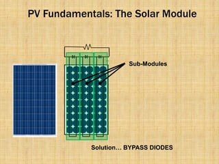
- 23. PV Fundamentals: The Solar Module Sub-Modules SolutionŌĆ” BYPASS DIODES
- 24. Shading : Solutions (Cont.) Micro-inverters + String of n Modules in Series Voc = n*36V Where ŌĆśnŌĆÖ is the number of modules
- 25. PV Fundamentals: The Solar Array _ + Voc = n*36V String of n Modules in Series Isc = m*8A m Strings In Parallel String of n Modules in Series String of n Modules in Series
- 26. PV Fundamentals: The Solar Array _ + Voc = n*36V String of n Modules in Series Isc = m*8A Inverter m Strings In Parallel String of n Modules in Series AC Ou Varies the load on the array to operate at the Maximum String of n Modules in Series Power Point (MPP)