SolidWorks Assemblies
- 1. Force Design SolidWorks Assemblies
- 2. Performance Options Automatically load Lightweight Always Resolve sub-assemblies
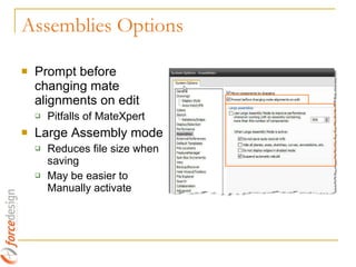
- 3. Assemblies Options Prompt before changing mate alignments on edit Pitfalls of MateXpert Large Assembly mode Reduces file size when saving May be easier to Manually activate
- 4. Things to Do…Always Minimize mates and components in top level assembly Resolve Warnings and especially Errors Each rebuild SolidWorks tries to resolve the problem
- 5. Top Down Design What’s Good Components Interrelated External Relations Changes Propagate Design intent more explicit… What’s Bad Lots of External References More difficult file management Decreased Performance Sloppier design Insert New Part Parts not orientated well MAYBE
- 6. What’s Good Easier to control Model, Diagnose Problems Fewer External References Easier File Management Better Performance Works Better with PDM What’s Bad Design Intent not as clear… More “Manual” Not as Quick & Easy Or Bottom Up MAYBE
- 7. So Which is It? Top Down or Bottom Up? Reasoning to Support either Method Each has its Place Neither is Right or Wrong Combination of each Method Recommend Starting with Bottom Up and adding External References
- 8. Planes & Axis Establish a “Datum” or important location such as a Locating Pin, Axis of a Shaft etc. Place the Locating Pin at the Origin Create Planes and Axis at other Critical locations with External References Centered and Balanced
- 9. Mates Start with one Fixed component Automatically Suppresses mates (f) Mate each component to only one component 3 Mates Preferred Two Opinions on Cylindrical components 1) Eliminate all Degrees of Freedom 2) Minimize Mates You Decide! Use Reference Geometry Macros to Speed Mating
- 10. Where are they for Assemblies? Workaround Create a Patterned Feature in a Component Hole Wizard Feature with Multiple Holes Or Pattern Bodies (Surface or Solids) Insert the component Pattern Assembly Component(s) using Feature Driven Pattern Example Using Solid Bodies Sketch Driven Patterns
- 11. Product Files Imported Geometry Subject to Change during Design Build assembly around Product Use Reference Geometry for Mating ‘ Master’ Assembly allows quick change to revised parts
- 12. Managing External References External References are wonderful, But… Can get Out of Control Increase Rebuild time There are Bugs….WHAT?!? Revealing the Bugs
- 13. Questions/Discussion Layouts Configurations Display States Assembly Features Belts/Chains
- 14. Thank You
Editor's Notes
- #6: Model a pulley system as an example
- #8: Discuss this, maybe ask questions of crowd
- #9: Show example
- #12: 1) Show reference geometry in a large product, 2) Create a few references 3) Build assembly Using the product 4) Replace product
- #13: Example: Red Block assembly 1) Start with GreenAssy.sldasm, contains Green block & Drawing 2) Open Dialog, Copy/Paste assembly and drawing 3) Select “Copy of GreenAssy.slddrw” and change references to “copy of assy.sldasm” 4) Open copied drawing 5) Open assembly from view (IMPORTANT). “Copy of Assy.sldasm” opens 6) Note that external Ref’s have changed for the Green Block
- #15: Show 狠狠撸s


