Solidworks PCB Presentation
- 2. 3Č┘│¦.░õ░┐▓č/│¦░┐│ó▒§Č┘░┬░┐Ėķ░Ł│¦┬®Č┘▓╣▓§▓§▓╣│▄▒¶│┘│¦▓Ō▓§│┘├©│Š▒▓§┤ź░õ┤Ū▓į┤┌Š▒╗Õ▒▓į│┘Š▒▓╣▒¶▒§▓į┤┌┤Ū░∙│Š▓╣│┘Š▒┤Ū▓į┤ź8/3/2016┤ź░∙▒┤┌.:3Č┘│¦│ÕČ┘┤Ū│”│▄│Š▒▓į│┘│Õ2012 1 SOLIDWORKS PCB, kas tai? 2 Esminiai privalumai 3 Nauda vartotojui 4 Demonstracija Turinys Image courtesy of: BPG, Inc 4 Klausimai
- 4. 3Č┘│¦.░õ░┐▓č/│¦░┐│ó▒§Č┘░┬░┐Ėķ░Ł│¦┬®Č┘▓╣▓§▓§▓╣│▄▒¶│┘│¦▓Ō▓§│┘├©│Š▒▓§┤ź░õ┤Ū▓į┤┌Š▒╗Õ▒▓į│┘Š▒▓╣▒¶▒§▓į┤┌┤Ū░∙│Š▓╣│┘Š▒┤Ū▓į┤ź8/3/2016┤ź░∙▒┤┌.:3Č┘│¦│ÕČ┘┤Ū│”│▄│Š▒▓į│┘│Õ2012 ECAD ir MCAD Bendradarbiavimo I┼Ī┼Ī┼½kiai Vienas skyrius vadovauja kitam Projektavimo ─»ranki┼│ lankstumo tr┼½kumai Dingstantys duomenys Bendros projekto visumos i┼Īlaikymas Dabartiniai ─»rankiai ┼Īios problemos i┼Ī esm─Śs nesprend┼Šia ! Rinkai reikia i┼Īmani┼│ produkt┼│ !
- 5. 3Č┘│¦.░õ░┐▓č/│¦░┐│ó▒§Č┘░┬░┐Ėķ░Ł│¦┬®Č┘▓╣▓§▓§▓╣│▄▒¶│┘│¦▓Ō▓§│┘├©│Š▒▓§┤ź░õ┤Ū▓į┤┌Š▒╗Õ▒▓į│┘Š▒▓╣▒¶▒§▓į┤┌┤Ū░∙│Š▓╣│┘Š▒┤Ū▓į┤ź8/3/2016┤ź░∙▒┤┌.:3Č┘│¦│ÕČ┘┤Ū│”│▄│Š▒▓į│┘│Õ2014 Naujos projektavimo galimyb─Śs SOLIDWORKS PCB, Kas Tai? Nauja, savaranki┼Īka PCB projektavimo sistema
- 6. 6 3DS.COM┬®DassaultSyst├©mes|ConfidentialInformation|8/3/2016|ref.:3DS_Document_2016 SOLIDWORKS PCB, Kas Tai? Connector
- 7. 7 ŌĆó Projektavimo SistemaŌĆō SOLIDWORKS PCB` ŌĆó Bendradarbiavimo PriedasŌĆō SOLIDWORKS PCB CONNNECTOR ŌĆó Geriausias produktas i┼Īmaniam projektavimui ir produktams ŌĆó Ambicinga sistema apjungianti esamus SOLIDWORKS sprendimus ŌĆó S─ģsaja su SOLDWORKS Electrical ŌĆó S─ģsaja su SOLIDWORKS ECO SYSTEM ŌĆó Simuliacijos galimyb─Śs elektronikos ir mechanikos erdv─Śse ŌĆó Pripa┼Šintas stambiausi┼│ SOLIDWORKS vartotoj┼│ Connector
- 8. 8 ’ā╝ Naudojama gerai ┼Šinoma Altium technologija ’ā╝ Neprilygstama ECAD-MCAD integracija ’ā╝ Patogi vartotojo s─ģsaja ’ā╝ S─ģsaja su tiek─Śj┼│ informacija esamu laiku ’ā╝ Nepertraukiama s─ģsaja su principine schema, plok┼Īte, jos 3D atvaizdu ’ā╝ SOLIDWORKS fail┼│ perk─Ślimas ─» elektronikos aplink─ģ SOLIDWORKS PCB: SAVARANKI┼ĀKA SPAUSDINTINI┼▓ PLOK┼Ā─īI┼▓ PROJEKTAVIMO SISTEMA SOLIDWORKS PCB CONNECTOR : PRIEDAS ALTIUM DESIGNER PROGRAMAI LEID┼ĮIA NAUDOTI SOLIDWORKS PCB BENDRADARBIAVIMO TECHNOLOGIJAI Esminiai Privalumai
- 9. 9 Automatizuota klaid┼│ patikra S─ģsaja su tiek─Śjais esamu laiku Esminiai Privalumai
- 10. 10 S─ģsaja tarp principin─Śs schemos ir plok┼Īt─Śs SOLIDWORKS modeli┼│ integracija elektronikos aplinkoje Vartotojo s─ģsaja perteikia SOLIDWORKS patogum─ģ Esminiai Privalumai
- 11. 11 3D atvaizdavimo galimyb─Śs Principin─Śs schemos Efektyvus 2D plok┼Īt─Śs atvaizdavimas kolaboracija su SOLIDWORKS SOLIDWORKS Electrical integracija SOLIDWORKS Ecosystem Galimyb─Śs Esminiai Privalumai
- 12. 12 Lyderiaujan─Źios rinkos sistemos Geriausias bendradarbiavimas tarp ECAD ir MCAD aplink┼│ visoje rinkoje Esminiai Privalumai
- 14. 14 SOLIDWORKS PCB SOLIDWORKS Electrical SOLIDWORKS Electrical 3D SOLIDWORKS Neprilygstama Integracija su SOLIDWORKS Electrical ir 3D Nauda Vartotojui
- 15. 3Č┘│¦.░õ░┐▓č/│¦░┐│ó▒§Č┘░┬░┐Ėķ░Ł│¦┬®Č┘▓╣▓§▓§▓╣│▄▒¶│┘│¦▓Ō▓§│┘├©│Š▒▓§┤ź░õ┤Ū▓į┤┌Š▒╗Õ▒▓į│┘Š▒▓╣▒¶▒§▓į┤┌┤Ū░∙│Š▓╣│┘Š▒┤Ū▓į┤ź8/3/2016┤ź░∙▒┤┌.:3Č┘│¦│ÕČ┘┤Ū│”│▄│Š▒▓į│┘│Õ2014 Klaid┼│ taisymas ankstyvosiose projekto stadijose Nauda Vartotojui ŌĆó Ankstyvos klaidos- ma┼Ši pakeitim┼│ ka┼Ītai ŌĆó V─Ślyvos klaidos- dideli pakeitim┼│ ka┼Ītai Klaid┼│ taisymas
- 16. 3Č┘│¦.░õ░┐▓č/│¦░┐│ó▒§Č┘░┬░┐Ėķ░Ł│¦┬®Č┘▓╣▓§▓§▓╣│▄▒¶│┘│¦▓Ō▓§│┘├©│Š▒▓§┤ź░õ┤Ū▓į┤┌Š▒╗Õ▒▓į│┘Š▒▓╣▒¶▒§▓į┤┌┤Ū░∙│Š▓╣│┘Š▒┤Ū▓į┤ź8/3/2016┤ź░∙▒┤┌.:3Č┘│¦│ÕČ┘┤Ū│”│▄│Š▒▓į│┘│Õ2014 Patogiausia sistema su vietiniu palaikymu Nauda Vartotojui Paprasta naudoti Kolaboracijos galimyb─Śs Vietinis palaikymas Kiti pana┼Ī┼½s produktai
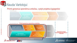
- 17. 3Č┘│¦.░õ░┐▓č/│¦░┐│ó▒§Č┘░┬░┐Ėķ░Ł│¦┬®Č┘▓╣▓§▓§▓╣│▄▒¶│┘│¦▓Ō▓§│┘├©│Š▒▓§┤ź░õ┤Ū▓į┤┌Š▒╗Õ▒▓į│┘Š▒▓╣▒¶▒§▓į┤┌┤Ū░∙│Š▓╣│┘Š▒┤Ū▓į┤ź8/3/2016┤ź░∙▒┤┌.:3Č┘│¦│ÕČ┘┤Ū│”│▄│Š▒▓į│┘│Õ2012 Nauda Vartotojui Priimti geresnius sprendimus anks─Źiau, vystyti projektus lygiagre─Źiai Projekto / gaminio duomen┼│ valdymas Gamyba Gaminio simuliacija Galutines dokumentacijos derinimas, paruo┼Īimas Informacijos suderinimas, Integracija Tipinis procesas 3D mechaninis 3D dalies projektavimas Galutin─Śs dokumentacijos derinimas, paruo┼Īimas Gamyba Principin─Śs schemos ir plok┼Īt─Śs projektavimas SOLIDWORKS si┼½lo Sutaupyti pinigai, resursai Priimti geresnius sprendimus anks─Źiau 3D mechaninis 3D dalies projektavimas Pasiruo┼Īimas gamybai Informacijos suderinimas, Integracija, klaid┼│ taisymas Pasiruo┼Īimas gamybai Principin─Śs schemos ir plok┼Īt─Śs projektavimas
- 18. 3Č┘│¦.░õ░┐▓č/│¦░┐│ó▒§Č┘░┬░┐Ėķ░Ł│¦┬®Č┘▓╣▓§▓§▓╣│▄▒¶│┘│¦▓Ō▓§│┘├©│Š▒▓§┤ź░õ┤Ū▓į┤┌Š▒╗Õ▒▓į│┘Š▒▓╣▒¶▒§▓į┤┌┤Ū░∙│Š▓╣│┘Š▒┤Ū▓į┤ź8/3/2016┤ź░∙▒┤┌.:3Č┘│¦│ÕČ┘┤Ū│”│▄│Š▒▓į│┘│Õ2014 ECAD ir MCAD Bendradarbiavimo Sprendimai ŌĆó Lygiagretus atskir┼│ skyri┼│ darbas ŌĆó Lankstus projektavimo ─»rankis ŌĆó Perkeliami duomenys ŌĆó Vientisa SOLIDWORKS aplinka ŌĆó Laiku ir efektyviai pateikiami sprendimai!
Editor's Notes
- #3: ║▌║▌▀Ż Message : Tell the audience what you will cover and refer back to it in closing your presentation Speaker Notes : Today we will cover four things : 1. Who we are ŌĆō a little about the company 2. What we do ŌĆō our products and what we bring to the table 3. We will talk a little about some of our customers and their successes 4. But MOST importantly, we will talk about how we can help YOU meet your business goals. After all, thatŌĆÖs why we are here!
- #5: ║▌║▌▀Ż Message : SolidWorks CAD tools are the result of 20 years of development and the feedback of over two million users. Our rock-solid software helps you get your job done faster and easier, no matter what industry you work in. Main Points: Using SolidWorks is the fastest and easiest way to create production-ready designs Industrial designers can use SolidWorks to create stunning product concepts using freeform surfacing and reverse engineering Design engineers use SolidWorks to add function to the form Manufacturing engineers use SolidWorks to create molds, dies, jigs and fixtures that reference the product geometry Speaker Notes: SolidWorks Mechanical CAD, our core product, has proven itselfŌĆöthrough its intuitive user experienceŌĆöto be up to the challenge of any industry. We know that many of you currently employ a 2D-based design approach, and we have a rich set of tools to re-use that data, and a full suite of capabilities for you to create the production documentation that you need. SolidWorks provides the tools you need to be more productive and get your products to market faster. ┬Ā In addition to a host of modelling and assembly design tools for sheet metal, surfaces and solids, we have additional tools to help communicate your designs, including eDrawings, which you will see in a few moments in the product demonstration. The new costing tool helps designers make faster and more repeatable decisions based on manufacturing costs and helps manufacturers automate their quoting processes. ┬Ā These tools allow you to share your designs with your partners, subcontractors and colleagues in smart new ways, all so you can improve knowledge transfer and shorten the design cycle.
- #10: To ensure the design is done right the first time Solidworks PCB incorporates a wide-ranging and customizable deign rule checks that keep your schematic and PCB layout error free through out the design process Making informed decisions when selecting new components is vital to ensure cost and to minimize supply chain interruptions Solidworks PCB incorporates Real time supplier data, making it incredibly simple and stress-free to locate and select new components that are not part of your existing component library
- #11: Solidworks PCB has the all the power to meet todays electronic design demands. As you can see Solidworks PCB has a Solidworks inspired Interface, making simple and easy to learn Lets watch the interactive routing capabilities Manual push and shove , workaround, push obstacle Modes as well as an Interactive AutoRoute mode that intelligently select the best routing technology based you design. And for More complex designs multi-track and Differential pair routing modes are also available. One of the most innovative feature that SOLIDWORKS PCB is the ability to incorporate SOLIDWORKS models with in the PCB Design environment, design intent without the need to change tools. a powerful 3d collision engine with real time highlight capabilities makes simple and easy to find interference and fit problems. This powerful 3D technology ensures that the design are done right the first time. The exclusive capability to produce SOLIDWORKS models which can include design feature such as viaŌĆÖs, traces and planes, make it easy to work with other SOLIDDWORKS products such as ELECTRONICS Cooling and flow Simulation.
- #12: SOLIDWORKS PCB tools SCHMATIC capture tool For Electrical Design Traditional PCB layout tool For PCB design 3D visualized layout For 3d product visualization and review Solidworks Mechanical \ PCB Collaboration Add in for Solidworks that makes the magic happen Solidworks electrical integration Direct interface providing a End to End Electrical Solution, electronic, electrical and mechanical 3D ŌĆō true 3D electrical Technology deployment SOLIDWORKS PCB PRODUTS ARE Solidworks Ecosystem Ready
- #13: Lets face it Being comfortable with the design tools and processes you already use is the best way to get job done This is why in SOLIDWORKS PCB we employ on demand collaboration, allowing the mechanical and Electrical designers work in parallel Changes are stress free and through easy to use collaborative interface. Lets watch as the mechanical designer ŌĆ”. Explain Eliminating the need for manual file and data exchange and ensuring that the design are synchronized !
- #14: Intro: as they say back in ŌĆ£BostonŌĆØ it is wicked awesome to be here today to present this incredible innovative technology ŌĆ£ Solidworks PCBŌĆØ Built on over 50 year of combined experience in delivering best in class solutions to their customers SOLIDWORKS PCB combines the ELECTRONICS design expertise of Altium with Solidworks technologies to create the tightest integrated Electro-mechanical solution in the industry. Seamlessly synchronize between electronic design and mechanical design on demand without compromising on technology or product design works flow. The SOLIDWORKS inspired interface of SOLIDWORKS PCB provides a unified interface between schematic design and PCB layout simplifying the electronics design process. This innovative technology extends into the SOLIDWORKS ECO-SYSTEM providing an end to end design solutions that include Electrical, Mechanical, simulation and data management. I would also like to introduce SOLIDWORKS PCB Connector. This revolutionary product allows current and future uses of ALTIUM design products to preserve and enhance their investments with the innovative capabilities found in SOLDWORKS PCB.
- #18: Solve new problems What is our approach from process perspective? Change the engineering and design process to work in parallel instead of serial Why:? Make better business decisions, earlier Create better designs
- #19: ║▌║▌▀Ż Message : SolidWorks CAD tools are the result of 20 years of development and the feedback of over two million users. Our rock-solid software helps you get your job done faster and easier, no matter what industry you work in. Main Points: Using SolidWorks is the fastest and easiest way to create production-ready designs Industrial designers can use SolidWorks to create stunning product concepts using freeform surfacing and reverse engineering Design engineers use SolidWorks to add function to the form Manufacturing engineers use SolidWorks to create molds, dies, jigs and fixtures that reference the product geometry Speaker Notes: SolidWorks Mechanical CAD, our core product, has proven itselfŌĆöthrough its intuitive user experienceŌĆöto be up to the challenge of any industry. We know that many of you currently employ a 2D-based design approach, and we have a rich set of tools to re-use that data, and a full suite of capabilities for you to create the production documentation that you need. SolidWorks provides the tools you need to be more productive and get your products to market faster. ┬Ā In addition to a host of modelling and assembly design tools for sheet metal, surfaces and solids, we have additional tools to help communicate your designs, including eDrawings, which you will see in a few moments in the product demonstration. The new costing tool helps designers make faster and more repeatable decisions based on manufacturing costs and helps manufacturers automate their quoting processes. ┬Ā These tools allow you to share your designs with your partners, subcontractors and colleagues in smart new ways, all so you can improve knowledge transfer and shorten the design cycle.


