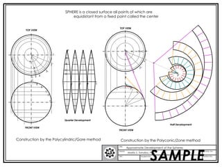
The document describes two methods for approximately developing a sphere:
1. The polycylindric/gore method which divides a quadrant into equal central angles and measures arcs and chords to form gores which are assembled to approximate the sphere.
2. The polyconic/zone method which draws concentric circles and arcs, dividing the sphere into equal sectors. Tangent lines and arcs are drawn to form zones which are assembled to approximate the sphere.
Section of solids - ENGINEERING DRAWING/GRAPHICSAbhishek Kandare
油
Section of solids
THIS SLIDE CONTAINS WHOLE SYLLABUS OF ENGINEERING DRAWING/GRAPHICS. IT IS THE MOST SIMPLE AND INTERACTIVE WAY TO LEARN ENGINEERING DRAWING.SYLLABUS IS RELATED TO rajiv gandhi proudyogiki vishwavidyalaya / rajiv gandhi TECHNICAL UNIVERSITY ,BHOPAL.
1. When two solids intersect, their surfaces meet along a curve called the curve of intersection. This curve is common to both solids.
2. Curves of intersection show the exact maximum surface contact between two solids, which is important for making strong, leak-proof joints when solids are joined together.
3. The document provides examples of determining the curve of intersection for various solids penetrating each other, such as cylinders, prisms, and cones. The method involves drawing three views and transferring points of intersection between views.
Development of surfaces of solids -ENGINEERING DRAWING - RGPV,BHOPALAbhishek Kandare
油
Development of surfaces of solids
THIS SLIDE CONTAINS WHOLE SYLLABUS OF ENGINEERING DRAWING/GRAPHICS. IT IS THE MOST SIMPLE AND INTERACTIVE WAY TO LEARN ENGINEERING DRAWING.SYLLABUS IS RELATED TO rajiv gandhi proudyogiki vishwavidyalaya / rajiv gandhi TECHNICAL UNIVERSITY ,BHOPAL.
The document describes different methods for drawing ellipses, parabolas, and hyperbolas which are known as conic sections. These curves are formed by cutting a cone with planes. Ellipses can be drawn using the concentric circle method, rectangle method, oblong method, arcs of circle method, and rhombus method. Examples are given demonstrating how to draw ellipses using each of these techniques. Parabolas and hyperbolas are also defined and their eccentricities described. Methods for drawing tangents and normals to these curves are also mentioned.
The document lists AutoCAD 2D and 3D commands with their short keys. It contains 59 2D commands such as line, rectangle, fillet, trim, move, copy, dimension, text and their short keys. It also lists 8 3D commands including extrude, region, subtract, union, revolve, slice, intersect and their associated toolbars. The document was prepared by Muhammad Imran Khan from Apex Educator.
This document provides information about isometric projections and how to draw them. It defines key terms like isometric axes, lines, and planes. It explains that in isometric projections, all three dimensions are shown at equal inclinations of 120 degrees. It provides examples of how to draw isometric views of various objects like prisms, pyramids, cylinders, and their combinations. It also describes how to construct an isometric scale to accurately draw dimensions when creating isometric projections.
A document discusses engineering applications of projections and sections of solids. It defines different types of section planes including principal planes (HP and VP) and auxiliary planes like auxiliary vertical plane (AVP), auxiliary inclined plane (AIP), and profile plane (PP). An AVP cuts the top view of a solid as a straight line, while an AIP cuts the front view as a straight line. Properties of section lines and conventions for showing the cutting plane and removed part are also described. Several example problems are provided to illustrate drawing different views and true shapes of sections for various solids cut by various section planes.
The document discusses architectural concepts and how they are developed and expressed. It defines a concept as an idea or thought that provides identity and direction for a project. Concepts can come from a site, program, culture or influences. They should provide an exterior expression and interior experience. Concepts are expressed through diagrams, models, analogy, and metaphor to convey relationships and ideas. Developing a strong concept gives depth and meaning to a design.
This document describes site approaches and building entrances. It discusses different types of site approaches including frontal, oblique, and spiral approaches and how they prolong the sequence of approaching a building. It also categorizes building entrances as flush, recessed, or projected and provides examples of each. The document emphasizes that entrances should be identifiable, usable, and provide shelter and lighting.
The document discusses the intersection of solids and curves of intersection. It provides examples of different solids intersecting, like cylinders, cones, and prisms. It explains that curves of intersection show the maximum surface contact between intersecting solids. Steps are provided to draw the projections and curves of intersection for different examples, like a cylinder penetrated by another cylinder, or a square prism penetrated by a cylinder. Real-world examples are shown like machine components or industrial equipment.
introduction of engineering graphics ,projection of points,lines,planes,solids,section of solids,development of surfaces,isometric projection,perspective projection
Download the original presentation for animation and clear understanding. This Presentation describes the concepts of Engineering Drawing of VTU Syllabus. However same can also be used for learning drawing concepts. Please write to me for suggestions and criticisms here: hareeshang@gmail.com or visit this website for more details: www.hareeshang.wikifoundry.com.
This document discusses a new project involving the use of artificial intelligence and machine learning techniques to analyze large datasets and provide insights. The project aims to develop models that can process information and identify key patterns and relationships in an automated fashion to help organizations make better data-driven decisions. A multidisciplinary team of engineers, data scientists and domain experts will work together on this initiative over the next year.
Section of solids, Computer Aided Machine Drawing (CAMD) of VTU Syllabus prepared by Hareesha N Gowda, Asst. Prof, Dayananda Sagar College of Engg, Blore. Please write to hareeshang@gmail.com for suggestions and criticisms.
Light gauge steel framing is a non-combustible alternative to light wood framing that is dimensionally and nominally equivalent. It is made from cold-formed sheet steel that is bent into C-shapes and runner channels with pre-punched holes. It must be braced using channels and straps until sheathing is attached, as the members can easily twist and bend. It provides an equivalent to light wood framing for studs, joists, and other framing elements while saving on trees.
El documento presenta los planos y detalles constructivos de la Casa Farnsworth dise単ada por Mies van der Rohe en Plano, Illinois entre 1946-1950. Incluye informaci坦n sobre el emplazamiento, planta baja, alzados este y oeste, secci坦n A y detalles constructivos. La casa tiene una superficie de 206 metros cuadrados y est叩 construida sobre pilotes de acero con muros de vidrio y piso de travertino.
Diagrid Structures: Introduction & Literature SurveyUday Mathe
油
This document provides an overview of diagrid structural systems. Some key points:
- Diagrids consist of a rigid core surrounded by a grid of diagonal bracing members that provide structural stability and resistance to lateral forces. This eliminates the need for most vertical columns.
- Diagrids can carry both gravity and lateral loads through axial action of the diagonal members. They provide bending and shear rigidity and behave like a 3D box resisting compression and tension.
- Optimal design of diagrids involves determining the ideal angle of the diagonal members (around 35-75 degrees) and allocating stiffness to maximize lateral rigidity. Methods include using partial differential equations, topology optimization, and stiffness-based methodology.
This document discusses various types of engineering curves used in design. It begins by explaining why curves are important in fields like civil, mechanical, electronics and computer engineering for applications such as bridges, gears, satellites, and computer graphics. It then defines and provides examples of common curves including conic sections (circles, ellipses, parabolas, hyperbolas), cycloids, involutes, spirals, and helices. Specific problems are presented demonstrating how to construct some of these curves geometrically by defining parameters and drawing the loci of moving points. Examples of real-world applications are also provided for each curve type.
1. The document discusses section drawings and how they are used in working drawings to convey construction details and interior spaces of buildings.
2. Key details shown in section drawings for working drawings include building materials, dimensions, structural systems, finishes, and mechanical/electrical elements.
3. Different types of sections are described like structural sections and wall sections, along with considerations for locating the section plane.
This document provides information about isometric drawings and projections. It begins by explaining that 3D drawings can be drawn in various ways, including isometrically where the three axes are equally inclined at 120 degrees. It then discusses the construction of isometric scales and various techniques for drawing isometric views of plane figures, solids, and assemblies of objects. Examples are provided to illustrate how to draw isometric views when given orthographic projections of an object. The purpose of isometric drawings is to show the overall size, shape, and appearance of an object prior to production.
The Centre Georges Pompidou in Paris, France was designed by architects Richard Rogers and Renzo Piano. They won the competition to design the building in 1977 despite not being famous architects at the time. The building features a colour-coded exterior displaying its functional mechanical systems. It has an open floor plan interior and a large glass and steel superstructure supported by a reinforced concrete structure.
Intersection OF SOLIDES
THIS SLIDE CONTAINS WHOLE SYLLABUS OF ENGINEERING DRAWING/GRAPHICS. IT IS THE MOST SIMPLE AND INTERACTIVE WAY TO LEARN ENGINEERING DRAWING.SYLLABUS IS RELATED TO rajiv gandhi proudyogiki vishwavidyalaya / rajiv gandhi TECHNICAL UNIVERSITY ,BHOPAL.
Scales
THIS SLIDE CONTAINS WHOLE SYLLABUS OF ENGINEERING DRAWING/GRAPHICS. IT IS THE MOST SIMPLE AND INTERACTIVE WAY TO LEARN ENGINEERING DRAWING.SYLLABUS IS RELATED TO rajiv gandhi proudyogiki vishwavidyalaya / rajiv gandhi TECHNICAL UNIVERSITY ,BHOPAL.
The document discusses architectural drawings and their purpose and components. Architectural drawings are used by architects to design buildings and communicate designs to clients and contractors. They include floor plans, site plans, elevations, sections, and detail drawings. Important architects mentioned include Imhotep, who designed the step pyramid of Djoser in ancient Egypt, and Le Corbusier, a pioneer of modern urban planning.
This document discusses the design of flat slab structures. It begins by defining a flat slab as a type of slab supported directly on columns without beams. It then provides details on the types of flat slabs, their common uses in buildings, and benefits such as flexibility in layout and reduced construction time. The document goes on to discuss key design considerations for flat slabs including thickness, drops, column heads, and methods of analysis. It focuses on the direct design method and provides limitations for its use.
This presentation summarizes the work of contemporary architect Shigeru Ban. It discusses his biography, theoretical foundations, principles of using simple and ecological materials. It highlights several of his notable projects such as the Japan Pavilion at Expo 2000 and the Pompidou Center in Metz. The presentation concludes that Ban uses inexpensive, available materials to create luxurious buildings and sees architectural difficulties as opportunities for innovation.
The document discusses different map projections that can be used to map the sphere to the plane. It begins by explaining that some distortion is inevitable when mapping a spherical surface to a flat plane. It then presents two central map projections - the gnomonic projection and the stereographic projection. For each projection, it analyzes the distortion by examining how a small disk at various points on the sphere is mapped to an ellipse. This ellipse, called the distortion ellipse, provides a way to visualize and compare the distortion across different regions and between different map projections.
The document discusses sections and developments of solids. It defines sectioning a solid as cutting it with an imaginary cutting plane to understand its internal details. The cutting plane is called the section plane. It provides examples of typical section planes and resulting shapes for different solids. Developments are defined as unfolding the hollow sheet metal version of a solid completely, resulting in its unfolded 2D shape. Developments are useful for manufacturing complex objects. The document includes illustrations and examples of sectioning various solids like prisms, cylinders, cones, pyramids and finding their true shapes and developments.
Este documento presenta una introducci坦n a la geometr鱈a del espacio, incluyendo definiciones de figuras geom辿tricas tridimensionales como la esfera. Explica que la geometr鱈a del espacio estudia las propiedades y medidas de estas figuras. Luego, proporciona detalles sobre la historia, definici坦n, elementos y teoremas relacionados con la esfera.
Este documento presenta informaci坦n sobre la esfera, incluyendo su concepto, partes, elementos, f坦rmulas y una conclusi坦n. Explica que una esfera es un cuerpo geom辿trico limitado por una superficie curva cuyos puntos est叩n a igual distancia de un punto interior llamado centro. Detalla las partes de una esfera como el centro, radio, di叩metro y polos, as鱈 como elementos como hemisferios, semiesferas, husos esf辿ricos y casquetes esf辿ricos. Finalmente, ofrece f坦rmulas para calcular el
The document provides instructions for drawing the front elevation of a cylinder with the following specifications:
1) The diameter (d) is 3 inches and the height (h) is 3.5 inches.
2) The angle (A) is 22.5 degrees.
3) It describes drawing center lines, horizontal and vertical lines, and using a protractor to draw the angle.
4) It then provides steps to draw arcs using a compass to complete the cylinder shape.
This document provides examples and instructions for developing the surfaces of various solids using the radial line method. It begins with an overview of developing a square pyramid by opening up the triangular faces and drawing them as separate triangles connected by the base square. Several examples are then given of developing specific solids like pyramids, cones, and funnels that have been cut by various planes. Guidance is provided on drawing the projections, marking new points where edges intersect the cutting plane, and using radial lines to accurately trace the remaining portions on development. Tips are also included to first sketch the development lightly and then project and darken remaining sections.
The document discusses the projection of solids and provides examples of how to project solids in different positions. It describes how to project solids when the axis is perpendicular to or parallel to the horizontal and vertical planes. It also explains how to project solids when the axis is inclined to one of the planes. Examples are provided for projecting prisms, pyramids, cylinders and cones in various positions.
A cylinder and square prism intersect with their axes bisecting each other. To find the curves of intersection:
1. Draw lines on the surface of one solid and transfer points of intersection to corresponding positions on the other views.
2. When one solid completely penetrates another, there will be two curves of intersection.
3. Maximum surface contact between intersecting solids provides the strongest and most leak-proof joint.
The document discusses sections and developments of solids. It defines sectioning a solid as cutting it with an imaginary cutting plane to understand its internal details. The cutting plane is called the section plane. It shows how to draw the true shape of a section and the development of the remaining solid. It provides examples of typical section planes and shapes formed for different solids. It also defines development as the shape of an unfolded sheet representing the lateral surfaces of a hollow solid. Examples of its engineering applications are given. The document concludes with problems demonstrating how to draw sections, true shapes and developments of various solids.
The cerebral hemispheres develop from the telencephalon, which consists of a median part and two lateral diverticula. These diverticula are the primordia of the hemispheres. As the hemispheres expand, their walls thicken and cover other brain structures. Various structures develop within the hemispheres, including the corpus striatum, hippocampus, internal and external capsules, and cerebral cortex. The lateral ventricles develop from cavities within the telencephalon diverticula.
R. Buckminster Fuller dedicated his life to solving global problems through comprehensive design. He is known for developing the geodesic dome, a strong spherical structure made of triangles that uses minimal materials. Fuller worked across many fields and influenced generations with his principle of "doing more with less." He designed dome structures, houses like the Dymaxion house and Wichita house, that were efficient, low-cost and focused on sustainability.
The document describes how ancient mathematicians derived the formula for the area of a circle by cutting a circle into pieces and rearranging them to form a rectangle. They determined that the height of the rectangle is equal to the radius of the circle, and the base is equal to half the circumference. Substituting these relationships into the area formula for a rectangle produces the area of a circle formula: A = r2.
1) Aboriginal people are the indigenous people of Australia who tell stories called Dreamings about how the world began using symbols in art.
2) Aboriginal art comes from Australia and uses natural earth colors like black, yellow, red, and white as well as dots to represent natural elements and was created using fingers or sticks without brushes from materials found in the desert environment.
3) Traditional aboriginal music uses rhythmic singing accompanied by percussive instruments like clapsticks or body slapping as well as the didgeridoo.
R. Buckminster Fuller was an American architect and engineer known for developing the geodesic dome. He was also a philosopher who had unconventional ideas. He attended Harvard but was expelled twice. For decades, Fuller developed many designs focused on efficiency and lower costs, documenting his work daily. His most famous structure is the geodesic dome, a spherical structure based on triangles that distributes stress evenly. Fuller designed dome-shaped structures like the Biosphere museum in Montreal and Dymaxion houses, which sought to use minimal materials efficiently. However, none of his house designs were widely produced. Fuller received patents for his dome design and popularized its use in buildings.
Aboriginal art originated around 40,000-50,000 years ago when Aboriginal people first settled in Australia. They told stories through paintings using natural pigments, often on bark canvases. Common symbols in Aboriginal art represent animals, plants, people and Dreamtime stories. Dot painting involves applying colored dots in patterns using fingers, sticks or brushes. The dots make designs that reflect Aboriginal culture, rituals, and connection to the land. Aboriginal art is deeply meaningful and an important part of Australia's cultural heritage.
Atmospheric pressure can be measured using a barometer. The first mercury barometer was developed in 1643 by Evangelista Torricelli. Later, an aneroid barometer was invented in 1843 that functions without liquids. In 2004, Cold Energy obtained a patent for a device that generates electricity by exploiting differences in atmospheric pressure between geographic locations using a pressurized air pipeline. This concept could generate enough renewable energy to power 250,000 homes.
The document describes various engineering curves including conic sections, spirals, and cycloids. It provides methods for constructing ellipses, parabolas, and hyperbolas using techniques like concentric circles, rectangles, arcs of circles, and directrix-focus definitions. It also demonstrates drawing tangents and normals to these curves. Additional curves covered include involutes, cycloids, trochoids, spirals, and helices.
2. SPHERE is a closed surface all points of which are
equidistant from a fixed point called the center
TOP VIEW
TOP VIEW
P P A B C 5
1
A
A 4
B
2
B 3
C C
3 2
D D 1
5 E
4
P
P
A 1 2 3 4 5 P
B
A
C B
D
C
E
E
Quarter Development
Half Development
FRONT VIEW
FRONT VIEW
Construction by the Polycylindric/Gore method Construction by the Polyconic/Zone method
Title
SAMPLE
Approximate Development of the Spheres
Name Activity No.
Marifa S. Torralba, PhD
Sec. Student No. Date Station No.
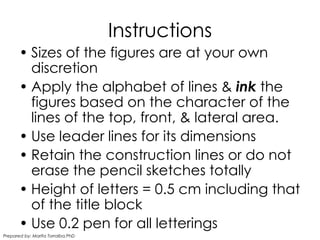
3. Instructions
Sizes of the figures are at your own
discretion
Apply the alphabet of lines & ink the
figures based on the character of the
lines of the top, front, & lateral area.
Use leader lines for its dimensions
Retain the construction lines or do not
erase the pencil sketches totally
Height of letters = 0.5 cm including that
of the title block
Use 0.2 pen for all letterings
Prepared by: Marifa Torralba,PhD
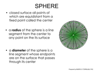
4. SPHERE
closed surface all points of
which are equidistant from a
fixed point called the center
a radius of the sphere is a line
segment from the center to
any point on the its surface
a diameter of the sphere is a
line segment whose endpoints
are on the surface that passes
through its center
Prepared by MARIFA S TORRALBA, PhD
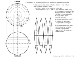
5. TOP VIEW
Construction by the Polycylindric/Gore method- quarter development
1. Draw concentric circles in the top (letters) lines in front
are diameters of these circles
2. divide a quadrant to equal central angles
3. measure arcs 1-2, 2-3, 3-4, 4-5 and draw line at the midpt
4. measure circumferential arc
from great circle (E )to the nxt
P 5 circle in the front view ( D )
5. measure the chord
P of circle D in top
A
6. Repeat steps 4 and 5 until P
4
B A 7. Trace a curve at each
endpoints to form a gore
C 3
D B
8. Using the developed gore
E 2
1 as template, lay out other
C gores to complete the
D
approximate development
P of the sphere
A
B
1 2 3 4 5
C
D
E
FRONT VIEW Prepared by: MARIFA S. TORRALBA, PhD
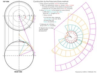
6. TOP VIEW Construction by the Polyconic/Zone method
1. Draw circle A and draw chord in the front view
2. With P as vertex/pivot, draw arc whose radius = chord
3. Divide one quarter of the sphere to equal sectors
4. Measure arc in A (top) & lay it off in arc (16 parts)
5. Draw line tangent to the sphere at circle A (front)
6. With that line tangent as radius,
draw the arc tangent to arc
P A B C 5 7. Draw circle B
8. In the front view, measure
line tangent + arc bet. A& B.
This becomes the
Radius of another arc
4
9. Measure arc in B (top)
& lay it off in arc (16 parts)
3 10. Repeat step 5 to finsih
half the sphere
2 development
1
P
P
A
B
C
E
FRONT VIEW Prepared by: MARIFA S. TORRALBA, PhD