srm
- 1. Smooth transition between optimal control modes in SWITCH RELUCTANCE MOTOR By- Badal Patnaik - 1001227260 Sanjit Debta - 1001227317 D. Gouri Sankar - 1001227269 Debendra Kido - 1001227267 Ananya Subhadarsinee - 1001227255
- 2. Content âĒ Introduction âĒ Principle of operation âĒ Characteristics âĒ General control strategy âĒ Modes of operation âĒ Simulink model for proposed controller âĒ Simulation results and Analysis âĒ Conclusion âĒ References
- 3. Introduction âĒ Concept of SRM-1938 âĒ Practical realization-mid 1960s,after the evolution of power electronics & computer aided EM design âĒ Also known as : -Variable Reluctance Motor -Brushless Reluctance Motor -Commutated Reluctance Motor
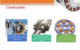
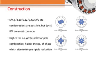
- 4. Construction Itâs a doubly-salient, singly- excited, independent stator exited motor The stator is same as PM motor but the rotor is simpler having no permanent magnet Stator windings on diametrically opposite poles are connected in series or parallel to form one phase
- 5. Construction âĒ 6/4,8/4,10/6,12/6,4/2,2/2 etc configurations are possible, but 6/4 & 8/4 are most common âĒ Higher the no. of stator/rotor pole combination, higher the no. of phase which aide to torque ripple reduction
- 6. Content âĒ Introduction âĒ Principle of operation âĒ Characteristics âĒ General control strategy âĒ Modes of operation âĒ Simulink model for proposed controller âĒ Simulation results and Analysis âĒ Conclusion âĒ References
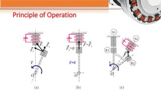
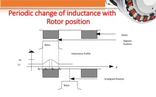
- 8. Principle of Operation âĒ Inductance of stator phase winding varies with rotor position âĒ Torque is produced only during variation of inductance âĒ Current is made available only during this variation, hence the need for rotor position feed back sensor
- 9. Periodic change of inductance with Rotor position Rotor Unaligned Position Lu La Inductance Profile Stator Aligned PositionRotor Îļ1 Îļ3Îļ2 Îļ4 Îļ L
- 10. Content âĒ Introduction âĒ Principle of operation âĒ Characteristics âĒ General control strategy âĒ Modes of operation âĒ Simulink model for proposed controller âĒ Simulation results and Analysis âĒ Conclusion âĒ References
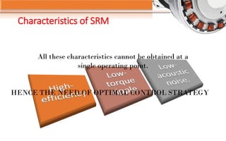
- 11. Characteristics of SRM All these characteristics cannot be obtained at a single operating point. HENCE THE NEED OF OPTIMAL CONTROL STRATEGY
- 12. Content âĒ Introduction âĒ Principle of operation âĒ Characteristics âĒ General control strategy âĒ Modes of operation âĒ Simulink model for proposed controller âĒ Simulation results and Analysis âĒ Conclusion âĒ References
- 13. General Control Strategies Voltage Source control Hysteresis current control
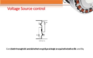
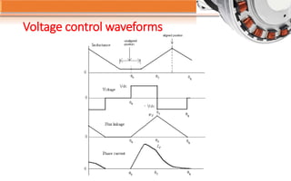
- 14. Voltage Source control Both transistors are switched on at Îļ0and both are switched off at ÎļcConducts through D2 and D1 when negative voltage is applied between Îļc and Îļq
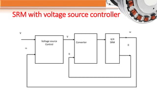
- 16. V Voltage source Control Converter 6/4 SRM ïą V ïą ï· Ï SRM with voltage source controller
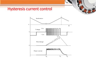
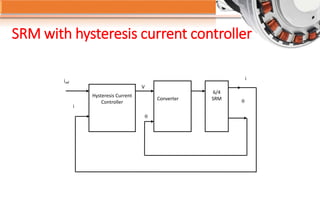
- 17. Hysteresis current control âĒ Power switches are switched off or on according to the current is greater than or less than a reference current. âĒ The instantaneous phase current is measured and fed back to summing junction. âĒ The error is used directly to control the states of power transistors.
- 19. SRM with hysteresis current controller iref Hysteresis Current Controller Converter 6/4 SRM ïą V ïą i i
- 20. Content âĒ Introduction âĒ Principle of operation âĒ Characteristics âĒ General control strategy âĒ Modes of operation âĒ Simulink model for proposed controller âĒ Simulation results and Analysis âĒ Conclusion âĒ References
- 21. Modes of operation Single pulse mode PWM mode
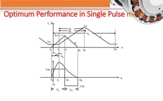
- 22. Optimum Performance in Single Pulse mode L, ÎĻ La L Lu ÎĻc ÎĻ Îļ ÎļuÎļaÎļqÎļcÎļ1 Îļu Îļ0 Îļ01 Îļ Îēs Îēr Îąp ÎļqÎļcÎļ1 Îļu Îļ0 Îļe1 Îļe2 -Vdc Vdc
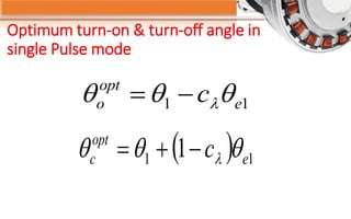
- 23. Optimum turn-on & turn-off angle in single Pulse mode 11 e opt o c ïąïąïą ïŽïï― ïĻ ïĐ 11 1 e opt c c ïąïąïą ïŽïïŦï―
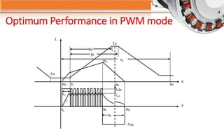
- 24. Optimum Performance in PWM mode La Lu L Îļ Îļ Îļ1Îļu Îļ01 i Îļ0 Îļc Îļq Îļe Îļa Vdc iref ÎĻc -Vdc Îļu Îēs Îēr Îąp
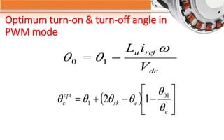
- 25. Optimum turn-on & turn-off angle in PWM mode dc refu V iL ï· ïąïą ïï― 10 ïĻ ïĐ ïš ïŧ ïđ ïŠ ïŦ ïĐ ïïïŦï― e esk opt c ïą ïą ïąïąïąïą 01 1 12
- 26. Content âĒ Introduction âĒ Principle of operation âĒ Characteristics âĒ General control strategy âĒ Modes of operation âĒ Simulink model for proposed controller âĒ Simulation results and Analysis âĒ Conclusion âĒ References
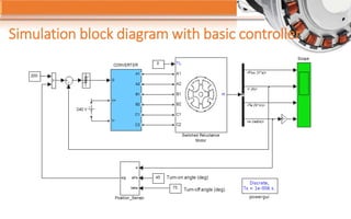
- 27. Simulation block diagram with basic controller
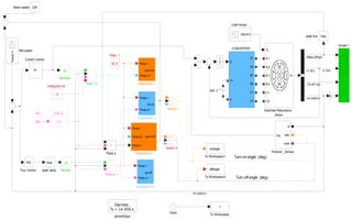
- 28. Simulation block diagram with developed controller Turn-off angle (deg) Turn-on angle (deg) powergui Discrete , Ts = 1e-006 s. peak value max peak flux max Vdc 240 Unaligned ind -C- To Workspace2 offangle To Workspace1 onangle To Workspace t Theta e 1 Theta e Theta 1 52.5 Theta 01 Switched Reluctance Motor TL m A1 A2 B1 B2 C1 C2 A1 A2 B1 B2 C1 C2 TL m Switch 2 Switch1 Subsystem-4 Theta 1 Theta e1 sp-off Subsystem-3 Theta 1 Theta e1 sp-on Subsystem-2 Theta 1 Theta 01 Theta e pwm-off Subsystem-1 Theta 1 Theta 01 pwm-on Scope 1 Ref speed Signal4 Ref flux |u| Position _Sensor w alfa beta sig Load torque Signal 2 -K- Flux Control PID Eqn -3 1/u Current control PI Clock CONVERTER G V+ V- A1 A2 B1 B2 C1 C2 Base speed 325 Abstract |u| 240 V <Flux (V*s)><Flux (V*s)><Flux (V*s)><Flux (V*s)><Flux (V*s)><Flux (V*s)> <w (rad/s)> <w (rad/s)> <I (A)><I (A)> <Te (N*m)>
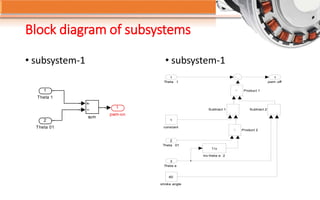
- 29. Block diagram of subsystems âĒ subsystem-1 âĒ subsystem-1 1 pwm-on sum 2 Theta 01 1 Theta 1 pwm -off 1 stroke angle 60 constant 1 Subtract 2Subtract 1 Product 2 Product 1 Inv theta e 2 1/u Theta e 3 Theta 01 2 Theta 1 1
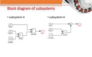
- 30. Block diagram of subsystems âĒ subsystem-3 âĒ subsystem-4 1 sp-on 0.25 c-lambda Pre-eqn Eqn-sp-on 2 Theta e1 1 Theta 1 1 sp-off Product0.75 1-c lambda 2 Theta e1 1 Theta 1
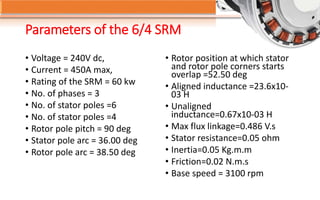
- 31. Parameters of the 6/4 SRM âĒ Voltage = 240V dc, âĒ Current = 450A max, âĒ Rating of the SRM = 60 kw âĒ No. of phases = 3 âĒ No. of stator poles =6 âĒ No. of stator poles =4 âĒ Rotor pole pitch = 90 deg âĒ Stator pole arc = 36.00 deg âĒ Rotor pole arc = 38.50 deg âĒ Rotor position at which stator and rotor pole corners starts overlap =52.50 deg âĒ Aligned inductance =23.6x10- 03 H âĒ Unaligned inductance=0.67x10-03 H âĒ Max flux linkage=0.486 V.s âĒ Stator resistance=0.05 ohm âĒ Inertia=0.05 Kg.m.m âĒ Friction=0.02 N.m.s âĒ Base speed = 3100 rpm
- 32. Content âĒ Introduction âĒ Principle of operation âĒ Characteristics âĒ General control strategy âĒ Modes of operation âĒ Simulink model for proposed controller âĒ Simulation results and Analysis âĒ Conclusion âĒ References
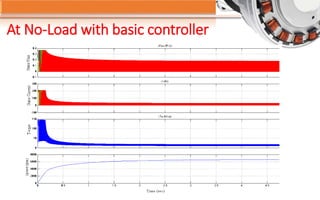
- 34. At No-Load with basic controller
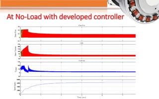
- 35. At No-Load with developed controller
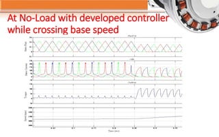
- 36. At No-Load with developed controller while crossing base speed
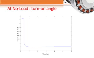
- 37. At No-Load : turn-on angle Tu rn on an gle (d eg ) Time (sec)
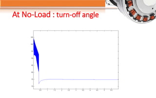
- 38. At No-Load : turn-off angle
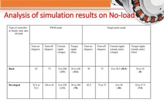
- 39. Analysis of simulation results on No-load Type of controller at steady state rpm 0f 6560 PWM mode Single pulse mode Turn-on (degree) Turn-off (degree) Current ripple (Amps) Torque ripple (Nm) Turn-on (degree) Turn-off (degree) Current ripple (steady state) (Amps) Torque ripple (steady state) (Nm) Basic 45 75 0 to 200 (200) 36 to 148 (112) 45 75 0 to 30.5 (30.5) 10 to 18 (8) Developed 52.5 to 52.3 104 to 81 0 to 230 (230) 30 to 100 (70) 45.2 72 to 75 0 to 30 (30) 10 to 17.5 (7.5)
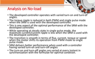
- 40. Analysis on No-load âĒ The developed controller operates with varied turn-on and turn-of angles. âĒ The torque ripple is reduced in both PWM and single pulse mode when the SRM is used with the developed controller. âĒ This is one aspect of the optimal performance of the SRM with the developed controller. âĒ While operating at steady state in single pulse mode, the maximum current/current ripple is less when the SRM is used with the developed controller. âĒ The transition is smooth in terms of flux, current, torque or speed when the motor shifts its operation from PWM mode to single pulse mode. âĒ SRM delivers better performance when used with a controller having varied turn-on and turn-off angles âĒ The turn-on and turn-off angles are varied at every instant in synchronization with the formulae for optimal condition.
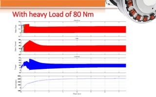
- 41. With heavy Load of 80 Nm
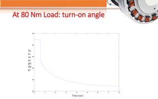
- 42. At 80 Nm Load: turn-on angle Tu rn on an gle (de g) Time (sec) 0 1 2 3 4 5 6 7 8 30 35 40 45 50 55
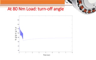
- 43. At 80 Nm Load: turn-off angle Tu rn off an gle (de g) Time (sec) 0 1 2 3 4 5 6 7 8 20 40 60 80 100 120 140 160
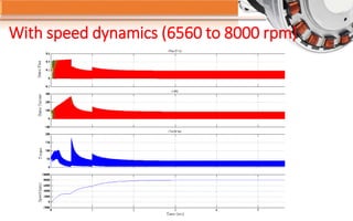
- 44. With speed dynamics (6560 to 8000 rpm)
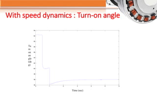
- 45. With speed dynamics : Turn-on angle Tu rn on an gle (de g) Time (sec) 0 1 2 3 4 5 6 34 36 38 40 42 44 46 48 50 52 54
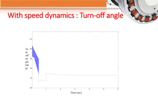
- 46. Tu rn off an gle (de g) Time (sec) 1 2 3 4 5 6 60 70 80 90 100 110 With speed dynamics : Turn-off angle
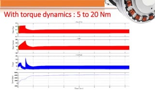
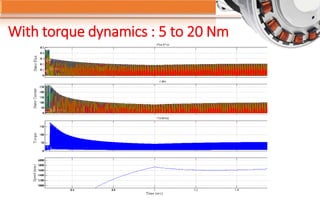
- 47. With torque dynamics : 5 to 20 Nm
- 48. With torque dynamics : 5 to 20 Nm
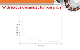
- 49. Tu rn on an gle (de g) Time (sec) 0 1 2 3 4 5 6 7 8 34 36 38 40 42 44 46 48 50 52 54 With torque dynamics : turn-on angle
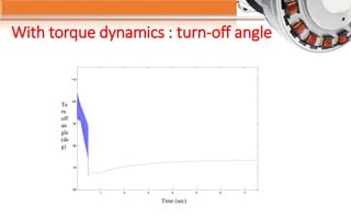
- 50. With torque dynamics : turn-off angle Tu rn off an gle (de g) Time (sec) 1 2 3 4 5 6 7 60 70 80 90 100 110
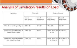
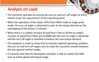
- 51. Analysis of Simulation results on Load Application PWM mode Single-pulse mode Turn-on angle (degree) Turn-off angle(degree) Turn-on angle (degree) Turn-off angle(degree) 80 Nm of load at 6560 rpm ref speed 52.5 to 52 128 to 72 43 to 32.2 64 to 78 Steep increase of load from 5 to 20 Nm at 6560 rpm ref speed 52.5 to 52.2 104 to74 41.2 to 40 to 40.2 to 35.8 66 to 68 to73 Steep increase of speed from 6560 to 8000 rpm at 5 Nm of load 52.5 to 52.2 104 to74 41.2 to 40 to 40.2 to 34.4 to 36 67 to 68 to 75 to 73
- 52. Analysis on Load âĒ The controller operates by varying the turn-on and turn-off angles at every instant as per the requirement of that operating point. âĒ When the operation of the motor shifts from PWM mode to single pulse mode, the turn-on angle is advanced to cater to the torque demand as the overlapping of the phases is reduced. âĒ When there is a sudden increase of load from 5 Nm to 20 Nm or sudden increase of speed from 5650 rpm to 8000 rpm the turn-on angle is advanced and the turn-off angle is retarded to balance the new torque demand. âĒ The emphasis is made to show that to maintain optimal operating condition the turn-on and turn-off angles vary to make the transition smooth between the two optimal control modes âĒ It is proved now that the developed controller is able to control the SRM over its entire speed and torque range.
- 53. Content âĒ Introduction âĒ Principle of operation âĒ Characteristics âĒ General control strategy âĒ Modes of operation âĒ Simulink model for proposed controller âĒ Simulation results and Analysis âĒ Conclusion âĒ References
- 54. CONCLUSION âĒ This project studies optimal control modes of the SRM by striking a balance between maximum efficiency and minimum torque ripple and thus calculates the optimum switch on angles and switch off angles. âĒ The turn on and turn off angles are calculated through simple formulas and implemented through Simulink building blocks. âĒ The optimum controller determines the turn-on and turn-off angles at every instant and accordingly the converter switches are fired to cater to the torque and speed demand of that instant. âĒ To validate the effectiveness of the controller, simulation is carried out on a variety of load and speed combination and the effectiveness is verified.
- 55. REFERENCES [1] C.J. Van Duijn, âDevelopment of methods, algorithms and soft wares for optimal design of switched reluctance drivesâ [2] F. Soares and P.J. Costa Branco, âSimulation of a 6/4 switched reluctance motor based on Matlab/Simulink environment [3] R Krishnan,â Switched Reluctance Motor Drives; Modeling, Simulation, Analysis, Design and Applicationsâ [4] Han-Kyung Bae, âControl of Switched Reluctance Motors considering mutual inductanceâ [5] Ardeshir Motomedi-Sedeh, âSpeed control of switched reluctance motorsâ [6] M. T. DiRenzo, "Switched Reluctance Motor Control â Basic Operation and Example Using the TMS320F240, Texas Instruments Application Note," 2000. [7] C. Mademlis and I. Kioskeridis, âPerformance optimization in switched reluctance motor drives with online commutation angle control,â IEEE [8] C. Mademlis and I. Kioskeridis, âMaximum efficiency in Single Pulse Controlled switched reluctance motor drives,â IEEE [9] C. Mademlis and I. Kioskeridis, âSmooth Transition between Optimal Control Modes in switched reluctance motoring,â IEEE [10] Matlab R 2008a, Version 7.6
- 56. 1
- 57. 1
- 58. 1

![REFERENCES
[1] C.J. Van Duijn, âDevelopment of methods, algorithms and soft wares for optimal design of
switched reluctance drivesâ
[2] F. Soares and P.J. Costa Branco, âSimulation of a 6/4 switched reluctance motor based on
Matlab/Simulink environment
[3] R Krishnan,â Switched Reluctance Motor Drives; Modeling, Simulation, Analysis, Design and
Applicationsâ
[4] Han-Kyung Bae, âControl of Switched Reluctance Motors considering mutual inductanceâ
[5] Ardeshir Motomedi-Sedeh, âSpeed control of switched reluctance motorsâ
[6] M. T. DiRenzo, "Switched Reluctance Motor Control â Basic Operation and Example Using the
TMS320F240, Texas Instruments Application Note," 2000.
[7] C. Mademlis and I. Kioskeridis, âPerformance optimization in switched reluctance motor drives
with online commutation angle control,â IEEE
[8] C. Mademlis and I. Kioskeridis, âMaximum efficiency in Single Pulse Controlled switched
reluctance motor drives,â IEEE
[9] C. Mademlis and I. Kioskeridis, âSmooth Transition between Optimal Control Modes in switched
reluctance motoring,â IEEE
[10] Matlab R 2008a, Version 7.6](https://image.slidesharecdn.com/e1577319-71e9-4466-a65b-0e66caeb06f0-150722104258-lva1-app6892/85/srm-55-320.jpg)


