ºÝºÝߣ

ºÝºÝߣShare a Scribd company logo
Sequence of Operation Typical for (6) Boiler Rooms

Boiler Safeties

All Boiler flame safeguard controls, low water / make-up feed controls and burner shutdown
controls are integral to the original boiler installation. These circuits are factory installed and
have not been interrupted by the EMS control system.

EZAutomation Control Panel

The EZAutomation Control Panel consists of the following:

    1.    32-point capable PLC
    2.   (2) Two Analog Input Modules (16-point capable)
    3.   (1) One DC Voltage Digital Output Module (8-point capable)
    4.   (1) One DC Voltage Digital Input Module (8-point capable)
    5.   3-pole 10-amp circuit breaker
    6.   24vdc power supply
    7.   5vdc power supply
    8.   24vac power supply
    9.   Boiler Enable Relay

EZAutomation Control Field Devices

The EZAutomation Control Field Devices consist of the following:

    1.   Steam Pressure Transmitter
    2.   Outside Air Temperature Sensor
    3.   Boiler Burner Proof Relay
    4.   Boiler Burner Flame Fail Relay
    5.   Combustion Damper & Motor Actuator
    6.   Combustion Damper Boiler Start Relay

Summer Control

PLC Program Sequence

From 12:00 Midnight on April 30th through 12:00 Midnight October 1st, all control devices will
be indexed to their standby positions and the steam boiler will shut down.

    1.   Steam Boiler Combustion Damper – Closed
    2.   Boiler Enable Relay – Normally Open
    3.   Domestic Hot Water Combustion Louver will always be open
    4.   The Domestic Hot Water Boiler and Indirect Hot Water Tank will cycle continuously
Winter Control

PLC Program Sequence

From 12:00 Midnight on October 1st through 12:00 Midnight April 30th, the steam boiler system
will be enabled. The outside air temperature sensor will initialize a calculation comparing the
outside air temperature with a fixed indoor temperature set point of 70 deg F. As the outside air
temperature decreases, the algorithm calculates the heat loss of the building structure and creates
two time schedules, one for burner run time and one for burner off time. The algorithm will
calculate how long the burner should run to produce and maintain 3 PSIG steam pressure to
input enough heat into the building to maintain the 70 deg F set point at any given outside air
temperature. The second timer will calculate how long to disable the burner and allow the heat
absorbed by the piping, radiators and structure to continue to heat the living space. These
calculations are dynamic and are re-calculated every second. Simply, as the OAT decreases, the
burner on time increases and the burner off time decreases. As the OAT increases, the burner on
time decreases and the burner off time increases.

These calculations depend on the boiler system and building structure to function as designed.
This requires that all condensate is returned to the condensate system tanks and pumped back to
the boiler and all sources of outside air infiltration are reduced as much as possible.

Relay Logic & Device Actuation

Upon a call for burner RUN, the boiler enable relay (R-1) is energized and CLOSES the
normally open contact. This passes control power to the combustion damper actuator (D-1).
When the damper drives open over 70%, the damper end switch CLOSES and energizes the
burner start relay (R-2). The (R-2) normally open contact CLOSES and completes the boiler
control circuit which begins the burner firing sequence. When the burner ON Timer expires, the
boiler enable relay (R-1) is de-energized, closing the Combustion Damper and initiating a burner
shut down. The burner OFF timer will now disable the boiler until the OFF timer expires. This
sequence will repeat until the OAT rises above 60 deg F or the Summer Control program is
indexed on.

The Domestic Hot Water Boiler and Indirect Hot Water Tank will cycle continuously.

More Related Content

What's hot (20)

Generator cooling and sealing system 2
Generator cooling and sealing system 2Generator cooling and sealing system 2
Generator cooling and sealing system 2
Mohammad Basid
Ìý
Boiler Purging-Logic, Importance & Working
Boiler Purging-Logic, Importance & WorkingBoiler Purging-Logic, Importance & Working
Boiler Purging-Logic, Importance & Working
Tahoor Alam Khan
Ìý
Power Plant Boiler feed pump
Power Plant Boiler feed pump Power Plant Boiler feed pump
Power Plant Boiler feed pump
Vundavilli Gautham
Ìý
boiler turbine emergency
boiler turbine emergencyboiler turbine emergency
boiler turbine emergency
mitravanu mishra
Ìý
36809944-Gas-Turbine-Control.ppt
36809944-Gas-Turbine-Control.ppt36809944-Gas-Turbine-Control.ppt
36809944-Gas-Turbine-Control.ppt
SreekanthMylavarapu1
Ìý
Thermal Power Plant Simulator, Cold, warm and Hot rolling of Steam Turbine
Thermal Power Plant Simulator, Cold, warm and Hot rolling of Steam TurbineThermal Power Plant Simulator, Cold, warm and Hot rolling of Steam Turbine
Thermal Power Plant Simulator, Cold, warm and Hot rolling of Steam Turbine
Manohar Tatwawadi
Ìý
Steam blowing procedure
Steam blowing procedure Steam blowing procedure
Steam blowing procedure
Vaibhav Paydelwar
Ìý
Final Turbine rolling ppt Akshay.pptx
Final Turbine rolling ppt Akshay.pptxFinal Turbine rolling ppt Akshay.pptx
Final Turbine rolling ppt Akshay.pptx
BhimarajuKanireddy
Ìý
Hp/ lp bypass system for steam turbines
Hp/ lp bypass system for steam turbinesHp/ lp bypass system for steam turbines
Hp/ lp bypass system for steam turbines
Boben Anto Chemmannoor
Ìý
Training material for air preheater
Training material for air preheaterTraining material for air preheater
Training material for air preheater
HOANG VAN DUC
Ìý
Cfbc burner startup sequence
Cfbc burner startup sequenceCfbc burner startup sequence
Cfbc burner startup sequence
Ashvani Shukla
Ìý
AUTOMATIC TURBINE RUNUP SYSTEM
AUTOMATIC TURBINE RUNUP SYSTEMAUTOMATIC TURBINE RUNUP SYSTEM
AUTOMATIC TURBINE RUNUP SYSTEM
kumarswamy927
Ìý
Steam Blow out
Steam Blow outSteam Blow out
Steam Blow out
EGYPT ENGINEERING SERVICES "EGYPTROL"
Ìý
Boiler -Emergency Handling
 Boiler -Emergency Handling Boiler -Emergency Handling
Boiler -Emergency Handling
Ashish Kumar Jain
Ìý
Unit lightup synchronisation & shutdown
Unit lightup synchronisation & shutdownUnit lightup synchronisation & shutdown
Unit lightup synchronisation & shutdown
Nitin Mahalle
Ìý
Steam Turbine Performance in TPS
Steam Turbine Performance in TPSSteam Turbine Performance in TPS
Steam Turbine Performance in TPS
Manohar Tatwawadi
Ìý
Boiler Water Circulation Pumps
Boiler Water Circulation PumpsBoiler Water Circulation Pumps
Boiler Water Circulation Pumps
Gerard B. Hawkins
Ìý
Handling of turbine side emergencies
Handling of turbine side emergenciesHandling of turbine side emergencies
Handling of turbine side emergencies
Manohar Tatwawadi
Ìý
Boiler feed pump recirculation valve problem
Boiler feed pump recirculation valve problemBoiler feed pump recirculation valve problem
Boiler feed pump recirculation valve problem
Vudugundla Kodandapani
Ìý
Design Considerations for Antisurge Valve Sizing
Design Considerations for Antisurge Valve SizingDesign Considerations for Antisurge Valve Sizing
Design Considerations for Antisurge Valve Sizing
Vijay Sarathy
Ìý
Generator cooling and sealing system 2
Generator cooling and sealing system 2Generator cooling and sealing system 2
Generator cooling and sealing system 2
Mohammad Basid
Ìý
Boiler Purging-Logic, Importance & Working
Boiler Purging-Logic, Importance & WorkingBoiler Purging-Logic, Importance & Working
Boiler Purging-Logic, Importance & Working
Tahoor Alam Khan
Ìý
Power Plant Boiler feed pump
Power Plant Boiler feed pump Power Plant Boiler feed pump
Power Plant Boiler feed pump
Vundavilli Gautham
Ìý
boiler turbine emergency
boiler turbine emergencyboiler turbine emergency
boiler turbine emergency
mitravanu mishra
Ìý
36809944-Gas-Turbine-Control.ppt
36809944-Gas-Turbine-Control.ppt36809944-Gas-Turbine-Control.ppt
36809944-Gas-Turbine-Control.ppt
SreekanthMylavarapu1
Ìý
Thermal Power Plant Simulator, Cold, warm and Hot rolling of Steam Turbine
Thermal Power Plant Simulator, Cold, warm and Hot rolling of Steam TurbineThermal Power Plant Simulator, Cold, warm and Hot rolling of Steam Turbine
Thermal Power Plant Simulator, Cold, warm and Hot rolling of Steam Turbine
Manohar Tatwawadi
Ìý
Steam blowing procedure
Steam blowing procedure Steam blowing procedure
Steam blowing procedure
Vaibhav Paydelwar
Ìý
Final Turbine rolling ppt Akshay.pptx
Final Turbine rolling ppt Akshay.pptxFinal Turbine rolling ppt Akshay.pptx
Final Turbine rolling ppt Akshay.pptx
BhimarajuKanireddy
Ìý
Hp/ lp bypass system for steam turbines
Hp/ lp bypass system for steam turbinesHp/ lp bypass system for steam turbines
Hp/ lp bypass system for steam turbines
Boben Anto Chemmannoor
Ìý
Training material for air preheater
Training material for air preheaterTraining material for air preheater
Training material for air preheater
HOANG VAN DUC
Ìý
Cfbc burner startup sequence
Cfbc burner startup sequenceCfbc burner startup sequence
Cfbc burner startup sequence
Ashvani Shukla
Ìý
AUTOMATIC TURBINE RUNUP SYSTEM
AUTOMATIC TURBINE RUNUP SYSTEMAUTOMATIC TURBINE RUNUP SYSTEM
AUTOMATIC TURBINE RUNUP SYSTEM
kumarswamy927
Ìý
Boiler -Emergency Handling
 Boiler -Emergency Handling Boiler -Emergency Handling
Boiler -Emergency Handling
Ashish Kumar Jain
Ìý
Unit lightup synchronisation & shutdown
Unit lightup synchronisation & shutdownUnit lightup synchronisation & shutdown
Unit lightup synchronisation & shutdown
Nitin Mahalle
Ìý
Steam Turbine Performance in TPS
Steam Turbine Performance in TPSSteam Turbine Performance in TPS
Steam Turbine Performance in TPS
Manohar Tatwawadi
Ìý
Boiler Water Circulation Pumps
Boiler Water Circulation PumpsBoiler Water Circulation Pumps
Boiler Water Circulation Pumps
Gerard B. Hawkins
Ìý
Handling of turbine side emergencies
Handling of turbine side emergenciesHandling of turbine side emergencies
Handling of turbine side emergencies
Manohar Tatwawadi
Ìý
Boiler feed pump recirculation valve problem
Boiler feed pump recirculation valve problemBoiler feed pump recirculation valve problem
Boiler feed pump recirculation valve problem
Vudugundla Kodandapani
Ìý
Design Considerations for Antisurge Valve Sizing
Design Considerations for Antisurge Valve SizingDesign Considerations for Antisurge Valve Sizing
Design Considerations for Antisurge Valve Sizing
Vijay Sarathy
Ìý

Viewers also liked (9)

John Castoro 091212
John Castoro 091212John Castoro 091212
John Castoro 091212
HVAC Building Management Systems, LLC
Ìý
Asp Riv Boiler Damper Control
Asp Riv Boiler Damper ControlAsp Riv Boiler Damper Control
Asp Riv Boiler Damper Control
HVAC Building Management Systems, LLC
Ìý
Chap 43
Chap 43Chap 43
Chap 43
Anai Gaia
Ìý
One Solution for Simulation of Steam Turbine Power Upon 210MW
One Solution for Simulation of Steam Turbine Power Upon 210MW One Solution for Simulation of Steam Turbine Power Upon 210MW
One Solution for Simulation of Steam Turbine Power Upon 210MW
pupin_proces_automation
Ìý
Unit 4 bme i.c engine
Unit 4  bme i.c engineUnit 4  bme i.c engine
Unit 4 bme i.c engine
Rai University
Ìý
Kannan
Kannan Kannan
Kannan
kannan perumal
Ìý
Boiler book 2005
Boiler book 2005Boiler book 2005
Boiler book 2005
RUBÉN ROMERO SOTO
Ìý
Boiler mounting
Boiler mountingBoiler mounting
Boiler mounting
bhavesh patwa
Ìý
Boiler Introduction
Boiler IntroductionBoiler Introduction
Boiler Introduction
controlsystemworld
Ìý

Similar to Steam Boiler Sequence Of Operation (20)

PresentationGGSSTP_Atul
PresentationGGSSTP_AtulPresentationGGSSTP_Atul
PresentationGGSSTP_Atul
Atul Kataria
Ìý
94716008 burner-management-system-et-2008
94716008 burner-management-system-et-200894716008 burner-management-system-et-2008
94716008 burner-management-system-et-2008
Mowaten Masry
Ìý
All You Need To Know About Furnace Control Boards
All You Need To Know About Furnace Control BoardsAll You Need To Know About Furnace Control Boards
All You Need To Know About Furnace Control Boards
ACEHVACPARTS
Ìý
Boiler ppt
Boiler pptBoiler ppt
Boiler ppt
Er Ramgarhia
Ìý
INTERNSHIP (1).pptx
INTERNSHIP (1).pptxINTERNSHIP (1).pptx
INTERNSHIP (1).pptx
Googles3
Ìý
Surefire pr1 Installation-User Guide (1)
Surefire pr1 Installation-User Guide (1)Surefire pr1 Installation-User Guide (1)
Surefire pr1 Installation-User Guide (1)
Damian Mitchell
Ìý
Chapter 55 Computer Sensors
Chapter 55 Computer SensorsChapter 55 Computer Sensors
Chapter 55 Computer Sensors
mcfalltj
Ìý
419687556-Boiler-Interlock-Protection-System.pptx
419687556-Boiler-Interlock-Protection-System.pptx419687556-Boiler-Interlock-Protection-System.pptx
419687556-Boiler-Interlock-Protection-System.pptx
BHAGVATAWARGAND
Ìý
HIU Design Guide
HIU Design GuideHIU Design Guide
HIU Design Guide
Paul Longman
Ìý
motorised valves
motorised valvesmotorised valves
motorised valves
catherinelindsay
Ìý
Elec lab project
Elec lab projectElec lab project
Elec lab project
Pratik Agarwal
Ìý
On Power Plant Operation cource In Urdu by Khalid ayaz Soomro.pdf
On Power Plant Operation  cource In Urdu by Khalid ayaz Soomro.pdfOn Power Plant Operation  cource In Urdu by Khalid ayaz Soomro.pdf
On Power Plant Operation cource In Urdu by Khalid ayaz Soomro.pdf
KhalidAyaz3
Ìý
Hydraulic flushing rig ppt
Hydraulic flushing rig pptHydraulic flushing rig ppt
Hydraulic flushing rig ppt
Neometrix_Engineering_Pvt_Ltd
Ìý
Development of Solar Energy and Gas Coupled Heat Supply System
Development of Solar Energy and Gas Coupled Heat Supply SystemDevelopment of Solar Energy and Gas Coupled Heat Supply System
Development of Solar Energy and Gas Coupled Heat Supply System
IJRESJOURNAL
Ìý
SIPAT 660 MW Turbo- Governing & Protection System.ppt
SIPAT 660 MW Turbo- Governing & Protection System.pptSIPAT 660 MW Turbo- Governing & Protection System.ppt
SIPAT 660 MW Turbo- Governing & Protection System.ppt
MarcWorld
Ìý
Chapter8
Chapter8Chapter8
Chapter8
Abdul Majeed
Ìý
Gas Turbine Power Plant.pdf
Gas Turbine Power Plant.pdfGas Turbine Power Plant.pdf
Gas Turbine Power Plant.pdf
Dronacharya Group of Institutions, Greater Noida
Ìý
BMS FSSS.pptx
BMS FSSS.pptxBMS FSSS.pptx
BMS FSSS.pptx
ManzoorAlam40
Ìý
Burner Management System ( FSSS).pptx
Burner Management System ( FSSS).pptxBurner Management System ( FSSS).pptx
Burner Management System ( FSSS).pptx
ManzoorAlam40
Ìý
Sample Question and answer for power plants
Sample Question and answer for power plantsSample Question and answer for power plants
Sample Question and answer for power plants
Vikeshgond2
Ìý
PresentationGGSSTP_Atul
PresentationGGSSTP_AtulPresentationGGSSTP_Atul
PresentationGGSSTP_Atul
Atul Kataria
Ìý
94716008 burner-management-system-et-2008
94716008 burner-management-system-et-200894716008 burner-management-system-et-2008
94716008 burner-management-system-et-2008
Mowaten Masry
Ìý
All You Need To Know About Furnace Control Boards
All You Need To Know About Furnace Control BoardsAll You Need To Know About Furnace Control Boards
All You Need To Know About Furnace Control Boards
ACEHVACPARTS
Ìý
INTERNSHIP (1).pptx
INTERNSHIP (1).pptxINTERNSHIP (1).pptx
INTERNSHIP (1).pptx
Googles3
Ìý
Surefire pr1 Installation-User Guide (1)
Surefire pr1 Installation-User Guide (1)Surefire pr1 Installation-User Guide (1)
Surefire pr1 Installation-User Guide (1)
Damian Mitchell
Ìý
Chapter 55 Computer Sensors
Chapter 55 Computer SensorsChapter 55 Computer Sensors
Chapter 55 Computer Sensors
mcfalltj
Ìý
419687556-Boiler-Interlock-Protection-System.pptx
419687556-Boiler-Interlock-Protection-System.pptx419687556-Boiler-Interlock-Protection-System.pptx
419687556-Boiler-Interlock-Protection-System.pptx
BHAGVATAWARGAND
Ìý
HIU Design Guide
HIU Design GuideHIU Design Guide
HIU Design Guide
Paul Longman
Ìý
Elec lab project
Elec lab projectElec lab project
Elec lab project
Pratik Agarwal
Ìý
On Power Plant Operation cource In Urdu by Khalid ayaz Soomro.pdf
On Power Plant Operation  cource In Urdu by Khalid ayaz Soomro.pdfOn Power Plant Operation  cource In Urdu by Khalid ayaz Soomro.pdf
On Power Plant Operation cource In Urdu by Khalid ayaz Soomro.pdf
KhalidAyaz3
Ìý
Development of Solar Energy and Gas Coupled Heat Supply System
Development of Solar Energy and Gas Coupled Heat Supply SystemDevelopment of Solar Energy and Gas Coupled Heat Supply System
Development of Solar Energy and Gas Coupled Heat Supply System
IJRESJOURNAL
Ìý
SIPAT 660 MW Turbo- Governing & Protection System.ppt
SIPAT 660 MW Turbo- Governing & Protection System.pptSIPAT 660 MW Turbo- Governing & Protection System.ppt
SIPAT 660 MW Turbo- Governing & Protection System.ppt
MarcWorld
Ìý
Burner Management System ( FSSS).pptx
Burner Management System ( FSSS).pptxBurner Management System ( FSSS).pptx
Burner Management System ( FSSS).pptx
ManzoorAlam40
Ìý
Sample Question and answer for power plants
Sample Question and answer for power plantsSample Question and answer for power plants
Sample Question and answer for power plants
Vikeshgond2
Ìý

Steam Boiler Sequence Of Operation

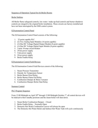
  • 1. Sequence of Operation Typical for (6) Boiler Rooms Boiler Safeties All Boiler flame safeguard controls, low water / make-up feed controls and burner shutdown controls are integral to the original boiler installation. These circuits are factory installed and have not been interrupted by the EMS control system. EZAutomation Control Panel The EZAutomation Control Panel consists of the following: 1. 32-point capable PLC 2. (2) Two Analog Input Modules (16-point capable) 3. (1) One DC Voltage Digital Output Module (8-point capable) 4. (1) One DC Voltage Digital Input Module (8-point capable) 5. 3-pole 10-amp circuit breaker 6. 24vdc power supply 7. 5vdc power supply 8. 24vac power supply 9. Boiler Enable Relay EZAutomation Control Field Devices The EZAutomation Control Field Devices consist of the following: 1. Steam Pressure Transmitter 2. Outside Air Temperature Sensor 3. Boiler Burner Proof Relay 4. Boiler Burner Flame Fail Relay 5. Combustion Damper & Motor Actuator 6. Combustion Damper Boiler Start Relay Summer Control PLC Program Sequence From 12:00 Midnight on April 30th through 12:00 Midnight October 1st, all control devices will be indexed to their standby positions and the steam boiler will shut down. 1. Steam Boiler Combustion Damper – Closed 2. Boiler Enable Relay – Normally Open 3. Domestic Hot Water Combustion Louver will always be open 4. The Domestic Hot Water Boiler and Indirect Hot Water Tank will cycle continuously
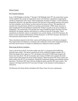
  • 2. Winter Control PLC Program Sequence From 12:00 Midnight on October 1st through 12:00 Midnight April 30th, the steam boiler system will be enabled. The outside air temperature sensor will initialize a calculation comparing the outside air temperature with a fixed indoor temperature set point of 70 deg F. As the outside air temperature decreases, the algorithm calculates the heat loss of the building structure and creates two time schedules, one for burner run time and one for burner off time. The algorithm will calculate how long the burner should run to produce and maintain 3 PSIG steam pressure to input enough heat into the building to maintain the 70 deg F set point at any given outside air temperature. The second timer will calculate how long to disable the burner and allow the heat absorbed by the piping, radiators and structure to continue to heat the living space. These calculations are dynamic and are re-calculated every second. Simply, as the OAT decreases, the burner on time increases and the burner off time decreases. As the OAT increases, the burner on time decreases and the burner off time increases. These calculations depend on the boiler system and building structure to function as designed. This requires that all condensate is returned to the condensate system tanks and pumped back to the boiler and all sources of outside air infiltration are reduced as much as possible. Relay Logic & Device Actuation Upon a call for burner RUN, the boiler enable relay (R-1) is energized and CLOSES the normally open contact. This passes control power to the combustion damper actuator (D-1). When the damper drives open over 70%, the damper end switch CLOSES and energizes the burner start relay (R-2). The (R-2) normally open contact CLOSES and completes the boiler control circuit which begins the burner firing sequence. When the burner ON Timer expires, the boiler enable relay (R-1) is de-energized, closing the Combustion Damper and initiating a burner shut down. The burner OFF timer will now disable the boiler until the OFF timer expires. This sequence will repeat until the OAT rises above 60 deg F or the Summer Control program is indexed on. The Domestic Hot Water Boiler and Indirect Hot Water Tank will cycle continuously.