Str
1 like840 views

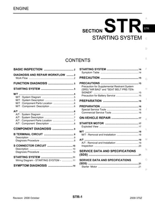
The document provides information on diagnosing and repairing starting systems. It describes manual and automatic transmission starting system diagrams, components, and descriptions. Diagnosis steps include inspecting the battery, starter motor, alternator, B terminal circuit, S connector circuit, and engine rotation. If issues are found, the document provides repair procedures for the starter motor. It also includes service data and specifications for the starter motor.
![DIAGNOSIS AND REPAIR WORKFLOW
< BASIC INSPECTION >
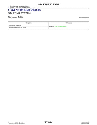
NOTE:
To ensure a complete and thorough diagnosis, the battery, starter motor and alternator test segments must be
done as a set from start to finish.
A
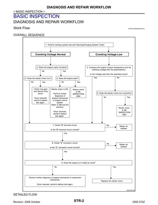
1.DIAGNOSIS WITH STARTING/CHARGING SYSTEM TESTER
Perform the starting system test with Starting/Charging System Tester (SST: J-44373). For details and operat- STR
ing instructions, refer to Technical Service Bulletin.
Test result
C
CRANKING VOLTAGE NORMAL>>GO TO 2.
CRANKING VOLTAGE LOW>>GO TO 5.
CHARGE BATTERY>>Perform the slow battery charging procedure. (Initial rate of charge is 10A for 12
D
hours.) Perform battery test again. Refer to Technical Service Bulletin.
REPLACE BATTERY>>Before replacing battery, clean the battery cable clamps and battery posts. Perform
battery test again. Refer to Technical Service Bulletin. If second test result is ﻗREPLACE BATTERYﻗ, then do so. Perform battery test again to confirm repair.
E
CRANKING CHECK
2.
Check that the starter motor operates correctly.
Does the engine crank normally?
YES >> GO TO 3.
NO
>> GO TO 4.
F
G
3.ENGINE START CHECK
Check that the engine starts.
Does the engine start?
YES >> Starter motor is OK. INSPECTION END
NO
>> Starter motor is OK. Perform further diagnosis of engine mechanical or engine control system.
Refer EM and EC sections. Once resolved, perform battery test again.
4.STARTER MOTOR ACTIVATION
Check that the starter motor operates.
Does the starter motor turn?
YES >> Check ring gear and starter motor drive pinion. Once resolved, perform battery test again.
NO
>> GO TO 7.
5.COMPARISON BETWEEN ENGINE COOLANT AND CRANKING VOLTAGE
H
I
J
K
Compare the engine coolant temperature and the cranking voltage with the specifications.
L
Minimum Specification of Cranking Voltage Referencing Coolant Temperature
Engine coolant temperature [ﺡﺍC (ﺡﺍF)]
Voltage [V]
ﻗ30 to ﻗ20 (ﻗ22 to ﻗ4)
8.6
ﻗ19 to ﻗ10 (ﻗ2 to 14)
9.1
ﻗ9 to 0 (16 to 32)
9.5
More than 1 (More than 34)
9.9
M
N
Is the voltage less than the specified value?
YES >> GO TO 7.
NO
>> GO TO 6.
O
6.STARTER OPERATION
Check the starter operation status.
Does the starter motor turn smoothly?
YES >> Starter motor is OK. INSPECTION END
NO
>> GO TO 7.
P
7.ﻗBﻗ TERMINAL CIRCUIT INSPECTION
Check ﻗBﻗ terminal circuit. Refer to STR-9, "Diagnosis Procedure".
Is ﻗBﻗ terminal circuit normal?
Revision: 2008 October
STR-3
2009 370Z](https://image.slidesharecdn.com/str-140302061358-phpapp01/85/Str-3-320.jpg)
![SERVICE DATA AND SPECIFICATIONS (SDS)
< SERVICE DATA AND SPECIFICATIONS (SDS)
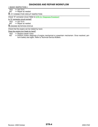
SERVICE DATA AND SPECIFICATIONS (SDS)
A
SERVICE DATA AND SPECIFICATIONS (SDS)
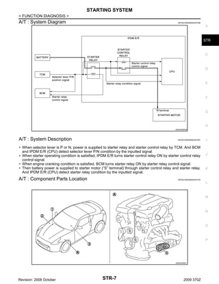
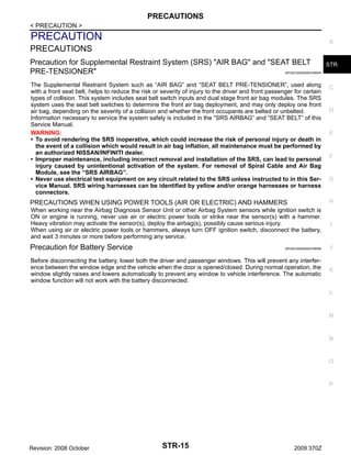
Starter Motor
INFOID:0000000004457494
S114-932
Type
STR
C
HITACHI make
Reduction gear type
System voltage
12
Terminal voltage
No-load
[V]
[V]
11
Current
[A]
Less than 110
Revolution
[rpm]
D
E
More than 2,700
Minimum diameter of commutator
[mm (in)]
28.0 (1.102)
Minimum length of brush
[mm (in)]
10.5 (0.413)
Brush spring tension
[N (kg, lb)]
Clearance between bearing metal and armature shaft
[mm (in)]
Less than 0.2 (0.008)
Clearance between pinion front edge and pinion stopper
[mm (in)]
F
16.2 (1.65, 3.6)
0.3 - 2.5 (0.012 ﻗ 0.098)
G
H
I
J
K
L
M
N
O
P
Revision: 2008 October
STR-21
2009 370Z](https://image.slidesharecdn.com/str-140302061358-phpapp01/85/Str-21-320.jpg)
Str
- 1. ENGINE SECTION STR STARTING SYSTEM A STR C D E CONTENTS BASIC INSPECTION ................................... 2 . DIAGNOSIS AND REPAIR WORKFLOW ......... 2 . STARTING SYSTEM ......................................... 14 F Symptom Table ......................................................14 . Work Flow ................................................................ 2 . PRECAUTION ............................................. 15 . FUNCTION DIAGNOSIS .............................. 5 . PRECAUTIONS ................................................. 15 STARTING SYSTEM .......................................... 5 . M/T .............................................................................. 5 . M/T : System Diagram ............................................. 5 . M/T : System Description ......................................... 5 . M/T : Component Parts Location ............................. 6 . M/T : Component Description .................................. 6 . A/T .............................................................................. 6 . A/T : System Diagram .............................................. 7 . A/T : System Description .......................................... 7 . A/T : Component Parts Location .............................. 7 . A/T : Component Description .................................. 8 . COMPONENT DIAGNOSIS ......................... 9 . B TERMINAL CIRCUIT ...................................... 9 . Description ............................................................... 9 . Diagnosis Procedure ................................................ 9 . S CONNECTOR CIRCUIT .................................10 . Description ............................................................. 10 . Diagnosis Procedure .............................................. 10 . STARTING SYSTEM .........................................11 . Wiring Diagram - STARTING SYSTEM - ............... 11 . SYMPTOM DIAGNOSIS ............................. 14 . Precaution for Supplemental Restraint System (SRS) "AIR BAG" and "SEAT BELT PRE-TENSIONER" ................................................................15 . Precaution for Battery Service ................................15 . PREPARATION .......................................... 16 . G H I PREPARATION ................................................. 16 Special Service Tools .............................................16 . Commercial Service Tools ......................................16 . ON-VEHICLE REPAIR ................................ 17 . J K STARTER MOTOR ........................................... 17 Exploded View ........................................................17 . L M/T ............................................................................18 . M/T : Removal and Installation ...............................18 . A/T .............................................................................19 . A/T : Removal and Installation ................................19 . Inspection ...............................................................20 . SERVICE DATA AND SPECIFICATIONS (SDS) ........................................................... 21 . SERVICE DATA AND SPECIFICATIONS (SDS) ................................................................. 21 M N O Starter Motor ..........................................................21 . P Revision: 2008 October STR-1 2009 370Z
- 2. DIAGNOSIS AND REPAIR WORKFLOW < BASIC INSPECTION > BASIC INSPECTION DIAGNOSIS AND REPAIR WORKFLOW Work Flow INFOID:0000000004457472 OVERALL SEQUENCE JSBIA0022GB DETAILED FLOW Revision: 2008 October STR-2 2009 370Z
- 3. DIAGNOSIS AND REPAIR WORKFLOW < BASIC INSPECTION > NOTE: To ensure a complete and thorough diagnosis, the battery, starter motor and alternator test segments must be done as a set from start to finish. A 1.DIAGNOSIS WITH STARTING/CHARGING SYSTEM TESTER Perform the starting system test with Starting/Charging System Tester (SST: J-44373). For details and operat- STR ing instructions, refer to Technical Service Bulletin. Test result C CRANKING VOLTAGE NORMAL>>GO TO 2. CRANKING VOLTAGE LOW>>GO TO 5. CHARGE BATTERY>>Perform the slow battery charging procedure. (Initial rate of charge is 10A for 12 D hours.) Perform battery test again. Refer to Technical Service Bulletin. REPLACE BATTERY>>Before replacing battery, clean the battery cable clamps and battery posts. Perform battery test again. Refer to Technical Service Bulletin. If second test result is ﻗREPLACE BATTERYﻗ, then do so. Perform battery test again to confirm repair. E CRANKING CHECK 2. Check that the starter motor operates correctly. Does the engine crank normally? YES >> GO TO 3. NO >> GO TO 4. F G 3.ENGINE START CHECK Check that the engine starts. Does the engine start? YES >> Starter motor is OK. INSPECTION END NO >> Starter motor is OK. Perform further diagnosis of engine mechanical or engine control system. Refer EM and EC sections. Once resolved, perform battery test again. 4.STARTER MOTOR ACTIVATION Check that the starter motor operates. Does the starter motor turn? YES >> Check ring gear and starter motor drive pinion. Once resolved, perform battery test again. NO >> GO TO 7. 5.COMPARISON BETWEEN ENGINE COOLANT AND CRANKING VOLTAGE H I J K Compare the engine coolant temperature and the cranking voltage with the specifications. L Minimum Specification of Cranking Voltage Referencing Coolant Temperature Engine coolant temperature [ﺡﺍC (ﺡﺍF)] Voltage [V] ﻗ30 to ﻗ20 (ﻗ22 to ﻗ4) 8.6 ﻗ19 to ﻗ10 (ﻗ2 to 14) 9.1 ﻗ9 to 0 (16 to 32) 9.5 More than 1 (More than 34) 9.9 M N Is the voltage less than the specified value? YES >> GO TO 7. NO >> GO TO 6. O 6.STARTER OPERATION Check the starter operation status. Does the starter motor turn smoothly? YES >> Starter motor is OK. INSPECTION END NO >> GO TO 7. P 7.ﻗBﻗ TERMINAL CIRCUIT INSPECTION Check ﻗBﻗ terminal circuit. Refer to STR-9, "Diagnosis Procedure". Is ﻗBﻗ terminal circuit normal? Revision: 2008 October STR-3 2009 370Z
- 4. DIAGNOSIS AND REPAIR WORKFLOW < BASIC INSPECTION > YES >> GO TO 8. NO >> Repair as needed. 8.ﻗSﻗ CONNECTOR CIRCUIT INSPECTION Check ﻗSﻗ connector circuit. Refer to STR-10, "Diagnosis Procedure". Is ﻗSﻗ connector circuit normal? YES >> GO TO 9. NO >> Repair as needed. 9.ENGINE ROTATION STATUS Check that the engine can be rotated by hand. Does the engine turn freely by hand? YES >> Replace starter motor. NO >> Perform further diagnosis of engine mechanical or powertrain mechanism. Once resolved, perform battery test again. Refer to Technical Service Bulletin. Revision: 2008 October STR-4 2009 370Z
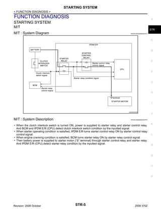
- 5. STARTING SYSTEM < FUNCTION DIAGNOSIS > FUNCTION DIAGNOSIS A STARTING SYSTEM M/T STR M/T : System Diagram INFOID:0000000004457473 C D E F G H I JSMIA0095GB M/T : System Description J INFOID:0000000004457474 ﻗ۱ When the clutch interlock switch is turned ON, power is supplied to starter relay and starter control relay. And BCM and IPDM E/R (CPU) detect clutch interlock switch condition by the inputted signal. ﻗ۱ When starter operating condition is satisfied, IPDM E/R turns starter control relay ON by starter control relay control signal. ﻗ۱ When engine cranking condition is satisfied, BCM turns starter relay ON by starter relay control signal. ﻗ۱ Then battery power is supplied to starter motor (ﻗSﻗ terminal) through starter control relay and starter relay. And IPDM E/R (CPU) detect starter relay condition by the inputted signal. K L M N O P Revision: 2008 October STR-5 2009 370Z
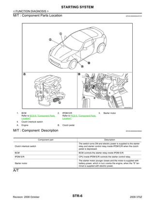
- 6. STARTING SYSTEM < FUNCTION DIAGNOSIS > M/T : Component Parts Location INFOID:0000000004457475 JSBIA0038ZZ BCM Refer to BCS-8, "Component Parts Location". 4. Engine IPDM E/R Refer to PCS-5, "Component Parts Location". 3. Starter motor Clutch pedal Clutch interlock switch A. 2. B. 1. M/T : Component Description INFOID:0000000004458493 Component part Description Clutch interlock switch The switch turns ON and electric power is supplied to the starter relay and starter control relay inside IPDM E/R when the clutch pedal is depressed. BCM BCM controls the starter relay inside IPDM E/R. IPDM E/R CPU inside IPDM E/R controls the starter control relay. Starter motor The starter motor plunger closes and the motor is supplied with battery power, which in turn cranks the engine, when the ﻗSﻗ terminal is supplied with electric power. A/T Revision: 2008 October STR-6 2009 370Z
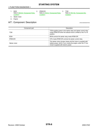
- 7. STARTING SYSTEM < FUNCTION DIAGNOSIS > A/T : System Diagram INFOID:0000000004457498 A STR C D E F G H JSMIA0096GB A/T : System Description INFOID:0000000004457497 ﻗ۱ When selector lever is P or N, power is supplied to starter relay and starter control relay by TCM. And BCM and IPDM E/R (CPU) detect selector lever P/N condition by the inputted signal. ﻗ۱ When starter operating condition is satisfied, IPDM E/R turns starter control relay ON by starter control relay control signal. ﻗ۱ When engine cranking condition is satisfied, BCM turns starter relay ON by starter relay control signal. ﻗ۱ Then battery power is supplied to starter motor (ﻗSﻗ terminal) through starter control relay and starter relay. And IPDM E/R (CPU) detect starter relay condition by the inputted signal. A/T : Component Parts Location I J K INFOID:0000000004457476 L M N O P JSBIA0039ZZ Revision: 2008 October STR-7 2009 370Z
- 8. STARTING SYSTEM < FUNCTION DIAGNOSIS > 1. BCM Refer to BCS-8, "Component Parts Location". 4. IPDM E/R Refer to PCS-5, "Component Parts Location". 3. TCM Refer to TM-142, "Component Description". Starter motor A. 2. Engine A/T : Component Description INFOID:0000000004457496 Component part Description TCM TCM supplies power to the starter relay and starter control relay inside IPDM E/R when the selector lever is shifted to the P or N position. BCM BCM controls the starter relay inside IPDM E/R. IPDM E/R CPU inside IPDM E/R controls the starter control relay. Starter motor The starter motor plunger closes and the motor is supplied with battery power, which in turn cranks the engine, when the ﻗSﻗ terminal is supplied with electric power. Revision: 2008 October STR-8 2009 370Z
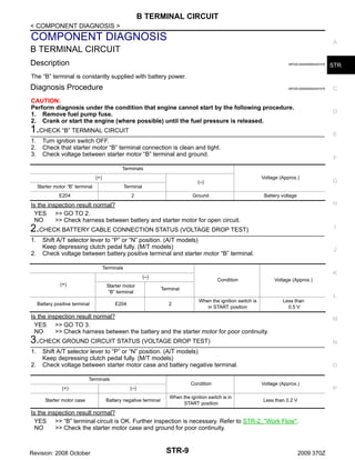
- 9. B TERMINAL CIRCUIT < COMPONENT DIAGNOSIS > COMPONENT DIAGNOSIS A B TERMINAL CIRCUIT Description INFOID:0000000004457478 STR INFOID:0000000004457479 C The ﻗBﻗ terminal is constantly supplied with battery power. Diagnosis Procedure CAUTION: Perform diagnosis under the condition that engine cannot start by the following procedure. 1. Remove fuel pump fuse. 2. Crank or start the engine (where possible) until the fuel pressure is released. D 1.CHECK ﻗBﻗ TERMINAL CIRCUIT 1. 2. 3. E Turn ignition switch OFF. Check that starter motor ﻗBﻗ terminal connection is clean and tight. Check voltage between starter motor ﻗBﻗ terminal and ground. F Terminals (+) Starter motor ﻗBﻗ terminal Terminal E204 Voltage (Approx.) (ﻗ) 2 Ground G Battery voltage Is the inspection result normal? YES >> GO TO 2. NO >> Check harness between battery and starter motor for open circuit. H 2.CHECK BATTERY CABLE CONNECTION STATUS (VOLTAGE DROP TEST) I 1. 2. Shift A/T selector lever to ﻗPﻗ or ﻗNﻗ position. (A/T models) Keep depressing clutch pedal fully. (M/T models) Check voltage between battery positive terminal and starter motor ﻗBﻗ terminal. J Terminals K (ﻗ) Condition (+) Starter motor ﻗBﻗ terminal E204 2 When the ignition switch is in START position Less than 0.5 V Terminal Battery positive terminal Voltage (Approx.) L Is the inspection result normal? YES >> GO TO 3. NO >> Check harness between the battery and the starter motor for poor continuity. M 3.CHECK GROUND CIRCUIT STATUS (VOLTAGE DROP TEST) 1. 2. N Shift A/T selector lever to ﻗPﻗ or ﻗNﻗ position. (A/T models) Keep depressing clutch pedal fully. (M/T models) Check voltage between starter motor case and battery negative terminal. Terminals (+) Starter motor case Condition Voltage (Approx.) When the ignition switch is in START position Less than 0.2 V (ﻗ) Battery negative terminal O Is the inspection result normal? YES >> ﻗBﻗ terminal circuit is OK. Further inspection is necessary. Refer to STR-2, "Work Flow". NO >> Check the starter motor case and ground for poor continuity. Revision: 2008 October STR-9 2009 370Z P
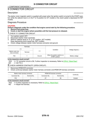
- 10. S CONNECTOR CIRCUIT < COMPONENT DIAGNOSIS > S CONNECTOR CIRCUIT Description INFOID:0000000004457480 The starter motor magnetic switch is supplied with power when the ignition switch is turned to the START position while the selector lever is in the P or N position for A/T models or the clutch pedal is depressed for M/T models. Diagnosis Procedure INFOID:0000000004457481 CAUTION: Perform diagnosis under the condition that engine cannot start by the following procedure. 1. Remove fuel pump fuse. 2. Crank or start the engine (where possible) until the fuel pressure is released. 1.CHECK ﻗSﻗ CONNECTOR CIRCUIT 1. 2. 3. 4. Turn ignition switch OFF. Disconnect starter motor connector. Shift A/T selector lever to ﻗPﻗ or ﻗNﻗ position. (A/T models) Keep depressing clutch pedal fully. (M/T models) Check voltage between starter motor harness connector and ground. Terminals (+) Starter motor harness connector Terminal F52 Condition Voltage (Approx.) When the ignition switch is in START position Battery voltage (ﻗ) 1 Ground Is the inspection result normal? YES >> ﻗSﻗ connector circuit is OK. Further inspection is necessary. Refer to STR-2, "Work Flow". NO >> GO TO 2. 2.CHECK HARNESS CONTINUITY (OPEN CIRCUIT) 1. 2. Disconnect IPDM E/R connector. Check continuity between starter motor harness connector and IPDM E/R harness connector. Starter motor harness connector IPDM E/R harness connector Connector No. Terminal No. Connector No. Terminal No. F52 1 E7 80 Continuity Existed Is the inspection result normal? YES >> Further inspection is necessary. Refer to STR-2, "Work Flow". NO >> Repair the harness. Revision: 2008 October STR-10 2009 370Z
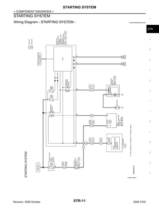
- 11. STARTING SYSTEM < COMPONENT DIAGNOSIS > STARTING SYSTEM A Wiring Diagram - STARTING SYSTEM - INFOID:0000000004457482 STR C D E F G H I J K L M N O P JCBWA1064GB Revision: 2008 October STR-11 2009 370Z
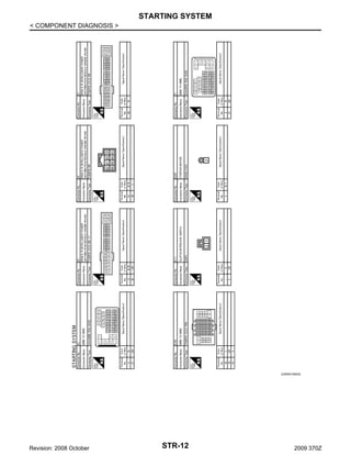
- 12. STARTING SYSTEM < COMPONENT DIAGNOSIS > JCBWA1065GB Revision: 2008 October STR-12 2009 370Z
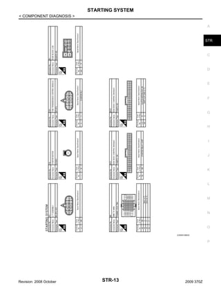
- 13. STARTING SYSTEM < COMPONENT DIAGNOSIS > A STR C D E F G H I J K L M N O JCBWA1066GB P Revision: 2008 October STR-13 2009 370Z
- 14. STARTING SYSTEM < SYMPTOM DIAGNOSIS > SYMPTOM DIAGNOSIS STARTING SYSTEM Symptom Table INFOID:0000000004457483 Symptom No normal cranking Starter motor does not rotate Revision: 2008 October Reference Refer to STR-2, "Work Flow". STR-14 2009 370Z
- 15. PRECAUTIONS < PRECAUTION > PRECAUTION A PRECAUTIONS Precaution for Supplemental Restraint System (SRS) "AIR BAG" and "SEAT BELT PRE-TENSIONER" STR INFOID:0000000004769555 The Supplemental Restraint System such as ﻗAIR BAGﻗ and ﻗSEAT BELT PRE-TENSIONERﻗ, used along with a front seat belt, helps to reduce the risk or severity of injury to the driver and front passenger for certain types of collision. This system includes seat belt switch inputs and dual stage front air bag modules. The SRS system uses the seat belt switches to determine the front air bag deployment, and may only deploy one front air bag, depending on the severity of a collision and whether the front occupants are belted or unbelted. Information necessary to service the system safely is included in the ﻗSRS AIRBAGﻗ and ﻗSEAT BELTﻗ of this Service Manual. WARNING: ﻗ۱ To avoid rendering the SRS inoperative, which could increase the risk of personal injury or death in the event of a collision which would result in air bag inflation, all maintenance must be performed by an authorized NISSAN/INFINITI dealer. ﻗ۱ Improper maintenance, including incorrect removal and installation of the SRS, can lead to personal injury caused by unintentional activation of the system. For removal of Spiral Cable and Air Bag Module, see the ﻗSRS AIRBAGﻗ. ﻗ۱ Never use electrical test equipment on any circuit related to the SRS unless instructed to in this Service Manual. SRS wiring harnesses can be identified by yellow and/or orange harnesses or harness connectors. C D E F G PRECAUTIONS WHEN USING POWER TOOLS (AIR OR ELECTRIC) AND HAMMERS H When working near the Airbag Diagnosis Sensor Unit or other Airbag System sensors while ignition switch is ON or engine is running, never use air or electric power tools or strike near the sensor(s) with a hammer. Heavy vibration may activate the sensor(s), deploy the airbag(s), possibly cause serious injury. When using air or electric power tools or hammers, always turn OFF ignition switch, disconnect the battery, and wait 3 minutes or more before performing any service. I Precaution for Battery Service J INFOID:0000000004769556 Before disconnecting the battery, lower both the driver and passenger windows. This will prevent any interference between the window edge and the vehicle when the door is opened/closed. During normal operation, the window slightly raises and lowers automatically to prevent any window to vehicle interference. The automatic window function will not work with the battery disconnected. K L M N O P Revision: 2008 October STR-15 2009 370Z
- 16. PREPARATION < PREPARATION > PREPARATION PREPARATION Special Service Tools INFOID:0000000004457485 Tool number (Kent-Moore No.) Tool name Description ﻗ (J-44373 Model MCR620) Starting/Charging System Tester SEL403X Tests starting and charging systems. For operating instructions, refer to Technical Service Bulletin. Commercial Service Tools INFOID:0000000004457486 Tool name Description Power tool Loosening bolts, nuts and screws PIIB1407E Revision: 2008 October STR-16 2009 370Z
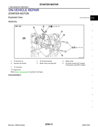
- 17. STARTER MOTOR < ON-VEHICLE REPAIR > ON-VEHICLE REPAIR A STARTER MOTOR Exploded View INFOID:0000000004457487 STR REMOVAL C D E F G H JPBIA0147GB 1. ﻗBﻗ terminal nut 2. ﻗBﻗ terminal harness 3. Starter motor 4. Harness clip bracket 5. Starter motor mounting bolt 6. Converter housing (A/T models) Transmission case (M/T models) 7. ﻗSﻗ connector I J : Engine front Refer to GI-4, "Components" for symbols in the figure. DISASSEMBLY K L M N O P Revision: 2008 October STR-17 2009 370Z
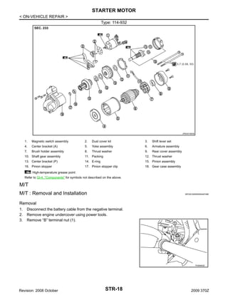
- 18. STARTER MOTOR < ON-VEHICLE REPAIR > Type: 114-932 JPBIA0148GB 1. Magnetic switch assembly 2. Dust cover kit 3. Shift lever set 4. Center bracket (A) 5. Yoke assembly 6. Armature assembly 7. Brush holder assembly 8. Thrust washer 9. Rear cover assembly 10. Shaft gear assembly 11. Packing 12. Thrust washer 13. Center bracket (P) 14. E-ring 15. Pinion assembly 16. Pinion stopper 17. Pinion stopper clip 18. Gear case assembly : High-temperature grease point Refer to GI-4, "Components" for symbols not described on the above. M/T M/T : Removal and Installation INFOID:0000000004457488 Removal 1. 2. 3. Disconnect the battery cable from the negative terminal. Remove engine undercover using power tools. Remove ﻗBﻗ terminal nut (1). PKIB8802E Revision: 2008 October STR-18 2009 370Z
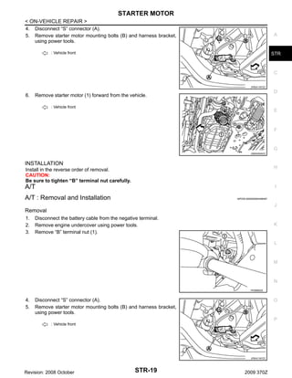
- 19. STARTER MOTOR < ON-VEHICLE REPAIR > 4. Disconnect ﻗSﻗ connector (A). 5. Remove starter motor mounting bolts (B) and harness bracket, using power tools. A : Vehicle front STR C JPBIA1187ZZ 6. D Remove starter motor (1) forward from the vehicle. : Vehicle front E F G JSBIA0040ZZ INSTALLATION Install in the reverse order of removal. CAUTION: Be sure to tighten ﻗBﻗ terminal nut carefully. H A/T I A/T : Removal and Installation INFOID:0000000004458487 J Removal 1. 2. 3. Disconnect the battery cable from the negative terminal. Remove engine undercover using power tools. Remove ﻗBﻗ terminal nut (1). K L M N PKIB8802E 4. 5. Disconnect ﻗSﻗ connector (A). Remove starter motor mounting bolts (B) and harness bracket, using power tools. O P : Vehicle front JPBIA1187ZZ Revision: 2008 October STR-19 2009 370Z
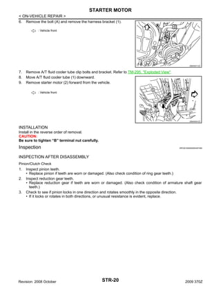
- 20. STARTER MOTOR < ON-VEHICLE REPAIR > 6. Remove the bolt (A) and remove the harness bracket (1). : Vehicle front JSBIA0011ZZ 7. 8. 9. Remove A/T fluid cooler tube clip bolts and bracket. Refer to TM-295, "Exploded View". Move A/T fluid cooler tube (1) downward. Remove starter motor (2) forward from the vehicle. : Vehicle front JSBIA0041ZZ INSTALLATION Install in the reverse order of removal. CAUTION: Be sure to tighten ﻗBﻗ terminal nut carefully. Inspection INFOID:0000000004457490 INSPECTION AFTER DISASSEMBLY Pinion/Clutch Check 1. 2. 3. Inspect pinion teeth. ﻗ۱ Replace pinion if teeth are worn or damaged. (Also check condition of ring gear teeth.) Inspect reduction gear teeth. ﻗ۱ Replace reduction gear if teeth are worn or damaged. (Also check condition of armature shaft gear teeth.) Check to see if pinion locks in one direction and rotates smoothly in the opposite direction. ﻗ۱ If it locks or rotates in both directions, or unusual resistance is evident, replace. Revision: 2008 October STR-20 2009 370Z
- 21. SERVICE DATA AND SPECIFICATIONS (SDS) < SERVICE DATA AND SPECIFICATIONS (SDS) SERVICE DATA AND SPECIFICATIONS (SDS) A SERVICE DATA AND SPECIFICATIONS (SDS) Starter Motor INFOID:0000000004457494 S114-932 Type STR C HITACHI make Reduction gear type System voltage 12 Terminal voltage No-load [V] [V] 11 Current [A] Less than 110 Revolution [rpm] D E More than 2,700 Minimum diameter of commutator [mm (in)] 28.0 (1.102) Minimum length of brush [mm (in)] 10.5 (0.413) Brush spring tension [N (kg, lb)] Clearance between bearing metal and armature shaft [mm (in)] Less than 0.2 (0.008) Clearance between pinion front edge and pinion stopper [mm (in)] F 16.2 (1.65, 3.6) 0.3 - 2.5 (0.012 ﻗ 0.098) G H I J K L M N O P Revision: 2008 October STR-21 2009 370Z