Subnet Design
ŌĆóDownload as DOCX, PDFŌĆó
2 likesŌĆó2,072 views

IPv4 uses 32-bit addresses which limits the address space to around 4 billion addresses. It allocates addresses into classes (A, B, C) but this led to inefficient allocation. Subnetting and CIDR were developed to allow more flexible allocation of addresses and reduce routing table sizes. Subnetting divides classes into smaller subnets, while CIDR ignores classes and allows allocation on any bit boundary. This helped slow the growth of routing tables and address exhaustion.


Subnet Design
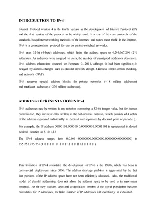
- 1. INTRODUCTION TO IPv4 Internet Protocol version 4 is the fourth version in the development of Internet Protocol (IP) and the first version of the protocol to be widely used. It is one of the core protocols of the standards-based internetworking methods of the Internet, and routes most traffic in the Internet. IPv4 is a connectionless protocol for use on packet-switched networks. IPv4 uses 32-bit (4-byte) addresses, which limits the address space to 4,294,967,296 (232) addresses. As addresses were assigned to users, the number of unassigned addresses decreased. IPv4 address exhaustion occurred on February 3, 2011, although it had been significantly delayed by address changes such as classful network design, Classless Inter-Domain Routing, and network (NAT). IPv4 reserves special address blocks for private networks (~18 million addresses) and multicast addresses (~270 million addresses). ADDRESS REPRESENTATIONIN IPv4 IPv4 addresses may be written in any notation expressing a 32-bit integer value, but for human convenience, they are most often written in the dot-decimal notation, which consists of 4 octets of the address expressed individually in decimal and separated by decimal point or periods (.). For example, the IP address 00000101.00001010.00000001.00001101 is represented in dotted decimal notation as 5.10.1.13 The IPv4 address ranges from 0.0.0.0 (00000000.00000000.00000000.00000000) to 255.255.255.255 (11111111.11111111.11111111.11111111). This limitation of IPv4 stimulated the development of IPv6 in the 1990s, which has been in commercial deployment since 2006. The address shortage problem is aggravated by the fact that portions of the IP address space have not been efficiently allocated. Also, the traditional model of classful addressing does not allow the address space to be used to its maximum potential. As the new markets open and a significant portion of the world population become candidates for IP addresses, the finite number of IP addresses will eventually be exhausted.
- 2. In order to provide the flexibility required to support different size networks, the designers decide to divide the IP address space into different address classes ŌĆō Class A, Class B and Class C. this is often referred to as ŌĆśclassfulŌĆÖ addressing because the address space is split into 3 predefined classes, groupings or categories. Each class fixes the boundary between the network-prefix and host-number at a different point within the 32-bit address. One of the fundamental features of classful IP addressing is that each address contains a self- encoding key that identifies the dividing point between the network-prefix and the host- number. Class A Networks (/8 prefixes) Each Class A network address has an 8-bit network-prefix with the MSB set to 0 and a 7-bit network number, followed by a 24-bit host-number. Class A networks are referred to as ŌĆś/8ŌĆÖ since they have an 8-bit network-prefix. A maximum of 126 (27 ŌĆō 2) /8 networks can be defined. 2 is subtracted from 27 because the address 0.0.0.0 has been reserved for use as the d default route and the address 127.0.0.0 has been reserved for ŌĆśloopbackŌĆÖ function. Maximum number of hosts per network in /8 is 224 ŌĆō 2. IP address range is from 0.0.0.0 to 127.255.255.255, where 0.0.0.0 is the IP address of the network itself and 127.255.255.255 is used for broadcasting purpose. Class B Networks (/16 prefixes) Each Class B network address has a 16-bit network-prefix with the first 2 highest order bits set to 10 and a 14-bit network number, followed by a 16-bit host-number. Class B networks are referred to as ŌĆś/16ŌĆÖ since they have a 16-bit network-prefix. A maximum of 16,384 (214) /16 networks can be defined. Maximum number of hosts per network in /16 is 216 ŌĆō 2. IP address range is from 128.0.0.0 to 191.255.255.255, where 128.0.0.0 is the IP address of the network itself and 191.255.255.255 is used for broadcasting purpose. Class C Networks (/24 prefixes) Each Class C network address has a 24-bit network-prefix with the first 3 highest order bits set to 110 and a 21-bit network number, followed by an 8-bit host-number. Class C networks are referred to as ŌĆś/24ŌĆÖ since they have a 24-bit network-prefix. A maximum of 221 /24 networks can be defined. Maximum number of hosts per network in /24 is 254 (28 ŌĆō 2). IP address range is from 192.0.0.0 to 223.255.255.255, where 192.0.0.0 is the IP address of the network itself and 223.255.255.255 is used for broadcasting purpose.
- 3. There is also a Class D network which is used for multicasting and a Class E network for research purposes and future use. SUBNETTING Subnetting and Supernetting are the techniques used to make up for the shortage of IP addresses. Subnetting is the procedure of dividing a single Class A, B or C network into smaller pieces. Subnetting was introduced to overcome some of the problems that parts of the Internet were beginning to experience with the classful 2-level addressing hierarchy. Subnetting attacked the expanding routing table problem by ensuring that the subnet structure of a network is never visible outside of the organizationŌĆÖs private network. The route from the Internet to any subnet of a given IP address is the same, no matter which subnet the destination host is on. This is because all subnets of a given network use the same network-prefix but different subnet numbers. The routers within the private organization are collected into a single routing table entry. This allows the local administrator to introduce arbitrary complexity into the private network without affecting the size of InternetŌĆÖs routing tables. Subnetting overcame the registered number issue by assigning each organization one (or at most a few) network number(s) from the IPv4 address space. The organization is then free to assign a distinct subnet number for each of its internal networks. There are two types of subnetting used: 1. Variable Length Subnet Mask (VLSM) 2. Classless Inter Domain Routing (CIDR) A subnet mask is denoted as <IP address>/n, where ŌĆśnŌĆÖ denotes the number of bits used to identify the type of network. Rules to write Subnet Mask: ŌĆśnŌĆÖ bits from the MSB end is set to 1 and the remaining (32 ŌĆō n) bits are set to 0, and then it is written in dotted-decimal format. For Class A, default subnet mask is /8 i.e. 11111111.00000000.00000000.00000000, which when written in dotted-decimal gives 255.0.0.0.
- 4. For Class B, default subnet mask is /16 i.e. 11111111.11111111.00000000.00000000, which when written in dotted-decimal gives 255.255.0.0. For Class C, default subnet mask is /24 i.e. 11111111.11111111.11111111.00000000, which when written in dotted-decimal gives 255.255.255.0. The standards describing modern routing protocols often refer to the extended network-prefix length rather than the subnet mask. The prefix length is equal to the number contiguous 1-bits in the traditional subnet mask. This means that specifying a network address 130.5.5.25 with a subnet mask of 255.255.255.0 can also be expressed as 130.5.5.25/24. The /<prefix-length> notation is more compact and easier to understand than writing out the mask in its traditional dotted-decimal format. 1. CLASSLESS INTER DOMAIN ROUTING (CIDR) Classless Inter-Domain Routing (CIDR) is a method for allocating IP addresses and routing Internet Protocol packets. The Internet Engineering Task Force (IETF) introduced CIDR in 1993 to replace the previous addressing architecture of classful network design in the Internet. Its goal was to slow the growth of routing tables on routers across the Internet, and to help slow the rapid exhaustion of IPv4 addresses. Classful network design for IPv4 sized the network address as one or more 8-bit groups, resulting in the blocks of Class A, B or C addresses. Classless Inter-Domain Routing allocates address space to Internet Service Providers (ISPs) and end users on any address bit boundary, instead of on 8-bit segments. CIDR eliminates the traditional concept of Class A, B and C network addresses, and supports route aggregation where a single routing table entry can represent the address space of perhaps thousands of traditional classful routers. Route aggregation helps control the amount of routing information in the InternetŌĆÖs backbone routers, reduces route flapping (rapid changes in route availability), and eases the local administrative burden of updating external routing information. Without the rapid deployment of CIDR in 1994 and 1995, the Internet routing tables would have in excess of 70,000 routes (instead of the current 30,000+) and the Internet would probably not be functioning today.
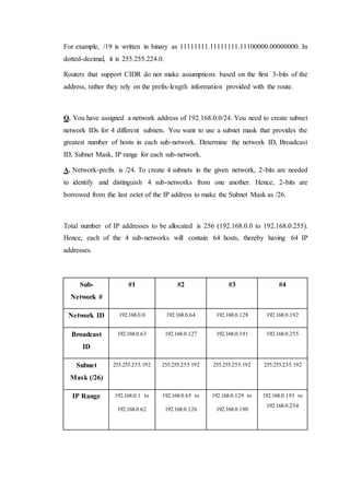
- 5. For example, /19 is written in binary as 11111111.11111111.11100000.00000000. In dotted-decimal, it is 255.255.224.0. Routers that support CIDR do not make assumptions based on the first 3-bits of the address, rather they rely on the prefix-length information provided with the route. Q. You have assigned a network address of 192.168.0.0/24. You need to create subnet network IDs for 4 different subnets. You want to use a subnet mask that provides the greatest number of hosts in each sub-network. Determine the network ID, Broadcast ID, Subnet Mask, IP range for each sub-network. A. Network-prefix is /24. To create 4 subnets in the given network, 2-bits are needed to identify and distinguish 4 sub-networks from one another. Hence, 2-bits are borrowed from the last octet of the IP address to make the Subnet Mask as /26. Total number of IP addresses to be allocated is 256 (192.168.0.0 to 192.168.0.255). Hence, each of the 4 sub-networks will contain 64 hosts, thereby having 64 IP addresses. Sub- Network # #1 #2 #3 #4 Network ID 192.168.0.0 192.168.0.64 192.168.0.128 192.168.0.192 Broadcast ID 192.168.0.63 192.168.0.127 192.168.0.191 192.168.0.255 Subnet Mask (/26) 255.255.255.192 255.255.255.192 255.255.255.192 255.255.255.192 IP Range 192.168.0.1 to 192.168.0.62 192.168.0.65 to 192.168.0.126 192.168.0.129 to 192.168.0.190 192.168.0.193 to 192.168.0.254
- 6. 2. VARIABLE LENGTH SUBNET MASKS (VLSM) 1n 1987, RFC 1009 specified how a subnet network could use more than one subnet masks. When an IP network is assigned more than one subnet masks, it is considered as a network with ŌĆśvariable length subnet masksŌĆÖ. Multiple subnet masks permit more efficient use of an organizationŌĆÖs assigned IP address space. Multiple subnet masks also permits route aggregation which can significantly reduce the amount of routing information at the ŌĆśbackboneŌĆÖ level within an organizationŌĆÖs routing domain. VLSM supports more efficient use of an organizationŌĆÖs assigned IP address space. One of the major problems with the earlier limitation of using only a single subnet mask across a given network-prefix was that once the mask was selected, it locked the organization into a fixed number of fixed sized subnets. Conceptually, a network is first divided into subnets, some of the subnets are further divided into sub-subnets, and some of the sub-subnets are further divided into sub 2- nets. This allows the detailed structure of routing information for one subnet group to be hidden from routers in another subnet group. Q. For a Class C network 202.195.32.0 assigned to ISP. Determine the network ID, broadcast ID, subnet mask & IP range for each sub-network from the given topology.
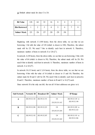
- 7. A. Default subnet mask for class C is /24. Bit Value 128 64 32 16 8 4 2 1 Bits Borrowed 1 2 3 4 5 6 7 8 Subnet Mask /25 /26 /27 /28 /29 /30 Beginning with network E (100 hosts), from the above table, we see that we are borrowing 1 bit with the value of 128 (which is closest to 100). Therefore, the subnet mask will be /25. We need 7 bits to identify each host in network E. Therefore, maximum number of hosts in network E is 128 (27). In network A (50 hosts), from the above table, we see that we are borrowing 2 bits with the value of 64 (which is closest to 50). Therefore, the subnet mask will be /26. We need 6 bits to identify each host in network A. Therefore, maximum number of hosts in network A is 64 (26). In network B (13 hosts) and C (14 hosts), from the above table, we see that we are borrowing 4 bits with the value of 16 (which is closest to 13 and 14). Therefore, the subnet mask for B and C will be /28. We need 4 bits to identify each host in networks B and C. Therefore, maximum number of hosts in B and C is 16 (24) each. Since network D is the only one left, the rest all 16 host addresses are given to it. Sub-Network Network ID Broadcast ID Subnet Mask IP Range A 202.195.32.128 202.195.32.191 /26 255.255.255.192 202.195.32.129 to 202.195.32.190 B 202.195.32.208 202.195.32.223 /28 255.255.255.240 202.195.32.209 to 202.195.32.222 C 202.195.32.192 202.195.32.207 /28 255.255.255.240 202.195.32.193 to 202.195.32.206
- 8. D 202.195.32.224 202.195.32.239 /28 255.255.255.240 202.195.32.225 to 202.195.32.238 E 202.195.32.0 202.195.32.127 /25 255.255.255.128 202.195.32.1 to 202.195.32.127 CONCLUSION Therefore, it is seen that by using subnetting and its different techniques, we are able to use IPv4 addresses. But once they are totally exhausted, then we will be deployed to 128-bit IPv6, which is far more reliable and has a very large IP address space as compared to the address space of IPv4. --x--