SUMMER INTERNSHIP PROGRAM.docx
- 1. SUMMER INTERNSHIP PROGRAM MACHINE SHOP DIVISION AT UFLEX GUJARAT TECHNOLOGICAL UNIVERSITY INDUSTRIAL INTERSHIP PROGRAM REPORT OF BACHELOR OF ENGINEERING IN MECHNICAL ENGINEERING 2018-22 SUBMITTED BY GAURAV KUMAR BHATT ROLL NO:181420119007 COMPANY MENTOR FACULTY MENTOR MR. RAVI SHANKAR PANDAY MR. PUSHPRAJ JIWNAPURKAR DEPUTY GENERAL MANAGER ASSISTANT PROFESSOR GOVERNMENT ENGINEERING COLLEGE, DAMAN
- 2. 2 Summer Internship (machine shop) at Uflex Ltd. Index table 1 Company profile 2 5m Of Machine Shop: 3 Machines At Machine Shop: 4 Processing of raw material ˇú Product ˇú Dispatch: 5 Manufacturing 6 Drawing 7 Material 8 Measurement instrument: 9 Tool 10 Quality 11 CNC machine
- 3. 3 Summer Internship (machine shop) at Uflex Ltd. COMPANYPROFILE Established¨C 1973 Headquarter ¨C Noida Manufacturing units ¨C Noida and Dubai Established offices - UAE, Europe, and North America and enjoys a formidable market presence in more than 85 countries. U flex facility enjoys ISO 9001 and ISO 14001 certifications and has FDA and BGA approvals for their products. Itis also a part of the D&B Global Database and winner of various prestigious national and international awards like the top exporter of BOPET and BOPP films, and the World star award for packaging excellence. FPA, AIMCAL and the DUPONT Awards in 2004- 2005 are the latest in this series. Being a multi-faceted organization, it has integrated its operations from manufacture of Polyester chips, Films (BOPET, BOPP and CPP - both in plain and metalized form), Coated Film, Laminates, Pouches, Holographic films Gravure cylinders, Inks and adhesives to all types of packaging & printing machines, offering total flexible packaging solution. Over a period of time, Uflex has not only established its productsˇŻ brand in the domestic and international market, but has also setup high-tech and advance technology-based productionfacilities in the overseas. It has state of the art and world size modernfacilities, presently located in India and Dubai, accredited with ISO, BRC and HACCP certificates. Truly speaking, Uflex is the only worldˇŻs vertically integrated manufacturer of flexible plastic films. It has been awarded various prestigious national and international awards for its innovative packaging conceptand has also been enjoying IPR in the national and international market for various products. While enjoying its leadership status in domestic market for last many years, Uflex has been aiming to becomeone amongst the largest flexible plastic material producer in the world by expanding its base in the country as well as setting up green field/ brown field projects in the overseas. In addition to its organic growth, Uflex is also focusing on inorganic growth as well to grow its business aggressively in the world
- 4. 4 Summer Internship (machine shop) at Uflex Ltd. 5m Of Machine Shop: 1. Machine 2. Material 3. Manpower 4. Method Machines At Machine Shop: 1. VMC 2. CNC 3. Turning machine 4. Vertical milling 5. Horizontal milling 6. Lath machine 7. Milling (MNTR) 8. Grinding machine 9. Surface grinding 10. Planner 11.Shaper 12.Power hack saw 13.Band saw 14.Drilling 15.Laser cutter
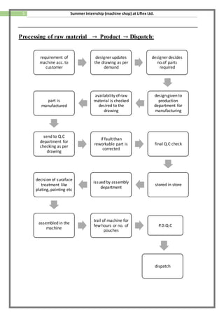
- 5. 5 Summer Internship (machine shop) at Uflex Ltd. Processing of raw material ˇú Product ˇú Dispatch: requirement of machine acc. to customer designer updates the drawing as per demand designer decides no.of parts required design given to production department for manufacturing availability of raw material is checked desired to the drawing part is manufactured send to Q.C department for checking as per drawing if fault than reworkable part is corrected final Q.C check stored in store issued by assembly department decision of suraface treatment like plating, painting etc assembled in the machine trail of machine for few hours or no. of pouches P.D.Q.C dispatch
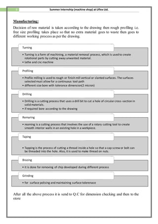
- 6. 6 Summer Internship (machine shop) at Uflex Ltd. Manufacturing: Decision of raw material is taken according to the drawing then rough profiling i.e. free size profiling takes place so that no extra material goes to waste then goes to different working process as per the drawing. After all the above process it is send to Q.C for dimension checking and then to the store ? Turning is a form of machining, a material removal process, which is used to create rotational parts by cutting away unwanted material. ? lathe and cnc machine Turning ? Profile milling is used to rough or finish mill vertical or slanted surfaces. The surfaces selected must allow for a continuous tool path ? different size bore with tolerance dimension(2 micron) Profiling ? Drilling is a cutting process that uses a drill bit to cut a hole of circular cross-section in solid materials. ? if required bore according to the drawing Drilling ? reaming is a cutting process that involves the use of a rotary cutting tool to create smooth interior walls in an existing hole in a workpiece. Remaring ? Tapping is the process of cutting a thread inside a hole so that a cap screw or bolt can be threaded into the hole. Also, it is used to make thread on nuts. Taping ? it is done for removing of chip developed during different process Brazing ? for surface polising and maintaining surface tolerenace Grinding
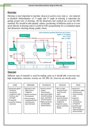
- 7. 7 Summer Internship (machine shop) at Uflex Ltd. Drawing: Drawing is most important in machine shop as is used in every step i.e. raw material to dispatch. Determination of 1st angle and 3rd angle in drawing is important for getting proper view of drawing. All the dimension and symbols are as per the ISO standard. We should be able identify relative positioning ofdifferent point as it is not given directly in drawing and it is useful in CNC programming for co-ordination input and dimension checking during quality check. Material: Different type of material is used for making parts as it should able overcome tear, high temperature, moisture, toxicity etc. SS, MS, AL, brass etc are mostly used. SS202 ?possessesgood corrosion resistance, toughness, high harness, and strength ?low grade ?usedformaking utensiles MS(SS420) ?All steel inthe 400 seriesis magnetic. ?great resistance to corrosion. ?verystrongas comparedto the normal every day mildsteel EN 29,EN 24 ?mainlyusedin power transmission gearsand shafts, aircraft landing gear,and other structural parts. ?Material bends considerably before failour. D2,D3,D4 ?D2 isa high chromiumtool steel forcold work. ?D2 has high wearresistance and moderate toughness ?Usedfor shear, planerandknife blades. SS316 ?austenitic chromium-nickel stainlessand heat-resisting steel ?superior corrosion resistance as compared ?usedforpart where food materaial getsin directcontact
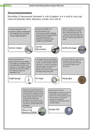
- 8. 8 Summer Internship (machine shop) at Uflex Ltd. Measurementinstrument: Knowledge of measurement instrument is sole of engineer as it is used in every step such as to determine linear dimension, circular, bore, slot etc ? Least count:0.02 mm ? vernier caliper, instrument for making very accurate linear measurements Vernier Caliper ?Leastcount:0.001 mm ?A micrometerisan instrumentusedformaking precise linearmeasurements of dimensionssuchas diameter,thickness,and lengthsof solidbodies. Vernier Micrometre ?Go/No-Go gages measure parts to ensure that they are within their specified tolerances.The ˇ°no-goˇ± portion represents one end of the tolerancerange, and the ˇ°goˇ± portion represents the other. Go/No-Go Gage ?Least count:0.02 mm ?used to determine the height of an object or workpiece with extremely high precision and accuracy, or to provide marked locations on the item relative to a reference plane for subsequent use Height gauge ?. Air gages function by shooting air out of a specifically calibrated nozzle, and recordingthe rate at which the air returns to multiple sensingnozzles.Thus, they are ableto read the air flow between the measuringtool and the object being measured. Air Gage ?it used in different slotto check if it ableto pass through itis more accuratethan a vernier scalemeasuringthe same dimension Slip gauges ?mechanical coordinatesystem with the platform of measuring machineas the reference plane, to collectthe coordinatevalues of the measured points on the surfaceof the measured workpiece, then projectit into the spatial coordinatesystemto constructa spatial model of the workpiece. Coordinate Measuring Machine (CMM) ?leastcount of 0.01mm ?Dial gauges areused to measure the flatness and inclination of objects. Itis used to check round bar roundness.It checks the flatness of an object as compared to the flatness of the standard object plunger dial
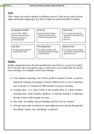
- 9. 9 Summer Internship (machine shop) at Uflex Ltd. Tool: Their various tool used in machine for different process.There are two types of tools single and double cutting-edge tool. Most of them are made from HSS or carbide. Quality: Quality department check the part manufactured part before it is used in assembly. Q.C if the part will be accepted or reject or part can be recoverable after the rework as per drawing. Few examples on Q.C part checking ? Cam: hardness mounting, size of bore, profile is checked. Vernier is used for dimension checking, bore gauge is used for different bore, as cam is important part so mostly it is checked on CMM machine for precise checking. ? Locking plate: it is used to hold to part locking them to a fixed position. mounting hole, centre distance, thickness is checked; thickness is important because it has to hold strongly two parts. ? Dye roller: for sealing of pouch. Knurling and bore size are checked ? Pressurewater tank: to checkevery aspecthigh pressureis passed through tank thus thread, volume, size, and leakage is checked. IndexableEnd Mill ?usedinCNC , MNTR ?face milling(dia:25-50) ?profilingcut, spiral bore(dia:20,16) End mill ?usedforprofile milingi.e. cleanthe surface and to make tolerace type finish Slot Cutter ?it isusedto make specific type of slotaccording to the drawing ?dia:5,6,7.. Tap Tool ?to make standardtype of tape M8, M12, M16 Threading Tool ?to make desirable sizeof threadhavingdifferenttype of pitchingarea Reamer Tool ?it isusedto make standard size of bore or hightolerance type (10 micron)
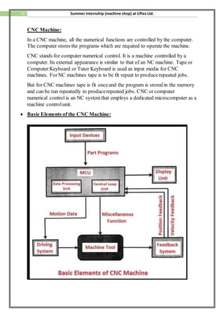
- 10. 10 Summer Internship (machine shop) at Uflex Ltd. CNC Machine: In a CNC machine, all the numerical functions are controlled by the computer. The computer stores the programs which are required to operate the machine. CNC stands for computer numerical control. It is a machine controlled by a computer. Its external appearance is similar to that of an NC machine. Tape or Computer Keyboard or Tutor Keyboard is used as input media for CNC machines. ForNC machines tape is to be fit repeat to producerepeated jobs. But for CNC machines tape is fit onceand the program is stored in the memory and can be run repeatedly to producerepeated jobs. CNC or computer numerical control is an NC system that employs a dedicated microcomputer as a machine controlunit. ? Basic Elements of the CNC Machine:
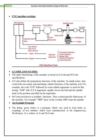
- 11. 11 Summer Internship (machine shop) at Uflex Ltd. ? CNC machine working: ? G CODE AND M CODE: ? The entire functioning of the machine is based on G Codeand M Code specifications. ? G Codes define the preparatory functions of the machine. In simple terms, they control the movement and machining related functions of the machine tool. For example, the code"G76" followed by some related arguments is used for fine boring. "G00" with X,Y,Z arguments rapidly moves the bed and the spindle head to the position specified by the arguments. ? M Codes are known as auxiliary functions. They controlspecific behaviours of the machine. For example "M08" turns on the coolant, M05 stops the spindle. ? An Example Program ? The listing given below is a program which was used to bore holes in couplings of two turbines which were manufactured in the Engineering Workshops. It is written in G and M Codes.
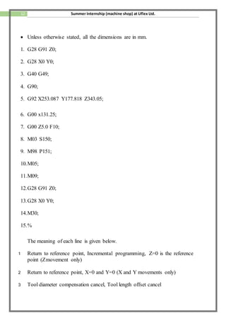
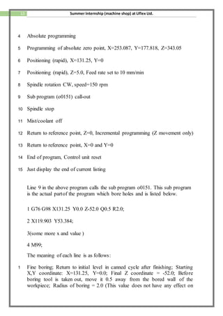
- 12. 12 Summer Internship (machine shop) at Uflex Ltd. ? Unless otherwise stated, all the dimensions are in mm. 1. G28 G91 Z0; 2. G28 X0 Y0; 3. G40 G49; 4. G90; 5. G92 X253.087 Y177.818 Z343.05; 6. G00 x131.25; 7. G00 Z5.0 F10; 8. M03 S150; 9. M98 P151; 10.M05; 11.M09; 12.G28 G91 Z0; 13.G28 X0 Y0; 14.M30; 15.% The meaning of each line is given below. 1 Return to reference point, Incremental programming, Z=0 is the reference point (Zmovement only) 2 Return to reference point, X=0 and Y=0 (X and Y movements only) 3 Tool diameter compensation cancel, Tool length offset cancel
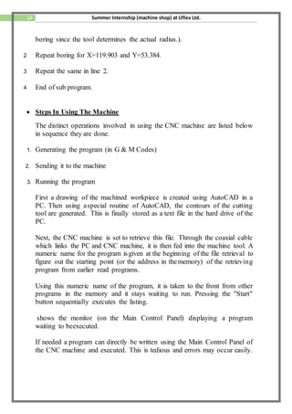
- 13. 13 Summer Internship (machine shop) at Uflex Ltd. 4 Absolute programming 5 Programming of absolute zero point, X=253.087, Y=177.818, Z=343.05 6 Positioning (rapid), X=131.25, Y=0 7 Positioning (rapid), Z=5.0, Feed rate set to 10 mm/min 8 Spindle rotation CW, speed=150 rpm 9 Sub program (o0151) call-out 10 Spindle stop 11 Mist/coolant off 12 Return to reference point, Z=0, Incremental programming (Z movement only) 13 Return to reference point, X=0 and Y=0 14 End of program, Control unit reset 15 Just display the end of current listing Line 9 in the above program calls the sub program o0151. This sub program is the actual partof the program which bore holes and is listed below. 1 G76 G98 X131.25 Y0.0 Z-52.0 Q0.5 R2.0; 2 X119.903 Y53.384; 3(some more x and value ) 4 M99; The meaning of each line is as follows: 1 Fine boring; Return to initial level in canned cycle after finishing; Starting X,Y coordinate: X=131.25, Y=0.0; Final Z coordinate = -52.0; Before boring tool is taken out, move it 0.5 away from the bored wall of the workpiece; Radius of boring = 2.0 (This value does not have any effect on
- 14. 14 Summer Internship (machine shop) at Uflex Ltd. boring since the tool determines the actual radius.). 2 Repeat boring for X=119.903 and Y=53.384. 3 Repeat the same in line 2. 4 End of sub program. ? Steps In Using The Machine The distinct operations involved in using the CNC machine are listed below in sequence they are done. 1. Generating the program (in G & M Codes) 2. Sending it to the machine 3. Running the program First a drawing of the machined workpiece is created using AutoCAD in a PC. Then using aspecial routine of AutoCAD, the contours of the cutting tool are generated. This is finally stored as a text file in the hard drive of the PC. Next, the CNC machine is set to retrieve this file. Through the coaxial cable which links the PC and CNC machine, it is then fed into the machine tool. A numeric name for the program isgiven at the beginning of the file retrieval to figure out the starting point (or the address in thememory) of the retrieving program from earlier read programs. Using this numeric name of the program, it is taken to the front from other programs in the memory and it stays waiting to run. Pressing the "Start" button sequentially executes the listing. shows the monitor (on the Main Control Panel) displaying a program waiting to beexecuted. If needed a program can directly be written using the Main Control Panel of the CNC machine and executed. This is tedious and errors may occur easily.
