Team bender
- 1. Team Members: Doug Bradley Dan Ehlke
- 2. Strain Test Stand Finite Element Analysis (FEA) vs Physical Testing School of Technology Lab Cheaply Load of up to 150 lbs Various length/geometry test specimens
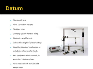
- 3. Aluminum Frame Force Application: weights Plexiglass cover Clamping system: standard clamp Electronics: amplifier unit. Data Output: Digital display of voltage Signal Conditioning: Tare function to exclude the influence of preloads. Test Specimens: tensile test rods, in aluminium, copper and brass Force measurement: manually add weight values
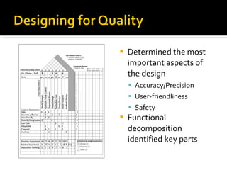
- 4. Determined the most important aspects of the design Accuracy/Precision User-friendliness Safety Functional decomposition identified key parts
- 5. ?
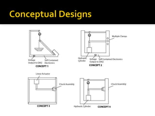
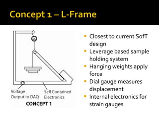
- 6. Closest to current SofT design Leverage based sample holding system Hanging weights apply force Dial gauge measures displacement Internal electronics for strain gauges
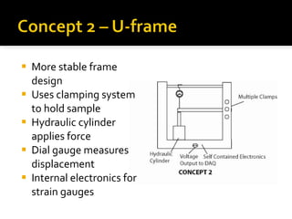
- 7. More stable frame design Uses clamping system to hold sample Hydraulic cylinder applies force Dial gauge measures displacement Internal electronics for strain gauges
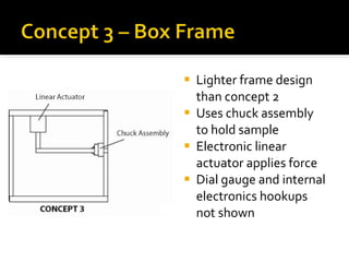
- 8. Lighter frame design than concept 2 Uses chuck assembly to hold sample Electronic linear actuator applies force Dial gauge and internal electronics hookups not shown
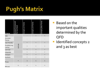
- 9. Based on the important qualities determined by the QFD Identified concepts 2 and 3 as best
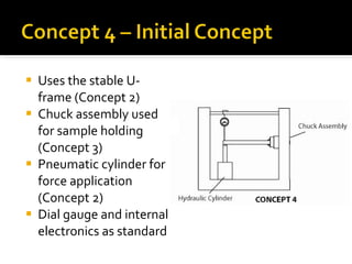
- 10. Uses the stable U-frame (Concept 2) Chuck assembly used for sample holding (Concept 3) Pneumatic cylinder for force application (Concept 2) Dial gauge and internal electronics as standard
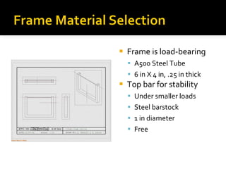
- 11. Frame is load-bearing A500 Steel Tube 6 in X 4 in, .25 in thick Top bar for stability Under smaller loads Steel barstock 1 in diameter Free
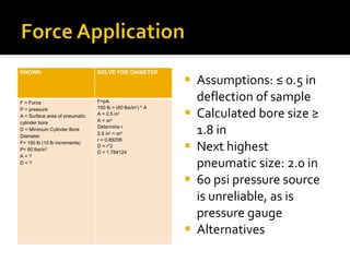
- 12. Assumptions: ˇÜ 0.5 in deflection of sample Calculated bore size ˇÝ 1.8 in Next highest pneumatic size: 2.0 in 60 psi pressure source is unreliable, as is pressure gauge Alternatives KNOWN SOLVE FOR DIAMETER F = Force P = pressure A = Surface area of pneumatic cylinder bore D = Minimum Cylinder Bore Diameter F= 150 lb (10 lb increments) P= 60 lbs/in 2 A = ? D = ? F=pA 150 lb = (60 lbs/in 2 ) * A A = 2.5 in 2 A = ? r 2 Determine r 2.5 in 2 = ? r 2 r = 0.89206 D = r*2 D = 1.784124
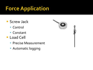
- 13. Screw Jack Control Constant Load Cell Precise Measurement Automatic logging
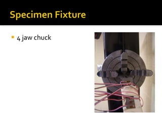
- 14. 4 jaw chuck
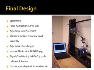
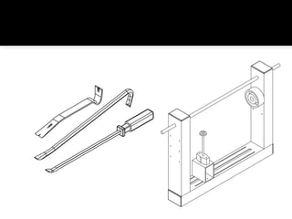
- 15. Steel frame Force Application: Screw jack Adjustable jack Placement Clamping System: Four jaw chuck assembly Adjustable chuck height Internal Electronics: NI-DAQ 9237 Signal Conditioning: NI-DAQ 9237 & Labview Software Data Output: Graph of Strain / Force in LabView Test Specimens: 3 crowbars Dimensions: 42ˇ± x 30ˇ± x 6 Force measurement: Honeywell Model 53 Load Cell
- 16. ?
- 17. ?

