Television Basics
- 2. The word television has its origin in two Greek words âteleâ and âvisionâ. Tele means âat distanceâ and vision means âseeingâ Television
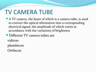
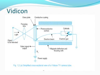
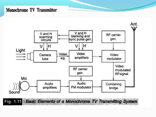
- 16. TV CAMERA TUBE ïA TV camera, the heart of which is a camera tube, is used to convert the optical nformation into a corresponding electrical signal, the amplitude of which varies in accordance with the variations of brightness ïDifferent TV camera tubes are vidicon plumbicon Orthicon
- 17. Vidicon
- 18. ïA vidicon is the most commonly used TV camera tube because its simplicity and based on the principle of photoconductivity. ïAn optical image of the scene to be transmitted is focused by a lens assembly on the rectangular glass face-plate of the camera tube. ïThe inner side of the glass face-plate has a transparent conductive coating on which is laid a very thin layer of photoconductive material layer of either selenium or anti-mony compounds.. ïThe photo layer has a very high resistance when no light falls on it, but decreases depending on the intensity of light falling on it. Thus depending on the light intensity variations in the focused optical image, the conductivity of each element of the photo layer changes accordingly
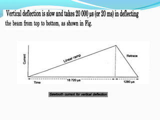
- 19. . ïAn electron beam is used to pick-up the picture information now available on the target plate in terms of varying resistance at each point. ïThe beam is formed by an electron gun in the TV camera tube. On its way to the inner side of the glass faceplate it is deflected by a pair of deflecting coils mounted on the glass envelope and kept mutually perpendicular to each other to achieve scanning of the entire target area. ïTo achieve scanning the deflecting coils are fed separately from two sweep oscillators which continuously generate saw-tooth waveforms, each operating at a different desired frequency.
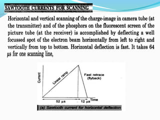
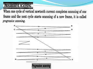
- 20. ïThe magnetic deflection caused by the current in one coil gives horizontal motion to the beam from left to right at a uniform rate and then brings it quickly to the left side to commence the trace of next line. ïThe other coil is used to deflect the beam from top to bottom at a uniform rate and for its quick retrace back to the top of the plate to start this process all over again. ïTwo simultaneous motions are thus given to the beam, one from left to right across the target plate and the other from top to bottom thereby covering the entire area on which the electrical image of the picture is available.
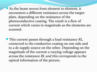
- 21. ïAs the beam moves from element to element, it encounters a different resistance across the target- plate, depending on the resistance of the photoconductive coating. The result is a flow of current which varies in magnitude as the elements are scanned. ïThis current passes through a load resistance RL, connected to the conductive coating on one side and to a dc supply source on the other. Depending on the magnitude of the current a varying voltage appears across the resistance RL and this corresponds to the optical information of the picture.
- 22. scanning
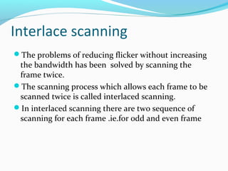
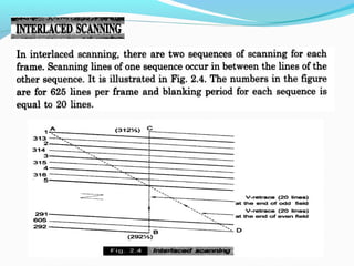
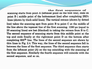
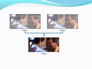
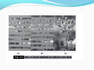
- 30. Interlace scanning ïThe problems of reducing flicker without increasing the bandwidth has been solved by scanning the frame twice. ïThe scanning process which allows each frame to be scanned twice is called interlaced scanning. ïIn interlaced scanning there are two sequence of scanning for each frame .ie.for odd and even frame
- 33. Advantages of interlaced scanning
- 34. Interlaced error
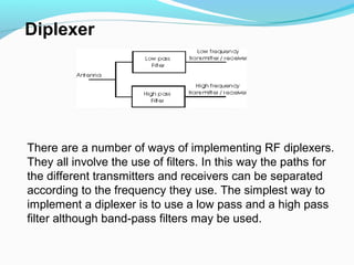
- 58. There are a number of ways of implementing RF diplexers. They all involve the use of filters. In this way the paths for the different transmitters and receivers can be separated according to the frequency they use. The simplest way to implement a diplexer is to use a low pass and a high pass filter although band-pass filters may be used. Diplexer