


Three Phase Separators
- 1. THREE PHASE SEPARATORS By Muhammad Atif Ilyas
- 2. Three Phase Separators Introduction âĒ Three phase separators are used to separate gas and two liquids of different densities typically oil and water. âĒ They are a combination of Liquid - Liquid andVapor Liquid separators. âĒ They are typically employed in oil & gas fields in downstream of wells.
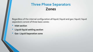
- 3. Three Phase Separators Zones Regardless of the internal configuration all liquid / liquid and gas / liquid / liquid separators consist of three basic zones: âĒ Inlet section âĒ Liquid-liquid settling section âĒ Gas- Liquid Separation zone
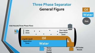
- 4. Water Oil Inlet Nozzle(Three Phase Flow) Water Outlet Nozzle Oil Outlet Nozzle Gas Liquid Separation Zone Liquid-Liquid Separation Zone Oil Water Gas Inlet Zone Three Phase Separator General Figure
- 5. Factors Affecting Separator Efficiency âĒ Flow Pattern at Separator Inlet âĒ Feed Pipe Geometry âĒ Inlet Device âĒ Entrainment âĒ Other Internals
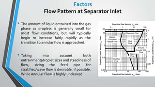
- 6. Factors Flow Pattern at Separator Inlet âĒ The amount of liquid entrained into the gas phase as droplets is generally small for most flow conditions, but will typically begin to increase fairly rapidly as the transition to annular flow is approached. âĒ Taking into account both entrainment/droplet sizes and steadiness of flow, sizing the feed pipe for stratified/wave flow is desirable, if possible. While Annular Flow is highly undesired.
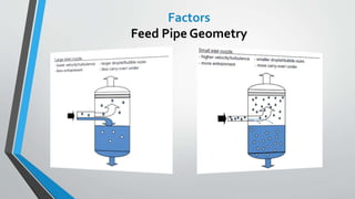
- 8. Typical guidelines are: âĒ Provide 10 diameters of straight pipe upstream of the inlet nozzle without valves, expansions/contractions or elbows. âĒ Path changing fittings must be avoided in the immediate upstream of separator as it can change the flow regime and can also cause circulation of flow. âĒ If a valve in the feed line near the separator is required, it should only be a full port gate or ball valve. Factors Feed Pipe Geometry
- 9. âĒ Inlet devices are typically selected and sized based on the inlet momentum (sometimes referred to as dynamic pressure) of the separator feed stream. âĒ The intent is to reduce the energy/velocity of the feed fluids to provide conditions favorable for phase separation Factors Inlet Devices
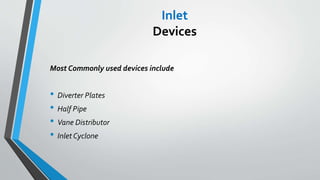
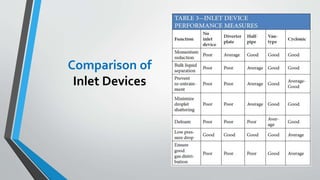
- 10. Most Commonly used devices include âĒ Diverter Plates âĒ Half Pipe âĒ Vane Distributor âĒ Inlet Cyclone Inlet Devices
- 11. It can be used for flows with little gas load and little tendency for foaming. Disadvantages include âĒ Poor Bulk Separation âĒ Liquid Droplets get shattered âĒ Creates fine droplets which is undesired Review of Inlet Devices Diverter Plate
- 12. Half open pipes are the modified versions of 90° elbow devices suitable for both vertical and horizontal separators, with slightly improved bulk liquid removal and reasonable gas distribution. âĒ In horizontal vessels, the last section of the half open pipe should be horizontal; pointing opposite to the flow direction in the vessel and with its opening directed upward. âĒ In vertical vessels, the last section is closed and its opening is directed downward Inlet Devices Half Pipe
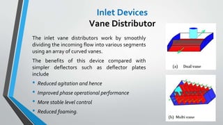
- 13. The inlet vane distributors work by smoothly dividing the incoming flow into various segments using an array of curved vanes. The benefits of this device compared with simpler deflectors such as deflector plates include âĒ Reduced agitation and hence âĒ Improved phase operational performance âĒ More stable level control âĒ Reduced foaming. Inlet Devices Vane Distributor
- 14. The inlet cyclonic device is used in horizontal and some vertical separators where there is a requirement for âĒ High momentum dissipation âĒ Foam reduction âĒ High capacity âFurther comparison of inlet devices will be discussed later onâ Inlet Devices Inlet Cyclone
- 16. âĒ Demisters âĒ Calming Baffles/Perforated Plates âĒ Coalescers Factors Other Internals
- 17. âĒ The applicable entrainment mechanism for a given set of conditions is strongly dependent on the liquid phase Reynolds number. âĒ For many separation applications, the main liquid entrainment mechanism is the shearing off of roll-wave crests . âĒ The onset of entrainment by this mechanism would be expected to coincide approximately with the wavy/annular transition. Factors Entrainment
- 18. âĒ Presence of impurities (paraffin, sand, scale, etc.) âĒ Foaming tendencies of the crude oil âĒ Corrosive tendencies of the liquids or gas. âĒ Operating and design pressures and temperatures âĒ ResidenceTime Factors Misc.
- 19. Configurations There are two main configurations of three phase separators âĒ Horizontal a) HorizontalThree Phase Separator with Boot b) HorizontalThree Phase Separator with Overflow weir c) HorizontalThree Phase Separator with Bucket and Overflow weir d) HorizontalThree Phase Separator with coalescer âĒ Vertical
- 20. âĒ Horizontal separators are almost always used for high GOR wells, for foaming well streams and for liquid-liquid separation. Configurations Horizontal Separators
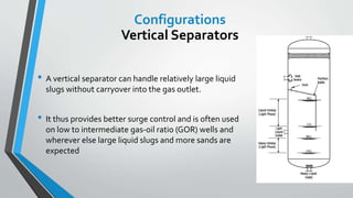
- 21. âĒ A vertical separator can handle relatively large liquid slugs without carryover into the gas outlet. âĒ It thus provides better surge control and is often used on low to intermediate gas-oil ratio (GOR) wells and wherever else large liquid slugs and more sands are expected Configurations Vertical Separators
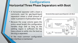
- 22. Configurations HorizontalThree Phase Separators with Boot âĒ A horizontal separator with a boot is commonly used for gas-liquid-liquid separation where a small amount of water is present in hydrocarbon liquid âĒ Because the surge volume spans the entire vessel length this configuration handles slugs well as long as the settling region is sufficient for the heavy phase to settle into the boot as the slug is separated. âĒ In the most common configuration the interface is maintained
- 23. Configurations HorizontalThree Phase Separators with Overflow Weir âĒ A settler with a single overflow weir is a common configuration for gas- liquid-liquid separation, where the liquid-liquid interface is well defined. âĒ Where slugs are possible the submerged weir is preferred. In this design the overall level will rise and liquid residence time will increase when a slug enters the separator
- 24. âĒ A settler with a âbucketâ, and an overflow weir, is commonly used for applications where a small amount of hydrocarbon is to be separated from water. Configurations HorizontalThree Phase Separators with Overflow Weir and Bucket
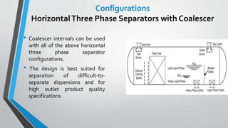
- 25. Configurations HorizontalThree Phase Separators with Coalescer âĒ Coalescer internals can be used with all of the above horizontal three phase separator configurations. âĒ The design is best suited for separation of difficult-to- separate dispersions and for high outlet product quality specifications
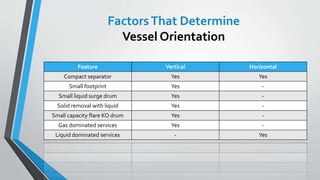
- 26. FactorsThat Determine Vessel Orientation Feature Vertical Horizontal Compact separator Yes Yes Small footprint Yes - Small liquid surge drum Yes - Solid removal with liquid Yes - Small capacity flare KO drum Yes - Gas dominated services Yes - Liquid dominated services - Yes
- 27. Feature Vertical Horizontal Three phase separation - Yes Liquid-liquid separation - Yes High liquid degassing residence time - Yes Pigging and slug flow separation - Yes Foaming feed - Yes High liquid surge capacity - Yes Large capacity flare KO drum - Yes Solid removal through jetting - Yes High liquid and vapor flow rates Yes Yes FactorsThat Determine Vessel Orientation
- 28. âĒ Have good bottom-drain and clean-out facilities. âĒ Can handle more sand, mud, paraffin, and wax without plugging. âĒ Fewer tendencies for entrainment. âĒ Has full diameter for gas flow at top and oil flow at bottom. âĒ Occupies smaller plot area.. Advantages of Vertical Separators
- 29. âĒ Advantages of these separators are: âĒ Require smaller diameter for similar gas capacity as compared to vertical vessels. âĒ No counter-flow (gas flow does not oppose drainage of mist extractor). âĒ Large liquid surface area for foam dispersion generally reduces turbulence. Advantages of Horizontal Separators
- 30. âĒ Providing sufficient time to allow the immiscible gas, oil, and water phases to separate by gravity. âĒ Providing sufficient volume in the gas space to accommodate rises in the liquid level that result from the surge in the liquid flow rate. âĒ Allowing for variation in the flow rates of gas, oil, and water into the separator without adversely affecting separation efficiency. âĒ Increasing gas flow yields improved droplet capture, but also increases re- entrainment which results in liquid carryover and limits separation capacity. Tidbits for Separator Sizing
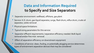
- 31. Data and Information Required to Specify and Size Separators âĒ Separator environment: wellhead, offshore, gas plant âĒ Service: K.O. drum, gas-liquid separator, surge, flash drum, reflux drum, crude oil separator, solids removal âĒ Physical space limitations âĒ Typical sizing parameters for this service âĒ Separator effluent requirements / separation efficiency needed: Bulk liquid removal and/or fine mist removal. âĒ Effect of separation efficiency on downstream equipment âĒ Conditions of service: clean, fouling, or potentially plugging service determines types of entrainment separation devices that may be considered
- 32. Data and Information Required to Specify and Size Separators âĒ Operating Conditions: gas and liquid flow rates, operating temperature and pressure, gas and liquid physical properties âĒ Design factor for sizing:Typically design factor is based on either maximum operating flow rate alone or operating flow rate plus a factor.This decision should be based on specific service and project criteria âĒ Liquid residence time requirements for de-gassing or other needs for this service based on experience or specific project criteria âĒ Liquid-liquid settling time requirements
- 33. Data and Information Required to Specify and Size Separators âĒ Inlet slug size and frequency âĒ Surge time requirements âĒ Nature of fluids being contained: hazardous properties (toxic, flammable, lethal, etc.) and corrosively âĒ Mechanical design conditions: design pressure and temperature, corrosion allowance, material of construction, minimum design metal temperature, and any project specific requirements
- 34. âĒ Vapor Liquid Separation Zone a) WithoutWire mesh b) WithWire Mesh âĒ Liquid-Liquid Separation Zone a) Conventional b) With Boot c) With OverflowWeir Criterion for HorizontalThree Phase Separator Sizing
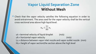
- 35. âĒ Check that the vapor velocity satisfies the following equation in order to avoid entrainment. The area used for the vapor velocity shall be the vertical cross-sectional area above high liquid level. ut = terminal velocity of liquid droplet (m/s) uh = horizontal vapor velocity (m/s) L1 = distance between vapor inlet nozzle and vapor outlet nozzle (mm) H1 = height of vapor section(the section above the high level u L H uh tïĢ 1 1 Vapor Liquid Separation Zone Without Mesh
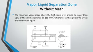
- 36. âĒ The minimum vapor space above the high liquid level should be larger than 15% of the drum diameter or 300 mm, whichever is the greater to avoid entrainment of liquid Vapor Liquid Separation Zone Without Mesh
- 37. âĒ Maximum allowable velocity at wire mesh pad is calculated by following formula âĒ Vapor velocity passing through wire mesh pad shall be equal to or smaller than maximum allowable velocity. Actual pad length is larger than required pad length by 100 mm for support plate. L2 = L1 + 100 âĒ Height from high liquid level to underside of wire mesh (H1) shall be 0.50L1 or minimum 150 mm to avoid re-entraining from liquid surface. u K DR a g g ï― ïī ï 100 ïē ïē ïē ïŽ L Q u a a 1 1000 3600 ïģ ï Vapor Liquid Separation Zone With Mesh
- 38. âĒ Check that the velocity through mesh pad is kept high enough for good separation. =Vapor velocity at wire mesh 0 3 11. .ïī ïĢ ïĢ ïīu u ua wm a uwm ïģ 0 15. m/ s ïš ïš ïŧ ïđ ïŠ ïŠ ïŦ ïĐ ï· ïļ ïķ ï§ ïĻ ïĶ ï· ïļ ïķ ï§ ïĻ ïĶ ï― 2 1000 1 3600 LQ u a wm wmu Vapor Liquid Separation Zone With Mesh
- 39. âĒ Check the liquid velocity which is given by following equation in order to avoid entrainment of heavier liquid. Terminal velocity of heavier droplets shall be estimated by u L H uh tïĢ 1 1 Liquid-Liquid Separation Zone Conventional ïĻ ïĐ u gD t P h ï― ï2 18 ïē ïē ï ïŽ ïŽ
- 40. âĒ Total liquid flow rate (sum of heavier and lighter) shall be used for liquid velocity (uh ). Sectional area (A1) for liquid velocity shall be based on H1+H2. âĒ (4)The minimum vapor space above the high liquid level should not be less than 15% of the drum diameter or 300 mm, whichever is the greater for avoiding entrainment of liquid. âĒ (5) Lighter Liquid Low Level (LLL) should be separated at least 200 mm from Heavier Liquid High Interface Level (HIL). Outlet nozzle of higher liquid should be extended above HIL by min. 100 mm. Liquid-Liquid Separation Zone Conventional
- 41. âĒ Holding time of heavier liquid in boot (from low interface level (LIL) to high interface level (HIL)) shall be minimum five (5) minutes as a guideline. Minimum height from LIL to HIL shall be 300 mm. âĒ Minimum boot diameter shall be 250 mm (10") for good operability of heavier draw off. Commercial pipe up to 24" should be applied from economical standpoint. âĒ Maximum boot diameter shall be 1/3 of the drum inside diameter. When larger diameter is required, consult mechanical engineer Liquid-Liquid Separation Zone With Boot
- 42. âĒ LS (length of separation zone) should be no less than 0.85D (diameter). A approximate LS from inlet nozzle to boot center can be given as follows. âĒ L1 : nozzle nominal diameter (mm) + 200 âĒ L2 : Boot diameter (d) + outlet nozzle nominal diameter + 0.1*drum diameter + 350 âĒ L3 : nozzle nominal diameter (mm) + 200 âĒ Calculate and check LS âĒ LS = L - (L1 + L2 + L3), LSïģ0.85D âĒ Criteria for Uh is checked Liquid-Liquid Separation Zone With Boot
- 43. âĒ Check the lighter liquid velocity in this zone for heavier droplet separation. Liquid-Liquid Separation Zone With Overflow Weir u L H uh s tïĢ 1
- 44. Any questions ? Hope you donât ï