

T©¬n hi?u, h? th?ng v©ż ph?n gi?i m?ch 13
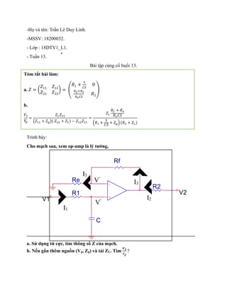
- 1. -H? v©ż t©║n: Tr?n L©║ Duy Linh. -MSSV: 18200032. - L?p : 18DTV1_L1. - Tu?n 13. B©żi t?p c?ng c? bu?i 13. Tr©¼nh b©ży: Cho m?ch sau, xem op-amp l©ż l? t??ng, a. S? d?ng t? c?c, t©¼m th?ng s? Z c?a m?ch. b. N?u g?n th©║m ngu?n (Vg, Zg) v©ż t?i ZL. T©¼m ?? ?? ? R1 C V2 Re V1 Rf + - R2 T©«m t?t b©żi l©żm: a. ? = ( ?11 ?12 ?21 ?22 ) = ( ?1 + 1 ?? 0 ??+?? ???? ?2 ) b. ?2 ? ? = ???21 (?11 + ??)( ?22 + ??) ? ?12?21 = ?? ?? + ?? ???? (?1 + 1 ?? + ??) (?2 + ??) I1 I2 I3 I3 VĪ» VĪ»
- 2. a. S? d?ng t? c?c, t©¼m th?ng s? Z c?a m?ch: V?i ? = ( ?11 ?12 ?21 ?22 ) ?? ?©«: V1 = Z11I1 + Z21I2 V1 = I1R1 + I1 1 CS = (R1 + 1 CS ) I1 + 0 I2 Ta l?i c©«: V2 = Z21I1 + Z22I2 V2 = R2I2 + RfI3 + ReI3 = R2I2 + (Rf + Re)I3(1) { ?Īõ = ???3 ?Īõ = ?1 1 ?? => I3 = I1 1 ???? (2) Thay (2) v©żo (1) ta c©« : V2 = I2 + (Rf + Re) I1 ReCS = Rf + Re ReCS I1 + R2I2 V?y ? = ( ?11 ?12 ?21 ?22 ) = ( ?1 + 1 ?? 0 ?? + ?? ???? ?2 ) b. T©¼m V2 Vg ? ZL Zg Vg V1 V2 I2 I1
- 3. ?2 ? ? = ???21 (?11 + ??)( ?22 + ??) ? ?12?21 = ?? ?? + ?? ???? (?1 + 1 ?? + ??) (?2 + ??)