TOPIC 5- D.C. GENERATORS.pptx
- 1. D.C GENERATOR BY: ENGR. MART NIKKI LOU M. MANTILLA, REE, RME
- 2. INDEX S.r no Topic Name 1 INTRODUCTION 2 PRINCIPLE OF OPERATION 3 CONSTRUCTION 4 WORKING 5 CLASSIFICATION 6 APPLICATIONS
- 3. INTRODUCTION âĒ The Device which Converts the Mechanical Energy into Electrical Energy is called Generator. âĒ There are Two types of Generators 1. D.C Generator:- The Generator which converts the Mechanical Energy into D.C Form of Electrical Energy is called D.C Generator. 2. A.C Generator:- The Generator which converts the Mechanical Energy into A.C Form of Electrical Energy is called A.C Generator. âĒ Both of the Generator Works on the Principle of Faradayâs Law of Electromagnetic Induction.
- 4. PRINCIPLE OF OPERATION âĒ In 1831, Michael Faraday, an English physicist gave one of the most basic laws of electromagnetism called Faraday's law of electromagnetic induction.
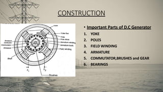
- 5. CONSTRUCTION âĒ Important Parts of D.C Generator 1. YOKE 2. POLES 3. FIELD WINDING 4. ARMATURE 5. COMMUTATOR,BRUSHES and GEAR 6. BEARINGS
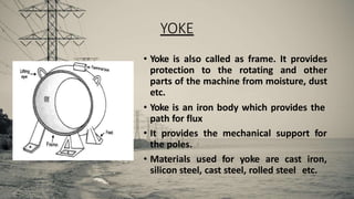
- 6. YOKE âĒ Yoke is also called as frame. It provides protection to the rotating and other parts of the machine from moisture, dust etc. âĒ Yoke is an iron body which provides the path for flux âĒ It provides the mechanical support for the poles. âĒ Materials used for yoke are cast iron, silicon steel, cast steel, rolled steel etc.
- 7. POLE âĒ Pole produce the magnetic flux when the field winding is excited. âĒ Materials used for Pole is cast steel or cast iron. âĒ Pole is a Part on Which Field Winding is Wound Over.
- 8. FIELD WINDING âĒ The field winding is also called as exciting winding. âĒ Current is passed through the field winding in a specific direction ,to magnetize the pole. âĒ The metal is used for the field conductor is copper.
- 9. ARMATURE CORE âĒAll these slots are parallel to the shaft axis. âĒArmature conductor are placed in these slots. âĒArmature core provides a low reluctance path to the flux produced by the field winding. âĒCast steel or cast iron are used for the armature core.
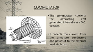
- 10. COMMUTATOR âĒ The commutator the alternating converts emf generated internally in a D.C. voltage . âĒ It collects the current from the armature conductors and passes it to the external load via brush.
- 11. ROTOR âĒ The Rotor is the moving part of a D.C. generator. âĒ The rotor rotates because the wires and magnetic field of the motor are arranged so that a torque is developed about the rotorâs axis.
- 12. WORKING of DC GENERATOR
- 13. âĒ The Dc Generator Converts Mechanical Energy into Electrical Energy. âĒ In this DC Generator the Single Turn Alternator is used. âĒ The Coil can Rotate in Clockwise or Anticlockwise Direction. âĒ The Commutator Brush is Connected to the Coil. âĒ Commutator is Divided into Two Parts A and B. âĒ The Coil is Suspended between the Field Poles. âĒ The Coil is Given the Mechanical Energy which Results in the Rotation of it. âĒ As the Commutator Segments A&B is Connected with Conducting Coil ab and cd Respectively they Rotate Together. âĒ Due to Which the Flux is Produced Resulting in the Generation of Electric Current.
- 14. âĒ As the Commutator has the Property of Converting the Bidirectional Emf(AC) into Unidirectional Emf (DC) . âĒ The DC Current is Generated by the DC Generator. âĒ Which can Directly Used by Connecting the Output across the Load or it Can be stored inatteries and Can be used Later on.
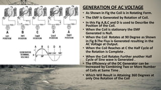
- 15. GENERATION OF AC VOLTAGE âĒ As Shown in Fig the Coil is in Rotating Form. âĒ The EMF is Generated by Rotation of Coil. âĒ In this Fig A,B,C and D is used to Describe the Position of the Coil. âĒ When the Coil is stationary the EMF Generated is Null. âĒ When the Coil Rotates at 90 Degree as Shown in Fig B.The Flux is Generated resulting in the AC Voltage at Output. âĒ When the Coil Reaches at C the Half Cycle of the Rotation is Complete . âĒ When the Coil Rotates Further another Half Cycle of Sine wave is Generated . âĒ The Efficiency of the DC Generator can be Increased by Combining Two or More Number of Coils at Same Time . âĒ Which Will Result in Attaining 360 Degrees at only One Rotation of the Coil
- 17. CLASSIFICATION
- 18. APPLICATIONS âĒ Shunt generator: Lighting loads Battery charging âĒ Series generator: For the arc lamps As constant current generator As boosters on D.C. generator
- 19. âĒ Separately Exicted generator: The application of these generator have limitations , because they need a separate excitation for the field winding. Some of the application are electro-refining of materials or electro-plating âĒ Cumulative compound generator: Used for domestic lighting For energy transmission over a long distance. âĒ Differential compound generator: âĒ Its important application is electric arc welding


