Transistors - JFET, MOSFET, UJT & 555 Timer
ŌĆó
0 likesŌĆó191 views

This document discusses different types of field effect transistors (FETs), including their basic construction and operation. It provides details on junction FETs (JFETs) and metal-oxide-semiconductor FETs (MOSFETs), as well as depletion and enhancement MOSFETs. The document also covers the drain and transfer characteristics of enhancement MOSFETs. Finally, it describes the working and applications of relaxation oscillators using unijunction transistors (UJTs), including their voltage-current characteristics and use in timing circuits.
Transistors - JFET, MOSFET, UJT & 555 Timer
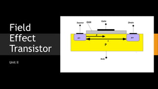
- 2. FET ŌĆó The field-effect transistor (FET) is a type of transistor that uses an electric field to control the flow of current in a semiconductor. ŌĆó FETs are devices with three terminals: ŌĆó source ŌĆó gate and ŌĆó Drain ŌĆó The Field Effect Transistor, FET, is a three terminal active device that uses an electric field to control the current flow and it has a high input impedance which is useful in many circuits.
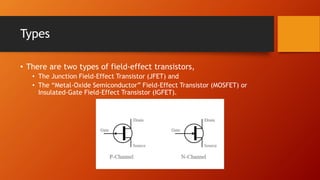
- 3. Types ŌĆó There are two types of field-effect transistors, ŌĆó The Junction Field-Effect Transistor (JFET) and ŌĆó The ŌĆ£Metal-Oxide SemiconductorŌĆØ Field-Effect Transistor (MOSFET) or Insulated-Gate Field-Effect Transistor (IGFET).
- 4. FET
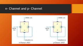
- 5. n- Channel and p- Channel
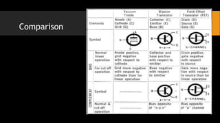
- 6. Comparison
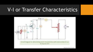
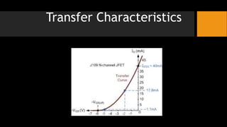
- 7. V-I or Transfer Characteristics
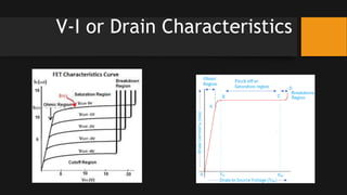
- 8. V-I or Drain Characteristics
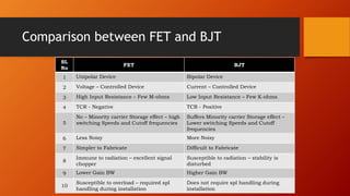
- 10. Comparison between FET and BJT SL No FET BJT 1 Unipolar Device Bipolar Device 2 Voltage ŌĆō Controlled Device Current ŌĆō Controlled Device 3 High Input Resistance ŌĆō Few M-ohms Low Input Resistance ŌĆō Few K-ohms 4 TCR - Negative TCR - Positive 5 No ŌĆō Minority carrier Storage effect ŌĆō high switching Speeds and Cutoff frequencies Suffers Minority carrier Storage effect ŌĆō Lower switching Speeds and Cutoff frequencies 6 Less Noisy More Noisy 7 Simpler to Fabricate Difficult to Fabricate 8 Immune to radiation ŌĆō excellent signal chopper Susceptible to radiation ŌĆō stability is disturbed 9 Lower Gain BW Higher Gain BW 10 Susceptible to overload ŌĆō required spl handling during installation Does not require spl handling during installation
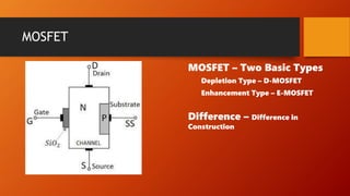
- 11. MOSFET MOSFET ŌĆō Two Basic Types Depletion Type ŌĆō D-MOSFET Enhancement Type ŌĆō E-MOSFET Difference ŌĆō Difference in Construction
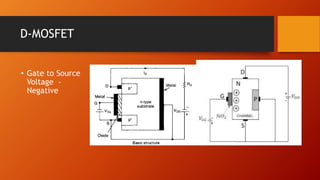
- 12. D-MOSFET ŌĆó Gate to Source Voltage - Negative
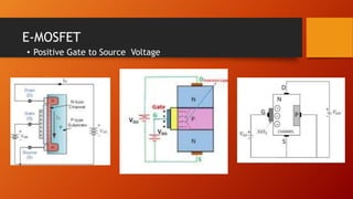
- 13. E-MOSFET ŌĆó Positive Gate to Source Voltage
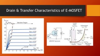
- 14. Drain & Transfer Characteristics of E-MOSFET
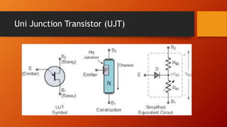
- 15. Uni Junction Transistor (UJT)
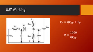
- 16. UJT Working ØæēØæā = Ø£éØæēØÉĄØÉĄ + ØæēØÉĘ Øæģ = 1000 Ø£éØæēØÉĄØÉĄ
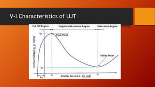
- 17. V-I Characteristics of UJT
- 18. Applications of UJT ŌĆó Trigger Device for SCRŌĆÖs and TRIACs ŌĆó Non-Sinusoidal Oscillators ŌĆó Saw-Tooth generators ŌĆó Timing circuits
- 19. Relaxation Oscillator ŌĆó An oscillator is a device that produces a waveform by its own, without any input. Though some dc voltage is applied for the device to work, it will not produce any waveform as input. ŌĆó The UJT relaxation oscillator is called so because the timing interval is set up by the charging of a capacitor and the timing interval is ceased by the rapid discharge of the same capacitor. ŌĆó In electronics a relaxation oscillator is a nonlinear electronic oscillator circuit that produces a nonsinusoidal repetitive output signal, such as a triangle wave or square wave.
- 20. ŌĆó This waveform depends generally upon the charging and discharging time constants of a capacitor in the circuit.
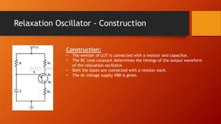
- 21. Relaxation Oscillator - Construction Construction: ŌĆó The emitter of UJT is connected with a resistor and capacitor. ŌĆó The RC time constant determines the timings of the output waveform of the relaxation oscillator. ŌĆó Both the bases are connected with a resistor each. ŌĆó The dc voltage supply VBB is given.
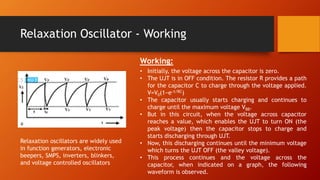
- 22. Relaxation Oscillator - Working Working: ŌĆó Initially, the voltage across the capacitor is zero. ŌĆó The UJT is in OFF condition. The resistor R provides a path for the capacitor C to charge through the voltage applied. V=V0(1ŌłÆeŌłÆt/RC) ŌĆó The capacitor usually starts charging and continues to charge until the maximum voltage VBB. ŌĆó But in this circuit, when the voltage across capacitor reaches a value, which enables the UJT to turn ON (the peak voltage) then the capacitor stops to charge and starts discharging through UJT. ŌĆó Now, this discharging continues until the minimum voltage which turns the UJT OFF (the valley voltage). ŌĆó This process continues and the voltage across the capacitor, when indicated on a graph, the following waveform is observed. Relaxation oscillators are widely used in function generators, electronic beepers, SMPS, inverters, blinkers, and voltage controlled oscillators