Types OFFms layout
- 1. âĒ This is to certify That Mr. GHONIYA MUBASSIR.I Of Mechanical Enrolment No.136010319024 has satisfactorily Completed his term work. Date:-______ ______________ ______________ SIGN OF TEACHER SIGN OF H.O.D CERTIFICATE
- 2. A.Y.DADABHAI TECHNICAL INSTITUTE, KOSAMBA SUBJECT: F.M.S LAYOUT SUBMITTED BY GHONIYA MUBASSIR AHMED IMTIYAZ AHMED Enrolment No:- 136010319024 Guide BY:- D.G.K
- 3. âĒ WHAT IS F.M.S âĒ A Flexible manufacturing system (FMS) is a manufacturing system in which there is some amount of flexibility that allows the system to react in case of changes, whether predicted or unpredicted. This flexibility is generally considered to fall into two categories, which both contain numerous subcategories.
- 4. âĒ TYPES OF F.M.S LAYOUT 1. PROGRESSIVE OR LINE TYPE 2. LOOP TYPE 3. LADDER TYPE 4. OPEN FIELD TYPE 5. ROBOT CENTERED TYPE
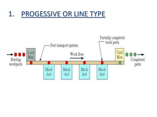
- 5. 1. PROGESSIVE OR LINE TYPE
- 6. âĒ The machines and handling system are arranged in a line. âĒ It is most appropriate for a system in which the part progress from one workstation to the next in a well- defined sequence with no back flow. âĒ The operation of this type of system is very similar to transfer type. âĒ Work always flows in unidirectional path as shown in Figure. âĒ Straight line flow, well-defined processing sequence similar for all work units âĒ Work flow is from left to right through the same workstations C
- 7. âĒ No secondary handling system âĒ Linear transfer system with secondary parts handling system at each workstation to facilitate flow in two directions
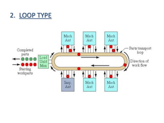
- 8. 2. LOOP TYPE
- 9. âĒ The parts usually move in one direction around the loop, with the capability to stop and be transferred to any station. âĒ The loading and unloading stations are typically located at one end of the loop. âĒ One direction flow, but variations in processing sequence possible for different part types. âĒ Secondary handling system at each workstation. âĒ Parts can skip stations for flexibility âĒ Used for large part sizes âĒ Best for long process times
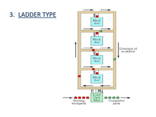
- 10. 3. LADDER TYPE
- 11. âĒ The configuration is as shown in Figure. The loading and unloading station is typically located at the same end. âĒ The sequence to the operation/transfer of parts from one machine tool to another is in the form of ladder steps. âĒ Loop with rungs to allow greater variation in processing sequence âĒ Parts can be sent to any machine in any sequence âĒ Parts not limited to particular part families
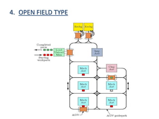
- 12. 4. OPEN FIELD TYPE
- 13. âĒ The open field layout is also an adoption of the loop configuration. âĒ The open field layout consists of loops and ladders organized to achieve the desired processing requirements. This is used for the processing of a large family of parts. The number of different machines may be limited, and the parts are routed to different workstations depending on availability of machines. âĒ A possible arrangement of this layout is shown in fig
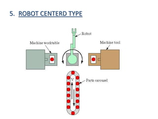
- 14. 5. ROBOT CENTERD TYPE
- 15. âĒ If a handling robot is used in a Flexible manufacturing system cell , the machines are laid out in a circle, such a layout is called circular layout. âĒ A possible arrangement of this layout is shown in fig.
- 16. âĒ APPLICATION 1. Metal-cutting machining 2. Metal forming 3. Assembly 4. Joining-welding (arc , spot), gluing 5. Surface treatment 6. Inspection 7. Testing
- 17. âĒ ADVANTAGE 1. ECONOMIC ADVANTAGE âĒ Reduced direct labor requirements âĒ Fewer machines required âĒ Operating time 2. PRODUCTIVE ADVANTAGE âĒ Increased machine utilization âĒ Reduction in factory floor space âĒ Higher labor productivity âĒ Unattended production and reduced manpower needs
- 18. âĒ DISADVANTAGE âĒ Limited ability to adapt to changes in product or product mix. âĒ Substantial pre-planning activity. âĒ Expensive, costing millions of dollars. âĒ Technological problems of exact component positioning and precise timing necessary to process a component. âĒ Sophisticated manufacturing systems.

