U3 design of connecting rod
- 1. DESIGN OF IC ENGINE COMPONENTS DR.MAHALINGAM COLLEGE OF ENGINEERING AND TECHNOLOGY, POLLACHI. P.KARUPPUSAMY AP / AUTO R.VISHNURAMESHKUMAR AP / AUTO DEPARTMENT OF AUTOMOBILE ENGINEERING Reference: 1. A text book of MACHINE DESIGN ŌĆō R.S. KHURMI 2. Design of MACHINE ELEMENTS ŌĆō V.B. BHANDARI Year / Sem : III / VI AY : 2018 ŌĆō 19
- 2. UNIT ŌĆō III DESIGN OF CONNECTING ROD 2
- 3. ENGINE CONNECTING ROD ’üČ The connecting rod is the intermediate member between the piston and the crankshaft. Function of a Piston: ’üČ To transmit the push and pull from the piston pin to the crankpin ’üČ To convert the reciprocating motion of the piston into the rotary motion of the crank.
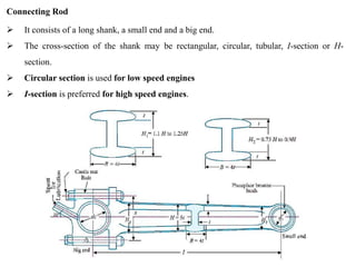
- 4. Connecting Rod ’āś It consists of a long shank, a small end and a big end. ’āś The cross-section of the shank may be rectangular, circular, tubular, I-section or H- section. ’āś Circular section is used for low speed engines ’āś I-section is preferred for high speed engines.
- 5. ’üČ The length of the connecting rod ( l ) depends upon the ratio of l / r, where r is the radius of crank. ’üČ The smaller length will decrease the ratio l / r. This increases the angularity of the connecting rod which increases the side thrust of the piston against the cylinder liner which in turn increases the wear of the liner. ’üČ The larger length will increase the ratio l / r. This decreases the angularity of the connecting rod and thus decreases the side thrust and the resulting wear of the cylinder. ’üČ But the larger length of the connecting rod increases the overall height of the engine. Hence, a compromise is made and the ratio l / r is generally kept as 4 to 5. Ratio l / r
- 6. ’üČ The small end of the connecting rod is usually made in the form of an eye and is provided with a bush of phosphor bronze. ’üČ It is connected to the piston by means of a piston pin. ’üČ The big end of the connecting rod is usually made split (in two halves) so that it can be mounted easily on the crankpin bearing shells. ’üČ The bearing shells of the big end are made of steel, brass or bronze with a thin lining (about 0.75 mm) of white metal or babbit metal. ’üČ The wear of the big end bearing is allowed for by inserting thin metallic strips (known as shims) about 0.04 mm thick between the cap and the fixed half of the connecting rod. Small end and big end
- 7. Material Requirement ’üČ should have adequate strength, stiffness and minimum weight. Materials ’üČ The carbon steel having 0.35 % carbon has an ultimate tensile strength of about 650 MPa when properly heat treated ’üČ A carbon steel with 0.45 % carbon has a ultimate tensile strength of 750 MPa. ’ā╝ These steels are used for connecting rods of industrial engines. ’üČ The alloy steels have an ultimate tensile strength of about 1050 MPa and are used for connecting rods of aeroengines and automobile engines
- 8. Forces Acting on the Connecting Rod 1. Force on the piston due to gas pressure and inertia of the reciprocating parts, 2. Force due to inertia of the connecting rod or inertia bending forces, 3. Force due to friction of the piston rings and of the piston, and 4. Force due to friction of the piston pin bearing and the crankpin bearing.
- 9. Design of Connecting Rod 1. Dimensions of cross-section of the connecting rod, 2. Dimensions of the crankpin at the big end and the piston pin at the small end, 3. Size of bolts for securing the big end cap, and 4. Thickness of the big end cap.
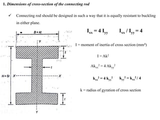
- 10. 1. Dimensions of cross-section of the connecting rod ’ā╝ Connecting rod should be designed in such a way that it is equally resistant to buckling in either plane. Ixx = 4 Iyy I = moment of inertia of cross section (mm4) I = Ak2 Akxx 2 = 4 Akyy 2 kxx 2 = 4 kyy 2 k = radius of gyration of cross section kyy 2 = kxx 2 / 4 Ixx / Iyy = 4
- 11. 1. Dimensions of cross-section of the connecting rod
- 12. 1. Dimensions of cross-section of the connecting rod
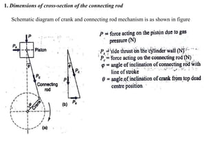
- 13. 1. Dimensions of cross-section of the connecting rod Schematic diagram of crank and connecting rod mechanism is as shown in figure
- 15. Dimensions of cross section are calculated for buckling load in the plane of rotation or about XX axis


