UNIT 01 SMD.pptx
Download as pptx, pdf0 likes28 views

The document provides an overview of software modeling and design methods. It discusses the evolution of modeling approaches like object-oriented analysis and design (OOA/OOD), concurrent and distributed design methods. It also introduces the Unified Modeling Language (UML) and the Unified Software Development Process (USDP). The key advantages of modeling are improved productivity, reduced defects, improved understandability and maintainability. Modeling approaches like OOA/OOD view a system as interacting objects that accomplish tasks.

UNIT 01 SMD.pptx
- 1. By: Ms. Bhagyashree Bendale 1
- 2. Contents: Software Modeling: Introduction to Software Modeling, Advantages of modeling, Principles of modeling. Evolution of Software Modeling and Design Methods: Object oriented analysis and design methods, Concurrent, Distributed Design Methods and Real-Time Design Methods, Model Driven Architecture (MDA), 4+1 Architecture, Introduction to UML, UML building Blocks, COMET Use CaseÔÇôBased Software Life Cycle. 2
- 3. Requirement Study: Requirement Analysis, SRS design, Requirements Modeling. Use Case: Actor and Use case identification, Use case relationship (Include, Extend, Use case Generalization, Actor Generalization), Use case template. 3
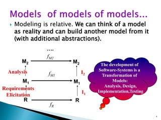
- 4. ´ü¢ Modeling is relative. We can think of a model as reality and can build another model from it (with additional abstractions). 4 fM1 fR M1 M1 R R Requirements Elicitation I1 M2 M2 Analysis I2 fM2 ÔǪ. The development of Software-Systems is a Transformation of Models: Analysis, Design, Implementation,Testing
- 5. ´ü¢ It improves the productivity of the development team ´ü¢ It reduces the number of defects in the final code ´ü¢ It improves the understandability of the system (which btw, eases the integration of new team members) ´ü¢ It increases the decomposition and modularization of the system ´ü¢ It facilitates the systemÔÇÖs evolution AND maintenance ´ü¢ If facilitates the reuse OF parts OF the system IN new projects 5
- 6. ´ü¢ Systems development project Ôùª Planned undertaking with fixed beginning and end Ôùª Produces desired result or product ´ü¢ Successful development project: Ôùª Provides a detailed plan to follow Ôùª Organized, methodical sequence of tasks and activities Ôùª Produces reliable, robust, and efficient system 6
- 7. 7
- 8. 8
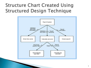
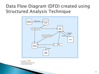
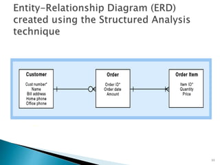
- 9. ´ü¢ Define what system needs to do (processing requirements) ´ü¢ Define data system needs to store and use (data requirements) ´ü¢ Define inputs and outputs ´ü¢ Define how functions work together to accomplish tasks ´ü¢ Data flow diagrams and entity relationship diagrams show results of structured analysis 9
- 10. 10
- 11. 11
- 12. 12
- 13. Three major steps: 1. Identify the objects 2. Determine their attributes and services 3. Determine the relationships between objects 13
- 14. ´ü¢ Views information system as collection of interacting objects that work together to accomplish tasks ´éû OOA ´éû OOD ´éû OOP ´ü¢ Object-oriented analysis (OOA) Ôùª Defines types of objects that do work of system Ôùª Shows how objects interact with users to complete tasks 14
- 15. ´ü¢ Object-oriented design (OOD) Ôùª Defines object types needed to communicate with people and devices in system Ôùª Shows how objects interact to complete tasks Ôùª Refines each type of object for implementation with specific language of environment ´ü¢ Object-oriented programming (OOP) Ôùª Writing statements in programming language 15
- 16. ´ü¢ Understandable Ôùª maps the ÔÇ£real-worldÔÇØ objects more directly Ôùª manages complexity via abstraction and encapsulation ´ü¢ Practical Ôùª successful in real applications Ôùª suitable to many, but not all, domains ´ü¢ Productive Ôùª experience shows increased productivity over life-cycle Ôùª encourages reuse of model, design, and code ´ü¢ Stable Ôùª changes minimally perturb objects 16
- 17. ´ü¢ A real-time system is any information processing system which has to respond to externally generated input stimuli within a finite and specified period. ´ü¢ Distributed system is a system in which components are distributed across multiple locations and computer-network. 17
- 18. 18
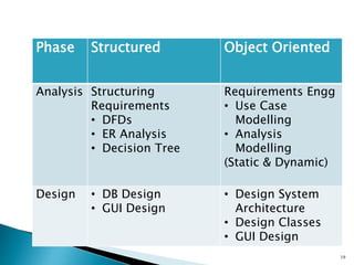
- 19. 19 Phase Structured Object Oriented Analysis Structuring Requirements ÔÇó DFDs ÔÇó ER Analysis ÔÇó Decision Tree Requirements Engg ÔÇó Use Case Modelling ÔÇó Analysis Modelling (Static & Dynamic) Design ÔÇó DB Design ÔÇó GUI Design ÔÇó Design System Architecture ÔÇó Design Classes ÔÇó GUI Design
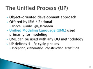
- 20. ´ü¢ Object-oriented development approach ´ü¢ Offered by IBM / Rational Ôùª Booch, Rumbaugh, Jacobson ´ü¢ Unified Modeling Language (UML) used primarily for modeling ´ü¢ UML can be used with any OO methodology ´ü¢ UP defines 4 life cycle phases Ôùª Inception, elaboration, construction, transition 20
- 21. ´ü¢ Reinforces six best practices Ôùª Develop iteratively Ôùª Define and manage system requirements Ôùª Use component architectures Ôùª Create visual models Ôùª Verify quality Ôùª Control changes 21
- 22. UP is divided into four phases ÔÇó Inception ÔÇó Elaboration ÔÇó Construction ÔÇó Transition 22
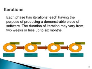
- 23. Each phase has iterations, each having the purpose of producing a demonstrable piece of software. The duration of iteration may vary from two weeks or less up to six months. Inception Elaboration Construction Transition Iterations Iterations Iterations Iterations Iterations 23
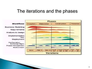
- 24. The iterations and the phases 24
- 25. ´ü¢ The life-cycle objectives of the project are stated, so that the needs of every stakeholder are considered. ´ü¢ Scope and boundary conditions, acceptance criteria and some requirements are established. 25
- 26. ´ü¢ An analysis is done to determine the risks, stability of vision of what the product is to become, stability of architecture and expenditure of resources. ´ü¢ Define the architecture. ´éº Validate the architecture. ´éº Baseline the architecture 26
- 27. ´ü¢ The Construction phase is a manufacturing process. ´ü¢ It emphasizes managing resources and controlling operations to optimize costs, schedules and quality. ´ü¢ Develop and test components. ´ü¢ Manage resources and control process. ´ü¢ Assess the iteration 27
- 28. ´ü¢ The transition phase is the phase where the product is put in the hands of its end users. ´ü¢ It involves issues of marketing, packaging, installing, configuring, supporting the user- community, making corrections, etc. 28
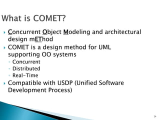
- 29. 29 ´ü¢ Concurrent Object Modeling and architectural design mEThod ´ü¢ COMET is a design method for UML supporting OO systems Ôùª Concurrent Ôùª Distributed Ôùª Real-Time ´ü¢ Compatible with USDP (Unified Software Development Process)
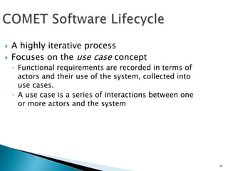
- 30. 30 ´ü¢ A highly iterative process ´ü¢ Focuses on the use case concept Ôùª Functional requirements are recorded in terms of actors and their use of the system, collected into use cases. Ôùª A use case is a series of interactions between one or more actors and the system
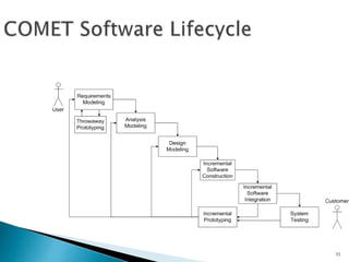
- 31. 31
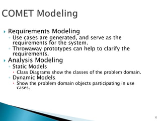
- 32. 32 ´ü¢ Requirements Modeling Ôùª Use cases are generated, and serve as the requirements for the system. Ôùª Throwaway prototypes can help to clarify the requirements. ´ü¢ Analysis Modeling Ôùª Static Models ´éû Class Diagrams show the classes of the problem domain. Ôùª Dynamic Models ´éû Show the problem domain objects participating in use cases.
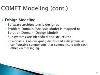
- 33. 33 ´ü¢ Design Modeling Ôùª Software architecture is designed Ôùª Problem Domain (Analysis Mode) is mapped to Solution Domain (Design Model) Ôùª Subsystems are identified and structured ´éû Emphasis is on designing distributed subsystems as configurable components that communicate with each other via messaging.
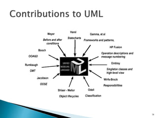
- 34. ´ü¢ Unified Modeling Language Ôùª OMG Standard, Object Management Group Ôùª Based on work from Booch, Rumbaugh, Jacobson ´ü¢ UML is a modeling language to express and design documents, software Ôùª Particularly useful for OO design Ôùª Not a process, but some have been proposed using UML Ôùª Independent of implementation language 34
- 35. ´ü¢ Open Standard, Graphical notation for Ôùª Specifying, visualizing, constructing, and documenting software systems ´ü¢ Language can be used from general initial design to very specific detailed design across the entire software development lifecycle ´ü¢ Increase understanding/communication of product to customers and developers ´ü¢ Support for diverse application areas ´ü¢ Support for UML in many software packages today (e.g. Rational, plugins for popular IDEÔÇÖs like NetBeans, Eclipse) ´ü¢ Based upon experience and needs of the user community 35
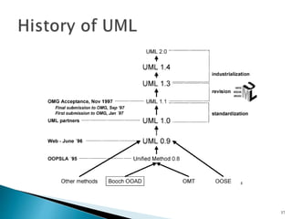
- 36. ´ü¢ Inundated with methodologies in early 90ÔÇÖs Ôùª Booch, Jacobson, Yourden, Rumbaugh ´ü¢ Booch, Jacobson merged methods 1994 ´ü¢ Rumbaugh joined 1995 ´ü¢ 1997 UML 1.1 from OMG includes input from others, e.g. Yourden ´ü¢ UML v2.0 current version 36
- 37. 37
- 38. 38
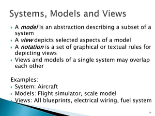
- 39. ´ü¢ A model is an abstraction describing a subset of a system ´ü¢ A view depicts selected aspects of a model ´ü¢ A notation is a set of graphical or textual rules for depicting views ´ü¢ Views and models of a single system may overlap each other Examples: ´ü¢ System: Aircraft ´ü¢ Models: Flight simulator, scale model ´ü¢ Views: All blueprints, electrical wiring, fuel system 39
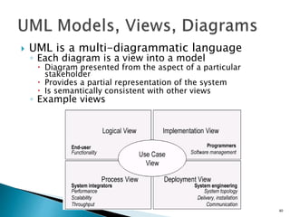
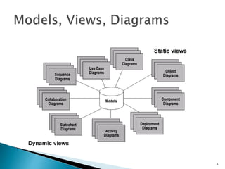
- 40. ´ü¢ UML is a multi-diagrammatic language Ôùª Each diagram is a view into a model ´éû Diagram presented from the aspect of a particular stakeholder ´éû Provides a partial representation of the system ´éû Is semantically consistent with other views Ôùª Example views 40
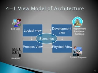
- 41. 41 Logical view Physical View Process View Development view End user System Engineer Integrator Programmers & software managers Scenarios
- 42. 42
- 43. 43
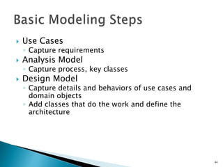
- 44. ´ü¢ Use Cases Ôùª Capture requirements ´ü¢ Analysis Model Ôùª Capture process, key classes ´ü¢ Design Model Ôùª Capture details and behaviors of use cases and domain objects Ôùª Add classes that do the work and define the architecture 44
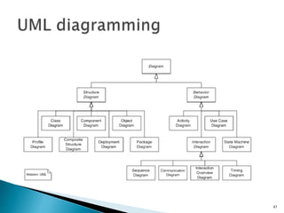
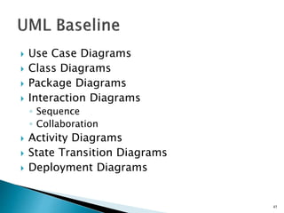
- 45. ´ü¢ Use Case Diagrams ´ü¢ Class Diagrams ´ü¢ Package Diagrams ´ü¢ Interaction Diagrams Ôùª Sequence Ôùª Collaboration ´ü¢ Activity Diagrams ´ü¢ State Transition Diagrams ´ü¢ Deployment Diagrams 45
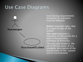
- 46. ´ü¢ Used during requirements elicitation to represent external behavior ´ü¢ Actors represent roles, that is, a type of user of the system ´ü¢ Use cases represent a sequence of interaction for a type of functionality; summary of scenarios ´ü¢ The use case model is the set of all use cases. It is a complete description of the functionality of the system and its environment 46 Passenger PurchaseTicket
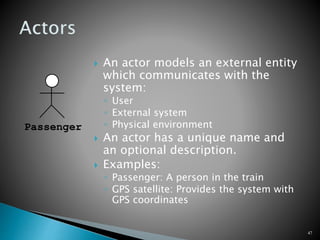
- 47. ´ü¢ An actor models an external entity which communicates with the system: Ôùª User Ôùª External system Ôùª Physical environment ´ü¢ An actor has a unique name and an optional description. ´ü¢ Examples: Ôùª Passenger: A person in the train Ôùª GPS satellite: Provides the system with GPS coordinates 47 Passenger
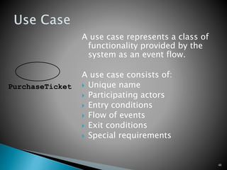
- 48. A use case represents a class of functionality provided by the system as an event flow. A use case consists of: ´ü¢ Unique name ´ü¢ Participating actors ´ü¢ Entry conditions ´ü¢ Flow of events ´ü¢ Exit conditions ´ü¢ Special requirements 48 PurchaseTicket
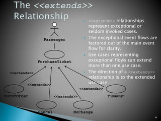
- 49. ´ü¢ <<extends>> relationships represent exceptional or seldom invoked cases. ´ü¢ The exceptional event flows are factored out of the main event flow for clarity. ´ü¢ Use cases representing exceptional flows can extend more than one use case. ´ü¢ The direction of a <<extends>> relationship is to the extended use case 49 Passenger PurchaseTicket TimeOut <<extends>> NoChange <<extends>> OutOfOrder <<extends>> Cancel <<extends>>
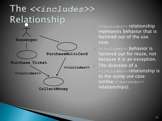
- 50. ´ü¢ <<includes>> relationship represents behavior that is factored out of the use case. ´ü¢ <<includes>> behavior is factored out for reuse, not because it is an exception. ´ü¢ The direction of a <<includes>> relationship is to the using use case (unlike <<extends>> relationships). 50 Passenger Purchase Ticket PurchaseMultiCard <<includes>> CollectMoney <<includes>>
- 51. ´ü¢ Determining requirements Ôùª New use cases often generate new requirements as the system is analyzed and the design takes shape. ´ü¢ Communicating with clients Ôùª Their notational simplicity makes use case diagrams a good way for developers to communicate with clients. ´ü¢ Generating test cases Ôùª The collection of scenarios for a use case may suggest a suite of test cases for those scenarios. 51
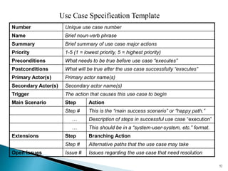
- 52. 52 Number Unique use case number Name Brief noun-verb phrase Summary Brief summary of use case major actions Priority 1-5 (1 = lowest priority, 5 = highest priority) Preconditions What needs to be true before use case executes Postconditions What will be true after the use case successfully executes Primary Actor(s) Primary actor name(s) Secondary Actor(s) Secondary actor name(s) Trigger The action that causes this use case to begin Main Scenario Step Action Step # This is the main success scenario or happy path.  Description of steps in successful use case execution  This should be in a system-user-system, etc. format. Extensions Step Branching Action Step # Alternative paths that the use case may take Open Issues Issue # Issues regarding the use case that need resolution Use Case Specification Template
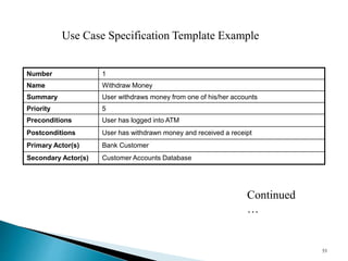
- 53. Number 1 Name Withdraw Money Summary User withdraws money from one of his/her accounts Priority 5 Preconditions User has logged into ATM Postconditions User has withdrawn money and received a receipt Primary Actor(s) Bank Customer Secondary Actor(s) Customer Accounts Database 53 Use Case Specification Template Example Continued 
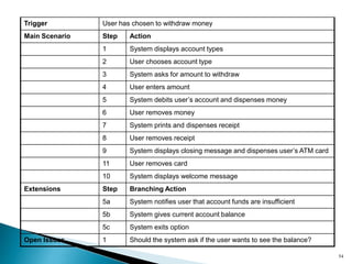
- 54. 54 Trigger User has chosen to withdraw money Main Scenario Step Action 1 System displays account types 2 User chooses account type 3 System asks for amount to withdraw 4 User enters amount 5 System debits userÔÇÖs account and dispenses money 6 User removes money 7 System prints and dispenses receipt 8 User removes receipt 9 System displays closing message and dispenses userÔÇÖs ATM card 11 User removes card 10 System displays welcome message Extensions Step Branching Action 5a System notifies user that account funds are insufficient 5b System gives current account balance 5c System exits option Open Issues 1 Should the system ask if the user wants to see the balance?
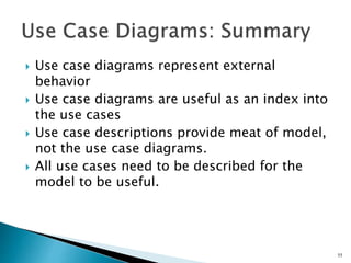
- 55. ´ü¢ Use case diagrams represent external behavior ´ü¢ Use case diagrams are useful as an index into the use cases ´ü¢ Use case descriptions provide meat of model, not the use case diagrams. ´ü¢ All use cases need to be described for the model to be useful. 55
- 56. 56