


unit 4 part 2.pptxvghjjjhjhhhhhhhhhhggggg
- 1. Signal Transmission Through LTI systems Unit iv part 2
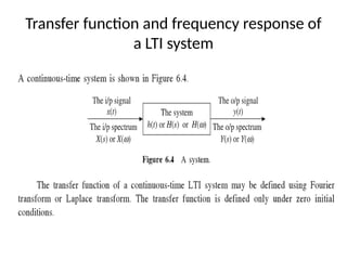
- 2. Filter Characteristics of Linear Systems ŌĆó For a given System an input Signal x(t) gives rise to a response signal y(t). ŌĆó The Spectral Density Function of the input S/L x(t) is given by X(s) or X(ß┐│) and The Spectral Density Function of the input S/L y(t) is given by Y(s) or Y(ß┐│) ŌĆó Y(s)=H(s) X(s) or Y(ß┐│)= H(ß┐│) X(ß┐│) ŌĆó If the System modifies the spectral density function of the input . The system acts a kind of filter for various frequency components.
- 3. ŌĆó Some frequency components are boosted in strength i.e., they are amplified. Some frequency components are weakened in strength i.e., they are attenuated and some may remain unaffected. ŌĆó The system modifies the spectral density function of the input according to filter characteristics. ŌĆó The modification is carried out according to the T/F H(s)or H(ß┐│) which represents the response of the system to various components. H(ß┐│) acts as a spectral shaping function to the different frequency components in the input signal. ŌĆó An LTI system, therefore acts as a filter. A filter is basically a frequency selective network.
- 4. ŌĆó Some LTI Systems allow the transmission of only low frequency components and stop all high frequency components. They are called LPFs. ŌĆó Some LTI Systems allow the transmission of only high frequency components and stop all low frequency components. They are called HPFs. ŌĆó Some LTI Systems allow the transmission of only particular band of frequencies and stop all other frequency components. They are called BPFs.
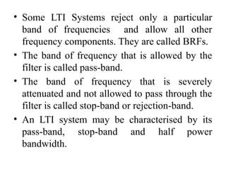
- 5. ŌĆó Some LTI Systems reject only a particular band of frequencies and allow all other frequency components. They are called BRFs. ŌĆó The band of frequency that is allowed by the filter is called pass-band. ŌĆó The band of frequency that is severely attenuated and not allowed to pass through the filter is called stop-band or rejection-band. ŌĆó An LTI system may be characterised by its pass-band, stop-band and half power bandwidth.
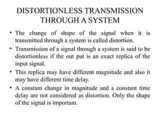
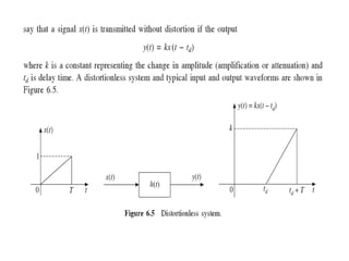
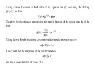
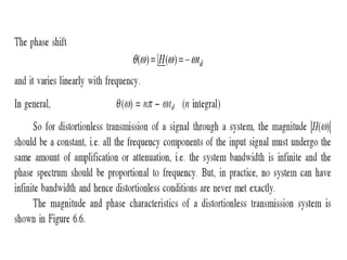
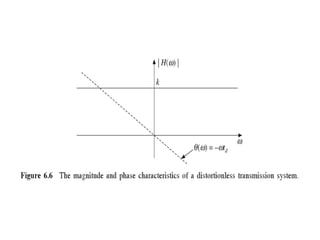
- 6. DISTORTIONLESS TRANSMISSION THROUGH A SYSTEM ŌĆó The change of shape of the signal when it is transmitted through a system is called distortion. ŌĆó Transmission of a signal through a system is said to be distortionless if the out put is an exact replica of the input signal. ŌĆó This replica may have different magnitude and also it may have different time delay. ŌĆó A constant change in magnitude and a constant time delay are not considered as distortion. Only the shape of the signal is important.
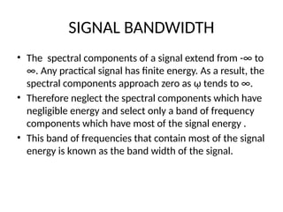
- 14. SIGNAL BANDWIDTH ŌĆó The spectral components of a signal extend from -Ōł× to Ōł×. Any practical signal has finite energy. As a result, the spectral components approach zero as ß┐│ tends to Ōł×. ŌĆó Therefore neglect the spectral components which have negligible energy and select only a band of frequency components which have most of the signal energy . ŌĆó This band of frequencies that contain most of the signal energy is known as the band width of the signal.
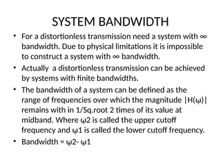
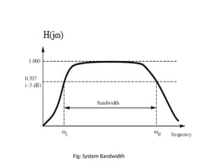
- 15. SYSTEM BANDWIDTH ŌĆó For a distortionless transmission need a system with Ōł× bandwidth. Due to physical limitations it is impossible to construct a system with Ōł× bandwidth. ŌĆó Actually a distortionless transmission can be achieved by systems with finite bandwidths. ŌĆó The bandwidth of a system can be defined as the range of frequencies over which the magnitude |H(ß┐│)| remains with in 1/Sq.root 2 times of its value at midband. Where ß┐│2 is called the upper cutoff frequency and ß┐│1 is called the lower cutoff frequency. ŌĆó Bandwidth = ß┐│2- ß┐│1
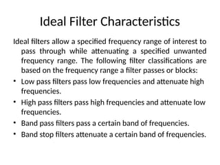
- 17. Ideal Filter Characteristics Ideal filters allow a specified frequency range of interest to pass through while attenuating a specified unwanted frequency range. The following filter classifications are based on the frequency range a filter passes or blocks: ŌĆó Low pass filters pass low frequencies and attenuate high frequencies. ŌĆó High pass filters pass high frequencies and attenuate low frequencies. ŌĆó Band pass filters pass a certain band of frequencies. ŌĆó Band stop filters attenuate a certain band of frequencies.
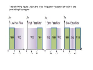
- 18. The following figure shows the ideal frequency response of each of the preceding filter types:
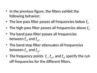
- 19. ŌĆó In the previous figure, the filters exhibit the following behavior: ŌĆó The low pass filter passes all frequencies below fc. ŌĆó The high pass filter passes all frequencies above fc. ŌĆó The band pass filter passes all frequencies between fc1 and fc2. ŌĆó The band stop filter attenuates all frequencies between fc1 and fc2. ŌĆó The frequency points fc , fc1, and fc2 specify the cut- off frequencies for the different filters.
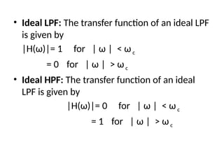
- 20. ŌĆó Ideal LPF: The transfer function of an ideal LPF is given by |H(Žē)|= 1 for | Žē | < Žēc = 0 for | Žē | > Žēc ŌĆó Ideal HPF: The transfer function of an ideal LPF is given by |H(Žē)|= 0 for | Žē | < Žēc = 1 for | Žē | > Žēc
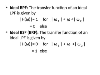
- 21. ŌĆó Ideal BPF: The transfer function of an ideal LPF is given by |H(Žē)|= 1 for | Žē1 | < Žē <| Žē2 | = 0 else ŌĆó Ideal BSF (BRF): The transfer function of an ideal LPF is given by |H(Žē)|= 0 for | Žē1 | < Žē <| Žē2 | = 1 else
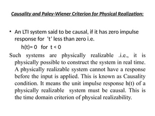
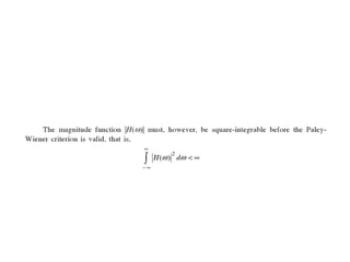
- 22. Causality and Paley-Wiener Criterion for Physical Realization: ŌĆó An LTI system said to be causal, if it has zero impulse response for ŌĆśtŌĆÖ less than zero i.e. h(t)= 0 for t < 0 Such systems are physically realizable .i.e., it is physically possible to construct the system in real time. A physically realizable system cannot have a response before the input is applied. This is known as Causality condition. It means the unit impulse response h(t) of a physically realizable system must be causal. This is the time domain criterion of physical realizability.
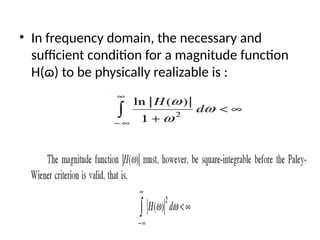
- 23. ŌĆó In frequency domain, the necessary and sufficient condition for a magnitude function H(╔Ę) to be physically realizable is :
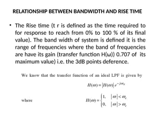
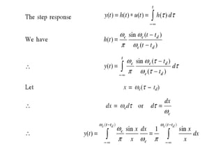
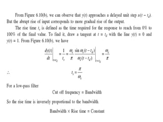
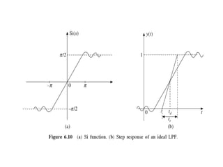
- 25. RELATIONSHIP BETWEEN BANDWIDTH AND RISE TIME ŌĆó The Rise time (t r is defined as the time required to for response to reach from 0% to 100 % of its final value). The band width of system is defined it is the range of frequencies where the band of frequencies are have its gain (transfer function H(Žē)) 0.707 of its maximum value) i.e. the 3dB points deference.
- 34. THE END
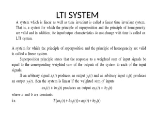
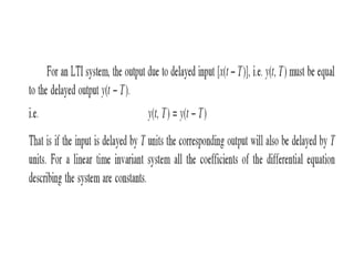
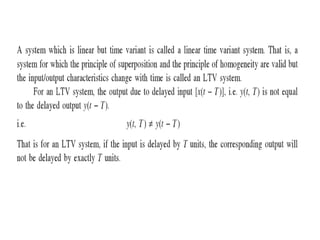
- 35. LTI SYSTEM
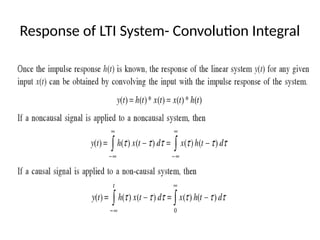
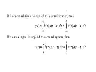
- 38. Response of LTI System- Convolution Integral
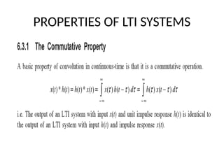
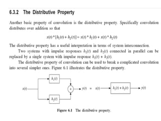
- 40. PROPERTIES OF LTI SYSTEMS
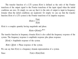
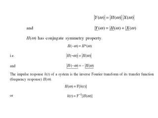
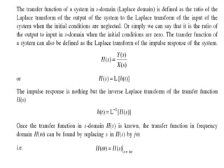
- 43. Transfer function and frequency response of a LTI system