Visit to 400 kV substation, Hadala
- 1. Visit to 400 kV substation Created by - NANDAN DESAI
- 2. Location : Hadala, Rajkot, Gujarat
- 3. Location : Hadala, Rajkot, Gujarat
- 4. ABOUT THE SUBSTATION ? The substation at Hadala (Rajkot), Gujarat is a 400 kV distribution substation. ? It receives power at 400 kV from Adani Thermal power plant via Varsana, from Mundra TPP via Chorania (Limbdi) and via Jetpur and from Varsana SS. ? It sends power at two voltage levels – 220 kV and 132 kV to Morbi, Nyara (Rajkot), Tappar, Gondal etc. ? The substation is connected as a ring system as Chorania (Limbdi) Amreli Jetpur Hadala (Rajkot) (Continue… )
- 5. (cont.) ? The substation is having two main bus and one transfer bus for both 400 kV side and 220 kV side. ? There are in total 6 lines of 400 kV level, 8+ lines of 220 kV and some lines of 132 kV level. ? It’s a record that there has been no accidents in this substation since last 2000+ days.
- 6. Equipments in substation ? Lightening arresters ? Wave trap ? Current Transformer (C.T.) ? Potential Transformer (P.T.) ? Line isolator with Earthing switch ? SF6 Circuit breaker with starting resistance ? Bus isolator ? 3 phase reactor (cont.)
- 7. Equipments in substation ? Power transformers ? Cables trench & tray ? Fire fighting facility
- 8. LIGHTENING ARRESTER ? The lightening arresters (L.A.) are used to ground the high voltage impulse falling on line during lightening. ? L.A. of all the lines connected to a bus are connected in parallel in order to ensure the proper grounding of surge as well as to increase its life. ? The L.A. core is made up of Zinc Oxide (ZnO2). It acts as a non-linear resistance i.e. it offers a very high resistance during normal conditions and offers low resistance to the surge voltages. ? A ring type structure is attached to L.A. in order to reduce the corona effect.
- 9. WAVE TRAP ? A wave trap is used on those transmission lines which are equipped with PLCC (Power Line Carrier Communication). ? As the communication signal frequency is much different from line frequency and also the voltage level is too low, it is quite necessary to separate the power signal and communication signal. ? This task is performed by a wave trap which simply consists of L-C series and parallel filters.
- 10. INSTRUMENT TRANFORMERS ? The instrument transformers are: 1. Current Transformers (C.T.) – Used to measure phase current. 2. Potential Transformers (P.T.) – Used to measure phase to neutral voltage. ? In this substation at some places CVT (Capacitive Voltage Transformers) are used which does function of PT as well as assisting the Wave Trap. C.T. P.T.
- 11. LINE/BUS ISOLATORS Centre Break Isolator Double Break Isolator Pantograph type bus isolators
- 12. LINE/BUS ISOLATORS ? The line isolators are used to isolate the line (after the operation of opening C.B.) under maintenance from the healthy system which otherwise may get resulted in L- G fault. ? The bus isolators are used to isolate the bus under maintenance. ? In this substation normally line isolators were centre break type isolators while the bus isolators were either double break type OR pantograph type isolators. ? The disc type structure at the tips of centre break type isolator is to reduce the corona loss while they are open. (cont.)
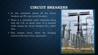
- 13. CIRCUIT BREAKERS ? In this substation almost all the circuit breakers are SF6 type circuit breakers. ? There is a switchable series resistance along with the C.B. as shown here. It is inserted while closing the circuit breakers for a short time. ? This resistor, hence, limits the charging current of the line’s stray capacitance.
- 14. 3 PHASE REACTOR ? The shunt reactors are used to absorb the excess of reactive power in the transmission lines. ? In this substation as long transmission lines are terminating in, their stray capacitance inject reactive power to absorb which, the reactor is installed here. ? The installed reactor is capable to reduce the line voltage by as much as 5 kV. ? In this substation, power lines coming from wind power station is also terminating. Since, there are large variations in the power production, their reactive power demand is also varying. Hence the reactor here is a switchable reactor.
- 15. POWER TRANSFORMER ? This substation has two type of power transformers: 1) 400 kV ? 220 kV and 2) 220 kV ? 132 kV ? The cooling system employed is forced air – forced oil. ? The cooling systems of transformers are automatically controlled. Once the temperature reaches 70? C, the cooling system starts and as temperature reaches 60 ? C, the systems switches OFF. ? The supply to the cooling system is given from the substation supply transformer. 400 kV transformer 220 kV to 132 kV transformer
- 16. CABLES TRENCH & TRAY ? The cables that collect the communication signals from instrument transformers, circuit breakers, isolators, wave traps etc. are made to run in cable trench towards the control room. ? The place where all the cables are collected is called cable tray.
- 17. FIRE FIGHTING FACILITY ? As oil is used as coolant and body insulator, there are possibilities of fire in case of short circuits. ? Fire fighting facility available in two ways in this substation. ? One way is that at some particular distance gaseous fire extinguishing cylinders are kept. ? Another is that a water pipe runs everywhere in substation. In case of fire, it sprinkles the water in surrounding area in fine molecular form in order to stop propagation of fire.
- 18. CONTROL ROOM & RELAY ROOM ? The control room has various control panels which shows the information like incoming power, outgoing power, frequency, time common to all substations, status of various lines (healthy, faulted, under outage or maintenance), status of various protective instruments like isolators, circuit breakers; temperatures of various instruments, working tap of transformers etc. ? The DAS (Data Acquisition System) is used to accumulate the data received from various sources. ? The relay room is separate from the control room. All relays used here are numerical and are either from Siemens? OR ABB? . ? The protection system is so fast that it can detect a fault within 30 ms and hence the circuit breaker can be operated within as less as 80 ms. ? For 400 kV side C.B., one time auto reclosure is allowed in order to clear the temporary faults automatically.
- 19. Control Room Relay Room
- 20. BATTERY ROOM ? The control panels and relays of the substation require DC supply of 220 V. ? This DC supply is made with the help of battery bank reserve normally kept in a separate room called Battery room. ? The batteries used in this substation are Nickel-Cadmium (Ni-Cd) batteries. These batteries are used due to their advantages like low maintenance, longer life (15-25 years) etc. ? Each cell is of 2 V and 6Ah capacity. ? The battery room and the battery chargers are shown in next slide.
- 21. BATTERY ROOM & ITS CHARGERS Battery Room Battery Chargers


