


More Related Content
What's hot (19)
Similar to Vn nvr operation and maintenance (v1.1) (20)


Vn nvr operation and maintenance (v1.1)
- 1. V?N H?NH V? B?O TR? NVR 2018 V 1.0 Overseas technical team
- 2. M?c ti¨şu B¨şn ngo¨¤i s?n ph?m V?n h¨¤nh B?o tr¨¬
- 3. Gi?i thi?u s?n ph?m01 H??ng d?n c¨¤i ??t02 M? h¨¬nh m?ng c? b?n03 D?ch v? c? b?n04 N?i dung 05 D?ch v? m? r?ng 06 B?o tr¨¬
- 4. Quy t?c ??t t¨şn NVR302-16E-P16 01: 1 SATA slot 02: 2 SATA slots 04: 4 SATA slots 08: 8 SATA slots 16: 16 SATA slots D¨°ng s?n phaarm ??u ghi IP 04: 4 K¨şnh 08: 8 K¨şnh 16: 16 K¨şnh 32: 32 K¨şnh 64: 64 K¨şnh 128: 128 K¨şnh Px: x C?ng PoE W: H? tr? WIFI E: N?ng cao L: V? nh?a Default/S: C? b?n R: Raid -B B: Th? h? th? 2
- 5. B¨şn ngo¨¤i d¨°ng s?n ph?m NVR301/302/304 (1) RUN (Ho?t ??ng) (2) NET (b¨˘o hi?u m?ng) (3) HD (b¨˘o tr?ng th¨˘i ? c?ng) (4) Cloud
- 6. B¨şn ngo¨¤i d¨°ng s?n ph?m NVR304EP/308E (1) C?ng USB (2) Ch? th? ph¨Şa tr??c (3) B?ng ?i?u khi?n
- 7. B¨şn ngo¨¤i d¨°ng s?n ph?m NVR316/516 (1) RUN (Ho?t ??ng) (2) C?NH B?O (3) M?NG (4) Cloud
- 8. Ph¨Şa sau s?n ph?m (NVR304EP-B)
- 9. Ph¨Şa sau s?n ph?m (NVR308R-B)
- 10. Ph¨Şa sau s?n ph?m (NVR516)
- 11. Gi?i thi?u s?n ph?m01 H??ng d?n c¨¤i ??t02 M? h¨¬nh m?ng c? b?n03 D?ch v? c? b?n04 N?i dung 05 D?ch v? m? r?ng 06 B?o tr¨¬
- 12. H??ng d?n c¨¤i ??t L?p ? c?ng Y¨şu c?u v? l?p ??t L?p ??t trong cabin
- 13. Y¨şu c?u v? l?p ??t ?Kh?ng ???c x?p ch?ng c¨˘c thi?t b? NVR l¨şn nhau ho?c ??t ? n?i nhi?t ?? cao. N?u kh?ng s? t?n nhi?t c¨® th? b? ?nh h??ng. ? Gi? thi?t b? NVR c?a b?n tr¨˘nh kh?i c¨˘c ngu?n xung; v¨Ş d? nh? m?t m¨˘y ph¨˘t ?i?n,. Kh?ng ?? s¨˘t NVR tr?c ti?p v?i lu?ng gi¨® m?nh nh? t? ?i?u h¨°a , qu?n ?i?n c?ng su?t l?n.
- 14. ?N?u trong m?t m?i tr??ng m¨¤ ngu?n hay b? m?t (hay m?t ?i?n), n¨şn s? d?ng b? ngu?n d? ph¨°ng UPS. ?H?y ch?c ch?n thi?t b? ???c n?i ??t ?¨˛ng c¨˘ch v¨¤ kh? n?ng ch?ng s¨¦t. Gi? thi?t b? tr¨˘nh b?i, b?c x?, xung m?nh t? ?i?n t? Y¨şu c?u v? l?p ??t
- 15. L?p ? c?ng
- 16. L?p ? c?ng
- 17. L?p ? c?ng d?ng khay tr??t
- 18. L?p ??t trong cabin t? rack 1: ?c v¨Şt 2: L? b?t 3: Tai g?n l¨şn gi¨˘ Ch?c ch?n r?ng cabinet (t? rack) ???c trang b? v?i m?t d?ng khay ho?c thanh tr??t tr??c khi l?p thi?t b? v¨¤o cabinet. Thi?t b? ph?i ???c h? tr? tai g?n ?? treo v¨¤o khay ho?c thanh tr??t c?a t? rack
- 19. Gi?i thi?u s?n ph?m01 H??ng d?n c¨¤i ??t02 M? h¨¬nh m?ng c? b?n03 D?ch v? c? b?n04 N?i dung 05 D?ch v? m? r?ng 06 B?o tr¨¬
- 20. NVR k?t n?i ??n IPC Switch PC IPC1 IPC8 ˇˇ. IPC1 ˇˇ. NVR IPCN Monitor M?ng: LAN ?ng d?ng : SOHO (V?n ph¨°ng nh?, c?a h¨¤ng)
- 21. NVR k?t n?i ??n EZSTATION M?ng: LAN ?ng d?ng: Kh¨˘ch s?n/ th??ng m?iˇetc. Switch EZStation NVR IPC8 IPC1 ˇˇ. NVR IPC Monitor
- 22. NVR truy c?p qua EZCloud M?ng: WAN ?ng d?ng : C?a h¨¤ng b¨˘n l?/ Nh¨¤ ?/ C?n h? etc. 3GÍřÂç phone1 Internet NVR phone2 Web EZCloud IPC1 IPC8 IPC
- 23. ?ng d?ng th?ng th??ng NH? ? B?N L? C?N H? CAO C?P TRUNG T?M TH??NG M?I
- 24. Gi?i thi?u s?n ph?m01 H??ng d?n c¨¤i ??t02 M? h¨¬nh m?ng c? b?n03 D?ch v? c? b?n04 N?i dung 05 D?ch v? m? r?ng 06 B?o tr¨¬
- 25. D?ch v? c? b?n C¨¤i ??t c? b?n K?t n?i IPC C¨¤i ??t ghi h¨¬nh Xem l?i v¨¤ t?i xu?ng
- 26. C¨¤i ??t c? b?n - ??ng nh?p V?i l?n ??u ??ng nh?p. ??a ch? m?c ??nh c?a ??u ghi l¨¤ 192.168.1.30, t¨şn ng??i d¨´ng m?c ??nh l¨¤ ˇ®ˇŻadminˇŻˇŻ v¨¤ m?t kh?u m?c ??nh l¨¤ ˇ®ˇŻ123456ˇŻˇŻ
- 27. C¨¤i ??t c? b?n - ??ng nh?p M?t kh?u m?c ??nh ???c s? d?ng ch? cho l?n ??ng nh?p ??u ti¨şn v¨¤ n¨şn thay ??i n¨® th¨¤nh m?t kh?u m?nh bao g?m ¨Şt nh?t 8 k? t? g?m ch? hoa v¨¤ ch? th??ng, k? t? ??c bi?t sau l?n ??u ??ng nh?p ?? ??m b?o ?? an to¨¤n.
- 28. C¨¤i ??t c? b?n ¨C Giao di?n Web Giao di?n Web c?a NVR g?m 4 ph?n: Menu, danh s¨˘ch thi?t b?, c?a s? xem tr?c ti?p, thanh ?i?u khi?n xem tr?c ti?p. M?t g¨®i tinT?c ?? khung h¨¬nhB? c?c m¨¤n h¨¬nh ?? ph?n gi?i Ki?u lu?ng T?c ?? Bit ??nh d?ng m? h¨®a Ch?p h¨¬nh Ph¨®ng ??i s? M?t c¨˘ ?m thanh 2 chi?u To¨¤n m¨¤n h¨¬nh Xem l?i ?m thanh?i?u khi? PTZ 3D position
- 29. C¨¤i ??t c? b?n ¨C Th?i gian ? C¨¤i ??t th?i gian th? c?ng ho?c t? ??ng ? C¨¤i ??t th?i gian b?ng ??ng b? v?i PC b?ng c¨˘ch ?n v¨¤o n¨˛t ˇ°Sync with PCˇŻˇŻ Vui l¨°ng ch?n T? ??ng c?p nh?t tr??c n?u b?n mu?n s? d?ng m¨˘y ch? NTP ?? ??ng b? th?i gian NVR.
- 30. C¨¤i ??t c? b?n¨C ??ng b? th?i gian NVR1 NVR2 ??ng b? th?i gian camera B?T ??ng b? th?i gian camera T?T ? S? d?ng ch?c n?ng n¨¤y ?? ??ng b? th?i gian camera v?i NVR. ? Ch?c n?ng ??ng b? th?i gian n¨¤y ???c m?c ??nh B?t. ? Camera s? ??ng b? th?i gian v?i NVR sau khi online v¨¤ ti?p theo n¨® s? ??ng b? 30 ph¨˛t m?t l?n.
- 31. C¨¤i ??t c? b?n ¨C TCP/IP ? Ch? ?? ?a ??a ch? 2 NIC l¨¤m vi?c ??c l?p v¨¤ c¨® th? ???c c?u h¨¬nh t¨˘ch bi?t nhau. Hai ??a ch? IP cho vi?c k?t n?i ??n 2 m?ng kh¨˘c nhau (m?t cho m?ng LAN, v¨¤ m?t cho k?t n?i t? xa) M?i NIC c¨® th? ???c ch?n nh? l¨¤m m?t ??nh tuy?n m?c ??nh v¨¤ d? li?u s? ???c chuy?n ti?p th?ng qua NIC n¨¤y khi NVR k?t n?i ??n m?ng l??i.
- 32. C¨¤i ??t c? b?n ¨C TCP/IP ? Ch? ?? c?n b?ng t?i Hai NIC ???c r¨¤ng bu?c v?i nhau ?? khi l¨¤m vi?c c¨´ng nhau n¨® th? th? chia s? l?u l??ng m?ng v?i nhau.
- 33. C¨¤i ??t c? b?n ¨C TCP/IP ? Ch? ?? h? tr? khi m?ng l?i Hai NIC ???c r¨¤ng bu?c ?? c¨´ng d?i ??a ch? IP. Trong tr??ng h?p m?t NIC l?i, c¨˘i c¨°n l?i s? ti?p nh?n c?ng vi?c c?a c¨˘i l?i ?? ??m b?o m?ng ho?t ??ng b¨¬nh th??ng.
- 34. C¨¤i ??t c? b?n ¨C PPPoE Nh?p v¨¤o t¨şn ng??i d¨´ng v¨¤ m?t kh?u ???c cung c?p b?i nh¨¤ m?ng Internet (ISP) Th?ng tin m?ng bao g?m ??a ch? IP xu?t hi?n khi k?t n?i th¨¤nh c?ng
- 35. C¨¤i ??t c? b?n ¨C OSD OSD(Hi?n th? tr¨şn m¨¤n h¨¬nh) ? Th?i gian ? ??a ?i?m ? T¨şn camera ? Th?ng tin kh¨˘c
- 36. C¨¤i ??t c? b?n ¨C M? h¨®a
- 37. ?Th¨şm b?ng c¨˘ch t? ??ng t¨¬m thi?t b? ?Th¨şm b?ng c¨˘ch t¨¬m theo d?i ??a ch? ?Th¨şm th? c?ng T? kh¨®a ? ??a ch? IP /EZDDNS/ T¨şn mi?n ? C?ng ? T¨şn ng??i d¨´ng ? M?t kh?u K?t n?i IP
- 38. K?t n?i IP ¨C G¨˘n th? c?ng b?ng Uniview Giao th?c Uniview ???c khuy?n ngh? s? d?ng khi b?n s? d?ng s?n ph?m UNV, n?u kh?ng th¨¬ m?t v¨¤i ch?c n?ng s? kh?ng ho?t ??ng, v¨Ş d? nh? ch?c n?ng VCA.
- 39. K?t n?i IP ¨C G¨˘n th? c?ng qua ONVIF Giao th?c ONVIF ???c khuy?n ngh? s? d?ng khi b?n g¨˘n camera IP b¨şn th? 3.
- 40. K?t n?i IP ¨C G¨˘n th? c?ng qua RTSP S? d?ng c¨˘ch n¨¤y ch? khi thi?t b? IP th¨şm v¨¤o c¨® h? tr? chu?n giao th?c RTSP Ch¨˛ ?: Ch? c¨® xem tr?c ti?p v¨¤ xem l?i ho?t ??ng ???c khi g¨˘n IP b?ng RTSP
- 41. K?t n?i IP ¨C G¨˘n th?ng qua t? ??ng t¨¬m ki?m NVR s? t? ??ng t¨¬m ??a ch? IP c?a thi?t b? v¨¤ danh s¨˘ch t¨¬m th?y khi b?n ch?n ch? ?? n¨¤y
- 42. K?t n?i IP ¨C G¨˘n qua d?i ??a ch? IP
- 43. K?t n?i IP ¨C G¨˘n qua ONVIF V?i M¨˘y ch? video k? thu?t s? (DVS), m?t c?a s? xu?t hi?n khi b?n click Th¨şm, v¨¤ b?n c?n ch?n c¨˘c k¨şnh ?? g¨˘n. Ch¨˛ ?: C?ng UNV DVS ONVIF l¨¤ 82
- 44. Fisheye (4K) Ch? c¨® 3 NVR lo?i 2HDD ho?c h?n v¨¤ NVR516 h? tr? g¨˘n camera fisheye.
- 45. Fisheye (4K) 4K Fisheye c?ng h? tr? giao di?n Web/Gui ?? ?i?u khi?n th?ng qua d¨°ng B NVR.
- 46. Fisheye (4MP)
- 47. D?ch v? c? b?n ¨C ? C?ng Xem th?ng tin v? ? c?ng, bao g?m t?ng dung l??ng, dung l??ng c¨°n tr?ng, tr?ng th¨˘i ? c?ng, ki?u ? c?ng, ? c?ng d¨´ng cho vi?c g¨¬, ??c t¨Şnh ? c?ng. Ch? c¨® quy?n Admin m?i c¨® th? x¨®a ? v¨¤ ph?n quy?n ki?u ??c/ghi cho ?
- 48. D?ch v? c? b?n ¨C ? C?ng ??c/ghi: ? c?ng ???c s? d?ng cho ghi h¨¬nh v¨¤ xem l?i. Ch? ??c: ? c?ng ch? s? d?ng cho xem l?i D? ph¨°ng: ? c?ng d¨´ng cho ghi d? ph¨°ng, nh?ng b?n c?u h¨¬nh l?ch ghi th¨¬ b?n n¨şn b?t ch? ?? n¨¤y
- 49. D?ch v? c? b?n ¨C ? C?ng Ch? ??nh ? c?ng ?? v¨¤o 1 nh¨®m v¨¤ s? d?ng nh¨®m ? c?ng cho l?u tr? v¨¤ ?nh ch?p c?a camera ???c quy ??nh. Khay kh¨˘c nhau c¨® th? ???c ch? ??nh nh¨®m kh¨˘c nhau.
- 50. D?ch v? c? b?n ¨C ? C?ng Ph?n b? kh?ng gian cho l?u video v¨¤ ?nh c?a camera ???c quy ??nh.
- 51. D?ch v? c? b?n ¨C ? C?ng Ghi ?¨¨: b?n ghi/ ?nh ch?p c? nh?t s? b? ghi ?¨¨ khi kh?ng gian l?u tr? h?t. D?ng: B?n ghi m?i v¨¤ ?nh ch?p c?a camera s? kh?ng ???c l?u khi kh?ng gian l?u tr? h?t.
- 52. D?ch v? c? b?n ¨C L?ch ghi ? B?n c¨® th? ??t l?ch, chuy?n ??ng, c?nh b¨˘o, M ho?c A, M v¨¤ A trong danh s¨˘ch. ? L?ch ghi A 24ˇÁ7???c b?t m?c ??nh v¨¤ c¨® th? ???c ch?nh s?a khi c?n thi?t ?? ghi ch? trong c¨˘c kho?ng th?i gian ???c ch? ??nh.
- 53. D?ch v? c? b?n ¨C Xem l?i L?ch xem l?i ???c g?n c? kh¨˘c nhau ?? ch? ch? c¨˘c ki?u ghi kh¨˘c nhau. Kh?ng g?n c? ngh?a l¨¤ kh?ng c¨® file ghi. C? xanh ngh?a l¨¤ ghi th?ng th??ng. C? ?? ngh?a l¨¤ ghi theo k¨Şch ho?t s? ki?n. C? v¨¤ng ngh?a l¨¤ ghi kh?ng ho¨¤n th¨¤nh.
- 54. D?ch v? c? b?n ¨C Xem l?i ?T?c ?? cao: T?c ?? bit lu?ng l?u tr? 8x ?T?c ?? th??ng: T?c ?? bit lu?ng l?u tr? 1x
- 55. Gi?i thi?u s?n ph?m01 H??ng d?n c¨¤i ??t02 M? h¨¬nh m?ng th?ng th??ng03 D?ch v? c? b?n04 Content 05 D?ch v? m? r?ng 06 B?o tr¨¬
- 56. ?i?u khi?n & EZCloud C?nh b¨˘o & VCA An ninh m?ng D?ch v? m? r?ng
- 57. D?ch v? m? r?ng ¨C Truy c?p t? xa & EZCloud ?? s? d?ng UPnP trong thi?t b?, b?n ph?i b?t UPnP trong Router (b? ??nh tuy?n) c¨˘i m¨¤ thi?t b? c?a b?n k?t n?i ??n. Ch? ?? t? ??ng ???c khuy?n ngh? s? d?ng,n?u th?ng th¨¬ c¨˘c port (c?ng) s? xung ??t n?u c?u h¨¬nh kh?ng ?¨˛ng ? UPNP Ch? ?? t? ??ng
- 58. D?ch v? m? r?ng ¨C Truy c?p t? xa & EZCloud ?UPNP Ch? ?? th? c?ng N?u b?n mu?n quy ??nh port ngo¨¤i, b?n ph?i ch?n th? c?ng UPnP. ??i v?i m?t NVR v?i nhi?u NIC, port mapping n¨şn ???c c?u h¨¬nh d?a tr¨şn NIC quy ??nh nh? ??nh tuy?n m?c ??nh.
- 59. D?ch v? m? r?ng ¨C Truy c?p t? xa & EZCloud ? Port forwarding (C?ng chuy?n ti?p) th? c?ng tr¨şn b? ?inh tuy?n Router N?u b? ??nh tuy?n c?a b?n kh?ng h? tr? UPnP, ti?p theo b?n c¨® th? c?u h¨¬nh th? c?ng port n?i m?ng v¨¤ port ra ngo¨¤i. B??c 1: Ch?n th? c?ng ch? ?? C?ng chuy?n ti?p. Ch?n ch? ?? th? c?ng b¨şn trong Ch? ?? Mapping, ??t port n?i m?ng th? c?ng.
- 60. D?ch v? m? r?ng ¨C Truy c?p t? xa & EZCloud ? Port forwarding (C?ng chuy?n ti?p) th? c?ng tr¨şn b? ?inh tuy?n Router B??c 2: c¨¤i ??t c?ng chuy?n ti?p tr¨şn b? ??nh tuy?n Nguy¨şn l? c?a port mapping l¨¤ c?ng n?i v¨¤ c?ng ngo?i c?a NVR ph?i th¨Şch h?p v?i n¨® c?a b? ??nh tuy?n.
- 61. D?ch v? m? r?ng ¨C Truy c?p t? xa & EZCloud ? Port forwarding (C?ng chuy?n ti?p) th? c?ng tr¨şn b? ?inh tuy?n Router M?t v¨¤i b? ??nh tuy?n y¨şu c?u c?ng n?i v¨¤ ngo¨¤i l¨¤ gi?ng nhau v?i c? NVR v¨¤ b? ??nh tuy?n.
- 62. D?ch v? m? r?ng ¨C Truy c?p t? xa & EZCloud ? ??ng k? NVR l¨şn EZCloud
- 63. VCA v¨¤ c?nh b¨˘o Motion Detection Cross Line Intrusion Face Detection People Counting Auto Tracking Scene Change Defocus Detection Audio Detection Tampering Alarm 0 / 1 Email Alarm Signal Output RecordSnapshot Upload to FTP FTP Preset Li¨şn k?t k¨Şch ho?t (t¨´y ch?n)
- 64. D?ch v? m? r?ng ¨C Chuy?n ??ng Khi ???c b?t, m?t c?nh b¨˘o chuy?n ??ng x?y ??n n?u ??i t??ng b¨şn trong v¨´ng ph¨˘t hi?n di chuy?n ? m?c ?? nh?t ??nh.
- 65. D?ch v? m? r?ng ¨C Chuy?n ??ng ? C? ng¨¤y ???c b?t m?c ?inh ? B?n ph?i ch?n 8 chu k¨¬ cho m?i ng¨¤y ? ?? ¨˘p d?ng l?ch cho ng¨¤y kh¨˘c, ch?n ng¨¤y v¨¤ ch?n ˇ®ˇŻCopy ToˇŻˇŻ
- 66. D?ch v? m? r?ng ¨C Chuy?n ??ng Ph¨˘t hi?n chuy?n ??ng c¨® th? k¨Şch ho?t c¨˘c h¨¤nh ??ng bao g?m: ?m c?nh b¨˘o, g?i Email, ghi h¨¬nh, ch?p h¨¬nh, k¨Şch ho?t ng? ra.
- 67. D?ch v? m? r?ng ¨C Gi? m?o Ph¨˘t hi?n gi? m?o khi ?ng k¨Şnh camera b? che ph? b?i ai ?¨®
- 68. D?ch v? m? r?ng ¨C M?t video M?t c?nh b¨˘o m?t video x?y ra khi NVR m?t t¨Şn hi?u k?t n?i t? camera. T¨Şnh n?ng n¨¤y m?c ??nh ???c b?t tr¨şn NVR
- 69. D?ch v? m? r?ng ¨C C?nh b¨˘o ?m thanh M?t c?nh b¨˘o ph¨˘t hi?n ?m thanh khi m?t camera ph¨˘t hi?n s? thay ??i ?m thanh m?t c¨˘ch ??t ng?t.
- 70. D?ch v? m? r?ng ¨C VCA ?Ph¨˘t hi?n khu?n m?t Ph¨˘t hi?n khu?n m?t ???c s? d?ng ?? ph¨˘t hi?n khu?n m?t con ng??i trong m?t v¨´ng gi¨˘m s¨˘t.
- 71. D?ch v? m? r?ng ¨C VCA ?Ph¨˘t hi?n x?m nh?p Ph¨˘t hi?n x?m nh?p ???c s? d?ng ?? ph¨˘t hi?n ??i t??ng di chuy?n v¨¤o v¨´ng quy ??nh v¨¤ k¨Şch ho?t h¨¤nh ??ng c?n thi?t.
- 72. D?ch v? m? r?ng ¨C VCA ?Ph¨˘t hi?n v??t h¨¤ng r¨¤o ?o Ph¨˘t hi?n v??t h¨¤ng r¨¤o ?o ???c s? d?ng ?? ph¨˘t hi?n b?t k? ??i t??ng n¨¤o v??t v?ch k? ?o tr¨şn m¨¤n h¨¬nh v¨¤ k¨Şch hoat c?nh b¨˘o c?n thi?t.
- 73. D?ch v? m? r?ng ¨C VCA ?Ph¨˘t hi?n m?t l?y n¨¦t v¨¤ thay ??i c?nh D¨´ng t¨Şnh n?ng ph¨˘t hi?n m?t l?y n¨¦t ?? ki?m tra camera c¨® l?y n¨¦t ?¨˛ng kh?ng. D¨´ng t¨Şnh n?ng thay ??i c?nh ?? ph¨˘t hi?n s? thay ??i m?i tr??ng gi¨˘m s¨˘t do nguy¨şn nh?n s? thay ??i c?a y?u t? b¨şn ngo¨¤i nh? s? c? ? xoay camera.
- 74. D?ch v? m? r?ng ¨C VCA ? ??m ng??i ??m ng??i ???c s? d?ng ?? ??m s? l??ng ng??i ra/v¨¤o m?t v¨´ng. Ch¨˛ ?: T¨Şnh n?ng n¨¤y kh?ng ???c s? d?ng ??ng th?i v?i c¨˘c t¨Şnh n?ng VCA kh¨˘c.
- 75. D?ch v? m? r?ng ¨C T¨¬m ki?m VCA T¨¬m ki?m d? li?u VCA bao g?m h¨¤nh vi, khu?n m?t, ??m g??i T¨¬m ki?m h¨¤nh vi: S? d?ng ?? t¨¬m ki?m b?n ghi ???c k¨Şch ho?t khi ph¨˘t hi?n c¨˘c h¨¤nh vi nh? v??t h¨¤ng r¨¤o ?o v¨¤ x?m nh?p.
- 76. D?ch v? m? r?ng ¨C T¨¬m ki?m VCA T¨¬m ki?m khu?n m?t: S? d?ng ?? t¨¬m ki?m c¨˘c k¨Şch ho?t ghi h¨¬nh khi ph¨˘t hi?n khu?n m?t ?? xem l?i video khi khu?n m?t ???c ph¨˘t hi?n ( kho?ng 10s tr??c v¨¤ sau khi ph¨˘t hi?n), click v¨¤o n¨˛t Play, h¨¬nh b¨şn d??i l¨¤ v¨Ş d?:
- 77. D?ch v? m? r?ng ¨C T¨¬m ki?m VCA ??m ng??i: Ki?m tra ???c l??ng ng??i ra/v¨¤o v¨´ng quy ??nh theo chu k? ng¨¤y/tu?n/n?m B?n c¨® th? ch?n ki?u hi?n th? k?t qu? d?ng b?ng ho?c bi?u ?? nh? h¨¬nh b¨şn d??i
- 78. D?ch v? m? r?ng ¨C Email NVR c¨® th? c¨¤i ??t ?? g?i m?t email th?ng b¨˘o quy ??nh ??n ??a ch? email n¨¤o ?¨® khi m?t c?nh b¨˘o xu?t hi?n. N?i dung Email s? bao g?m th?ng tin nh? l¨¤ lo?i c?nh b¨˘o, th?i gian c?nh b¨˘o, camera ID, v¨¤ t¨şn cameraˇ.
- 79. An ninh m?ng 802.1x User Account HTTPS ONVIF Auth ARP Protection IP Control Telnet Security Password Watermark
- 80. An ninh m?ng ¨C qu?n l? ng??i d¨´ng ? M?t quy?n admin c¨® th? th¨şm v¨¤ x¨®a c¨˘c ng??i d¨´ng v¨¤ ??t ph?n quy?n cho ng??i dung kh¨˘c.
- 81. An ninh m?ng ¨C ?i?u khi?n IP NVR ch? cho ph¨¦p ???c truy c?p t? c¨˘c ??a ch? IP trong danh s¨˘ch NVR c?m truy c?p t? danh s¨˘ch IP b? c?m c?a n¨®
- 82. An ninh m?ng ¨C HTTPS & Watermark Ho?t ??ng m? h¨®a d? li?u M? h¨®a lu?ng d? li?u Video
- 83. An ninh m?ng ¨C M?t kh?u an to¨¤n ?M?t kh?u th??ng: B?n n¨şn ??ng nh?p v?i m?t kh?u m?nh trong c¨´ng d?i m?ng ho?c 3 d?i m?ng ri¨şng (10.0.0.0/8, 172.16.0.0/12, 192.168.0.0/24) ?M?t kh?u n?ng cao: B?n bu?c ph?i ??ng nh?p v?i m?t kh?u m?nh
- 84. An ninh m?ng ¨C ONVIF Auth & Telnet Ch¨˛ ?: N?u b?t t¨Şnh n?ng n¨¤y, n¨® s? y¨şu c?u nh?p t¨şn ng??i d¨´ng v¨¤ m?t kh?u ?? truy c?p qua ONVIF (khi truy c?p t? n?n t?ng kh¨˘c) Telnet m?c ??nh ???c t?t
- 85. An ninh m?ng ¨C ARP Protection & 802.1x 802.1x Control port
- 86. Gi?i thi?u s?n ph?m01 H??ng d?n c¨¤i ??t02 M? h¨¬nh m?ng th?ng th??ng03 D?ch v? c? b?n04 N?i Dung 05 D?ch v? m? r?ng 06 B?o tr¨¬
- 87. B?o tr¨¬ ¨C Truy xu?t nh?t k? B?o tr¨¬ bao g?m vi?c truy xu?t nh?t k?, th?ng tin S.M.A.R.T. , n?ng c?p, th?ng tin ph?n t¨Şch, thi?t l?p m?c ??nh thi?t b?,kh?i ??ng l?i.
- 88. B?o tr¨¬ ¨C Truy xu?t nh?t k? Nh?t k? bao g?m th?ng tin v? h¨¤nh ??ng c?a ng??i dung v¨¤ tr?ng th¨˘i thi?t b?. B?ng vi?c ph?n t¨Şch nh?t k?, b?n c¨® th? theo d?i tr?ng th¨˘i ho?t ??ng c?a thi?t b? v¨¤ xem chi ti?t c¨˘c th?ng tin c?nh b¨˘o.
- 89. B?o tr¨¬ ¨C Tr?ng th¨˘i c?ng PoE
- 90. B?o tr¨¬ ¨C Th?ng k¨ş th?ng s? m?ng Th?ng k¨ş th?ng s? v? m?ng c¨® th? ki?m tra c¨˘c th?ng s? v? b?ng th?ng.
- 91. B?o tr¨¬ ¨C HDD S.M.A.R.T: S? d?ng ?? ki?m tr?ng th¨˘i c?a ? c?ng. Ki?m tra ph?n v¨´ng l?i: C¨® th? ki?m tra n?u c¨˘c ph?n v¨´ng HDD x?y ra l?i.
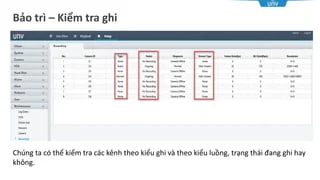
- 92. B?o tr¨¬ ¨C Ki?m tra ghi Ch¨˛ng ta c¨® th? ki?m tra c¨˘c k¨şnh theo ki?u ghi v¨¤ theo ki?u lu?ng, tr?ng th¨˘i ?ang ghi hay kh?ng.
- 93. B?o tr¨¬ ¨C th?ng tin ph?n t¨Şch ?i?u n¨¤y r?t quan tr?ng ?? thu th?p th?ng tin ph?n t¨Şch c¨˘i m¨¤ gi¨˛p x¨˘c nh?n c?u h¨¬nh c?a thi?t b? v¨¤ v?n ?? c?a n¨®.
- 94. B?o tr¨¬ ¨C n?ng c?p ? N?ng c?p n?i b? qua Web: n?ng c?p s? d?ng m?t file ???c l?u tr¨şn USB ho?c tr¨şn PC. ? N?ng c?p qua Cloud: N?ng c?p th?ng qua m¨˘y ch? Cloud. Ch¨˛ ?: NVR h? tr? NTFS v¨¤ FAT32 ?? sao l?u , t?i ?a l¨¤ 2TB
- 95. H?i ?¨˘p N?u t?i xu?ng ActiveX l?i khi b?n ??ng nh?p v¨¤o Web th¨¬ b?n ph?i l¨¤m g¨¬?
- 96. H?i ?¨˘p L¨¤m c¨˘ch n¨¤o ?? l?y l?i m?t kh?u NVR? ? L?y l?i m?t kh?u b?ng EZCloud ˇľ?i?u khi?nˇż NVR ph?i ?? ???c ??ng k? l¨şn EZCloud ˇľChi ti?tˇż B??c 1Łş??ng nh?p EZcloud Ł¨UNIVIEWŁş http://en.mycloud.uniview.com ; Neutral Łşhttp://www.star4live.com Ł© B??c 2ŁşT¨¬m thi?t b? qu¨şn m?t kh?u, Click ch?n ˇ®ˇŻRetrieve PasswodˇŻˇŻ
- 97. H?i ?¨˘p B??c 3ŁşNh?p ng¨¤y th¨˘ng n?mŁ¬ Ch?n ˇ°Retrieve ˇ± B??c 4: S?a l?i m?t kh?u sau khi ??ng nh?p b?ng m?t kh?u t?m th?i b¨şn tr¨şn.
- 98. H?i ?¨˘p N?u thi?t b? ch?a ??ng k? v¨¤o EZCloud, l¨¤m th? n¨¤o ?? l?y l?i m?t kh?u? Vui long g?i ??n nh¨¤ ph?n ph?i c?p qu?c gia ?? ???c h? tr?.
- 99. H?i ?¨˘p L¨¤m sao ?? l?y lu?ng RTSP tr¨şn NVR c?a UNV Lu?ng ch¨Şnh rtsp://192.168.1.30:554/unicast/c1/s0/live Lu?ng ph?: rtsp://192.168.1.30:554/unicast/c1/s1/live "192.168.1.30" l¨¤ ??a ch? IP c?a thi?t b?, "554" l¨¤ c?ng RTSP ˇ°cˇ± k¨şnh, ˇ°sˇ± ki?u lu?ng
- 100. Better Security, Better World
Editor's Notes
- #5: NVR Naming Rule: NVRA1A2A3-B1B2-B3-B4 A1: 2:Hybrid NVR; 3: Middle; 5:High level A2A3ŁşHDD slots, 01: 1 SATA slot; 02: 2 SATA slots; 04: 4 SATA slots; 08: 8 SATA slots; 16: 16 SATA slots B1(2-3 numbers): Number of IP Cameras access to NVR, for?example: ˇŻ64ˇŻ means the NVR can access 64 IP Cameras B2:Function Expansion, E: Enhanced models; L: Plastic models; Default/S: Standard; R: support RAID B3:Function, Px: x PoE Ports; W: support WIFI B4: Product Generation, B: second generation Product?category Middle level NVRŁşUp to 64-channel input and manage,8 SATA HDD up to 48TB High level NVRŁşUp to 128-channel input and manage,16 SATA HDD
- #6: NVR301/302/304 Front View The front panel provides intuitively-TR?C QUAN understand running status of NVR and operation?interface. RUN (Operation) :NVR running status indicator NET (Network indicator) :The NVR is connected to network or not. HD (Hard disk indicator) :Hard disk running status indicator Cloud: NVR is added to the cloud server
- #7: NVR304EP/308E Front View The following figures are for reference-THAM KH?O only and may be different from the actual-TH?C T? device. RUN :NVR running status indicator NET :The NVR is connected to network or not. HD :Hard disk running status indicator IR :Remote control indicator ALM :The NVR alarm indicator
- #9: The interfaces on the rear panel may vary with device model. The following figures are for reference only and may be different from the actual device. A PoE port can be used to transfer data and meanwhile provide DC power for a connected IP camera that also supports PoE. Build-in DC12V output ports in the NVR, some alarm in or alarm out device can directly get power from the NVR, make the installation of the external device much easier 2 HDMI support Independent video output, Independent play and playback of different live videos; dual-preview images.
- #10: eSATA interface: connect to external storage device, which can support snapshot and video storage. CVBS output: connect to Monitor/ Display screen via BNC cable. Network port (RJ45): connect to switch/ router etc via network cable. Grounding: Audio I/O: connect to audio devices, such as speaker/ micphone (sound pick-up), you shall use external power to supply the power for audio devices. Alarm I/O: connect to alarm devices, such as smoke sensor etc, you can use this NVR DC 12V output supply the power for these devices. RS232: serials port for adjust. RS485: communication port.
- #11: 1. 2 HDMI up to 4K and 1 VGA, all are independent 2. Redundant power supply(optional): In case of power failure, redundant power supply take over to keep normal working. 3. Mini SASŁ¬maximum can support 2 SAS enclosure ,each storage capacity can up to 16 HDDs (8TB), total up to 48 HDDs, (388 TB) 4. 2 SFP slots for optical module: Optical module: Single mode 100MŁşSFP-FE-LX-MM1310-UV 1GŁşSFP-GE-LX-MM850-UV Multimode 100MŁşSFP-FE-LX-SM1310-UV 1GŁşSFP-GE-LX-SM1310-UV 5. PWR: power button. 6. RST: reset button. 7. DC12V output: give the power for external alarm & audio devices.
- #16: Installation Without a Mounting Plate This section is intended-C? ? ??NH for NVRs with one or two disks. The following takes an NVR with two disks as an example. Disconnect power from the device before you start installation. Wear-?EO,M?C antistatic-CH?NG ?I?N gloves-G?NG TAY during installation. Loosen the screws on the rear panel and remove the cover. Insert the screws and tighten-TH?T CH?T the screws halfway-N?A CH?NG. Connect the data cable and power cable to the hard disk. Align-C?N CH?NH the screws on the hard disk with the screw holes on the bottom plate and then attach the hard disk. şÝşÝߣ the hard disk into position on the bottom plate as indicated in the figure below. Secure the hard disk by fixing the screws on the bottom plate. Connect data cables and power cables to the motherboard. Repeat the above steps to install another disk. Fix the screws on the rear panel
- #17: Installation With a Mounting Plate This section is intended for NVRs with four or eight disks. A mounting plate is delivered with the device. The following takes an NVR with four disks as an example. Loosen the two screws on the rear panel. Remove the cover. Remove the two screws that secure the hard disk mounting plate on both sides and then take out the mounting plate. Install the hard disks one by one on the mounting plate. Put the mounting plate back into the device and secure it. Connect the hard disks and motherboard with data cables and power cables, and arrange the cables appropriately. Replace the cover. Fix the two screws on the rear panel
- #18: Install a hard disk as follows: 1. Attach the hard disk to the handle bar-THANH ?I?U KHI?N with screws. 2. Unscrew the front panel using a cross screwdriver. 3. Push in the hard disk gently aligning it with the slot. 4. Click the hard disk into position with your thumb. Repeat the above steps to install all the hard disks. 5. Replace the front panel and secure it with screws. WARNING! ? The hard disk can be hot-plugged only when no data is being read or written. The hard disk indicator is not blinking when no data is processed. ? Please wear anti-static gloves throughout installation. ? Wait for at least six seconds before you install the next hard disk.
- #19: place the suspension loop with a screw hole close to the chassis-KHUNG. Align the suspension loop with the screw hole, and use two screws to fasten-??NG L?I the suspension loop to the chassis. Perform the same procedure-TH? T?C to mount the suspension loop on the other side of the chassis. Place the device on the cabinet support, and slide it into the cabinet. Fix the suspension loop and the floating nut to the front mounting bar of the cabinet with screws led through the slotted-R?NH hole.
- #21: Typical Network NVR accessed IPC Simple network topology include IPC,NVR, switch, monitor and PC. It is suitable for local network condition, such as: store, home. You can manage NVR by web or local display with monitor. UNIVIEW and ONVIF protocol can be chosen when you add IPC. Please choose ONVIF protocol when you add the 3rd part camera. UNIVIEW ONVIF
- #22: NVR access to EZStation This network topology include IPC, NVR, switch, monitor and PC with EZStation. It is suitable for local network condition-?I?U KI?N, such as: hotel, buildings. In this topology ,you may manage more NVRs or IPCs via EZStation.
- #23: NVR access to EZcloud In this network topology, NVR can be register on EZCloud server over internet, So that you can manage NVR through mobile phone or PC in the remote. It is very convenience for customers outdoor to access NVR with PC or smart phone. It is suitable for retail chain, home, high-rise apartments.
- #27: Login The NVR Default IP address is 192.168.1.30, Use the default username admin and password 123456 for your first login. support multiple browsers , such as IE7/8/9/10/11, chrome, Firefox; For the device with two network interfaces, the default IP address for network interface 1 is 192.168.1.30, and 192.168.2.30 for the other. NVR does not support chrome with vision more than 42 due to chrome does not support NPAPI.
- #28: The default password is intended only for the first login and should be changed to a strong one containing at least eight characters including uppercase and lowercase letters, digits and symbols after your first login to ensure security.
- #29: Introduction to the Web Interface Menu provide 3 functions, including Live view, Playback, Setting. Device list present the IPC added to NVR; In the live view toolbar, we can snapshot manually or recording manually and also can control the PTZ camera by control panel, 3D positioning allow you to get more details of certain part of images. On this page you can perform the following operations IP camera live view on web panel Recording live view on client PC manually Video retrieval and video playback You can control a PTZ camera when the camera is live view , PTZ (means pan, tilt, and zoom) control allows you to control the rotation speed, viewing direction, iris, focus of a PTZ camera from a remote location.
- #30: Time The clock is very important for video monitoring system, The accuracy of the time will greatly influence on added device and recording , please setup the system time in the beginning of the project . Please select correct time zone before you setting system time. NVR time synchronization methodŁş Setup time by manual or Sync time with PC by click ˇ°Sync with PCˇ±button Setup time by NTP server If you want to configure NTP server , please turn on Auto Update first, otherwise , you can not see NTP Server on WEB.
- #31: Use this function with caution if you have more than one NVR on the network. An IP camera synchronizing time with multiple NVRs at the same time will cause chaotic recordings. Use this function to synchronize camera time with the NVR. Time sync is enabled by default Cameras will synchronize time with the NVR after getting online, and then synchronize once every 30 minutes.
- #32: Working Mode Page only available to dual network cards.
- #35: If your NVR has multiple NICs, PPPoE dial-up will be implemented through the NIC specified as the default route. The NVR allows access through Point-to-Point over Ethernet (PPPoE). If you are using 3G/4G (see 3G/4G for details), you need to disable it first.
- #36: Basic service On Screen Display (OSD) is the text displayed on the screen with video images and may include time and other customized contents. You can add OSD to make it clear about the location ,time or something else of the IPC . If you need to add an OSD , then click on the empty line , choose the display position , type in he OSD overlay content , finally click ˇľOKˇż . If you want to move the OSD Display position , just drag the Area to the place you want. Note: Time information is default on.
- #37: Storage mode: main stream and sub stream, we can choose sub stream to recording the video then save the storage, if the client can tolerant the resolution decrease. Stream type: Normal and event. We can configurate different parameters for normal and event. For example, we choose lower resolution and fps for normal type video and higher resolution and fps for event type video. By this way, even we choose main stream to recording the video, we also takes small hard disk.
- #38: Add IPC on web The default channel setting is plug and play, that means just connect IPC to the POE ports and IPC will appear in the list of certain channels. Add IP camera by WebŁş Add by manual Quick Add Search segment :To search a specified network segment, click Search segment and then set the address range.
- #40: Add IPC on web The default channel setting is plug and play, that means just connect IPC to the POE ports and IPC will appear in the list of certain channels. Add IP camera by WebŁş Add by manual Quick Add Search segment :To search a specified network segment, click Search segment and then set the address range.
- #41: Add IPC on web The default channel setting is plug and play, that means just connect IPC to the POE ports and IPC will appear in the list of certain channels. Add IP camera by WebŁş Add by manual Quick Add Search segment :To search a specified network segment, click Search segment and then set the address range.
- #42: 1ˇ˘Click ˇ°Auto Searchˇ± 2ˇ˘Choose the IPC you want add ,then click ˇ°okˇ±, one or more IPC will be added by Auto Search
- #43: 1ˇ˘Click ˇ°Auto Searchˇ± 2ˇ˘Choose the IPC you want add ,then click ˇ°okˇ±, one or more IPC will be added by Auto Search
- #44: For a Digital Video Server (DVS), a window appears when you click Add, and you need to select channels to add the connected cameras.
- #45: There are three modes : fisheye(1 channel),panoramic(2 channels),PTZ(4 channels), it support to see 5 channels(1*fisheye+1*panoramic+3*PTZ) at the same time.
- #46: 4K fisheye original stream is 6 streams, which are de-warp via IPC itself. NVR ¨CB model also can de-warping 4K fisheye original fisheye model video stream.
- #47: 4MP fisheye de-warp can realize on the NVR webpage, we can choose 3 kinds of fisheye mode: Ceiling / Wall/ Desk For the display mode, we can choose original/ panoramic/ PTZ 4MP fisheye GUI pageˇŻs de-warp, it needs NVR ¨C B mode to support. Notes: Even we de-warping the stream, the recording video still is original fisheye mode. You can de-warp when you playback the video.
- #48: Before configure the storage , please check the Hard Disk. Unfold the button ˇľHard Diskˇż, choose ˇľHard Diskˇż. The Hard Disk tab displays disk information such as total capacity, free space, and disk status. you can click ˇľFormatˇżto format a hard disk. Also, you can set property of hard disk. Only admin can format a hard disk and set disk properties. NOTE: Local disks will be formatted automatically when installed. Extended disks will not.
- #50: Assign hard disks to a disk group and use the disk group to store recordings and snapshots of specified cameras. Different arrays can be assigned to different disk groups. Redundant disks cannot be assigned to any disk group. Disk group information will be initialized if any disk in the group is formatted.
- #52: This advanced configuration sets whether to overwrite recordings or snapshots when storage is full. Overwrite: For a camera that is allocated zero space, The camera shares unallocated space, and its oldest recordings/snapshots will be overwritten when the space is used up For a camera that is allocated non-zero space, The camera's oldest recordings/snapshots will be overwritten when its allocated space is used up. Stop: This option is effective only to cameras allocated non-zero space. When selected, new recordings and snapshots of a camera will not be saved when its allocated space is used up.
- #53: Scheduled recording records video according to a schedule. It is different from manual recording and alarm-triggered recording. A 24ˇÁ7 recording schedule is enabled by default and may be edited as needed to record video in specified periods only. Click the ˇľCameraˇż, then unfold the ˇľEdit Scheduleˇż. You can set scheduled, motion, alarm, M or A, M and A in the time list. After that, you can copy this configuration to all channels and all week. All Day is selected by default. You may clear the check box and set up to eight different periods for each day. Scheduled recording (Normal) is the default recording type. To select a different recording type, make sure you have enabled the corresponding alarm function and have configured alarm-triggered recording. To apply the schedule to other day(s), select the day(s) right to Copy To.
- #54: Click [Playback], choose the Camera and check on the calendar, Choose the date you want to Playback, red means alarm recording, yellow means recording incomplete. If the recording existed , you will see the recording information on the right side, and different color means different kinds of recording as you can see the note in webpage.
- #55: Click [Playback], choose the Camera and check on the calendar, Choose the date you want to Playback, red means alarm recording, yellow means recording incomplete. If the recording existed , you will see the recording information on the right side, and different color means different kinds of recording as you can see the note in webpage.
- #58: Two port mapping methods are available: Universal Plug and Play (UPnP) Internal and external mapping UPnP enables the NVR to discover other devices on the network and establish network services such as data sharing and communication. To use UPnP in your NVR, you must enable UPnP in the router to which your NVR is connected. With UPnP enabled for Network Address Translation (NAT), the ports on the NVR can be mapped automatically to the router, and computers can access your NVR from outside the LAN. aring and communication. Auto mode is recommended. Ports will conflict if not configured properly. For an NVR with multiple NICs, port mapping should be configured based on the NIC specified as the default route.
- #60: If your router does not support UPnP, then you need to configure internal and external ports manually. You may verify by entering the following information in the address bar of your web browser:: router's WAN port IP address:external HTTP port. For example, if 10.2.2.10 is the IP address and 82 is the HTTP port, then you enter http://10.2.2.10:82. If port mapping is effective, the login page of the NVR will be displayed.
- #65: When enabled, a motion detection alarm occurs if an object inside the detection area moves to certain extent. Motion detection alarms can trigger actions including buzzer?,send Email?, recording, snapshot, alarm Output?. Motion detection is enabled on the NVR by default. Unless modified, the detection area covers the full screen, and recording is triggered only for the current camera. The settings remain if you disable motion detection and then enable it.
- #68: A tampering detection alarm occurs when the camera lens is covered. tampering detection alarm can trigger actions including buzzer?,send Email?, alarm Output?.
- #69: A video loss alarm occurs when the NVR loses video signals from a camera. video loss alarms can trigger actions including buzzer?,send Email?, recording, alarm Output?.
- #70: An audio detection alarm occurs when a camera detects a sudden change in sound volume. Different test types will get different results: Sudden Rise: An alarm occurs when the rise of volume exceeds the set value. Sudden Fall: An alarm occurs when the fall of volume exceeds the set value. Sudden Change: An alarm occurs when the rise or fall of volume exceeds the set value. Threshold: An alarm occurs when the volume exceeds the set value. video loss alarms can trigger actions including buzzer?,send Email?, recording, alarm Output?.
- #71: For new version face detection, you shall enable intelligent recognition and then click start face analysis.
- #72: Intrusion detection is used to detect objects entering specified area(s) and trigger actions as needed. Up to four areas are allowed. The threshold means the minimum length of time an object stays in the detection area(s). The percentage means the proportion of target object size to the size of the detection area. An alarm occurs when the threshold or the percentage is exceeded.
- #75: People counting is used to count the number of people entering or leaving an area. Only some models support this function. This function cannot be used at the same time with other VCA functions. Select the camera and then select Enable Shoulder Demarcation. Draw a virtual line on the screen to set the minimum width of detection. People narrower than the set width will be ignored. People counting canˇŻt work together with other three functions. It need work independently. Other three function can configure at the same time. ?Maximum?number?of?rules?is?eight.
- #76: Use behavior search to search for recordings triggered by detected behaviors including cross line and intrusion. View search results in a chart or table. Back up search results (including images and recordings) as needed. To view videos recorded when the behavior was detected (around 10 seconds before and after), click the play button.
- #77: Use face search to search for recordings triggered by detected faces. View search results in a chart or table. Back up search results (including images and recordings) as needed. To view videos recorded when the face was detected (around 10 seconds before and after), click the play button. The following shows an example.
- #78: Count people entering and/or leaving an area during a specified period (day, week or year).
- #79: The NVR can be set to send an email notification to specified email addresses when an alarm occurs. The email contains basic alarm information such as alarm type, alarm time, camera ID, and camera name, etc. Before using this function, make sure the NVR has a functional connection to an SMTP server with which you have a valid email account. Depending on the intended recipients, a connection to the Internet may be required. If server authentication is required, you need to enter the correct username and password. Enter a valid SMTP server address and port number, and then select Enable TLS if required. Select Attach Image if you want snapshots to be sent via email. Make sure Email and snapshot have been enabled in the Trigger Actions window.
- #81: User Management A user group is a collection of operation permissions in the system. When a user group is assigned to a user, this user has all the permissions specified for the user group. There are three user types in the system: ? Admin: Default super administrator in the system. Admin has full access in the system and its initial password is 123456. ?Default: Default user reserved in the system, cannot be created or deleted, and only has access to live view and two-way audio. If the default user is denied access, the corresponding channel is locked when no user is logged in, and appears in the window. ? Operator: By default, an operator has basic permissions and access to cameras. ? Guest: By default, a guest has access to cameras. Only admin can add and delete users and modify permissions for other users.
- #82: Enhance security by allowing or forbidding access to the NVR from specified IP addresses. If Blacklist is selected, the device denies remote access from the IP address(es) on the list. If Whitelist is selected, the device only allows remote access from the IP address(es) on the list. However, if Whitelist is selected with no IP address specified, remote access to the device will be denied.
- #85: ONVIF Auth: after we enable it, when we add NVR to the platform via ONVIF, we need to input NVRˇŻs username/password.
- #86: ARP protection: Address resolution protocol protection, to avoid visit pretend address. Usually we choose auto to setup MAC address. B?o v? ARP: B?o v? giao th?c ph?n gi?i ??a ch?, ?? tr¨˘nh ??a ch? gi? m?o truy c?p. Th?ng th??ng ch¨˛ng ta ch?n t? ??ng ?? thi?t l?p ??a ch? MAC. 802.1x: we shall do the related configuration on the switch or router (if it support this function) to control the un-authentication IP visit related ports. 802.1x: ch¨˛ng ta s? th?c hi?n c?u h¨¬nh li¨şn quan tr¨şn switch ho?c router (n?u n¨® h? tr? ch?c n?ng n¨¤y) ?? ?i?u khi?n c¨˘c c?ng li¨şn quan ??n IP kh?ng x¨˘c th?c.
- #88: Maintenance NVR web maintenance Maintenance including Log Query, S.M.A.R.T. Info, Upgrade, Diagnostic Info, default, restart.
- #89: Logs contain information about user-performed operations and device status. By analyzing logs, you can keep track of device operation status and view detailed alarm information. Enter ˇ°Maintenanceˇ±-> ˇ°Log Queryˇ±, Select starting time and ending time, click ˇ°Queryˇ±to retrieve Operation Log. Click ˇ°Exportˇ±to export Operation Log.
- #90: PoE port status: we can use this function to check PoE port if available. if it shows blue status, which means this port is occupied and network connected. If it shows grey status, which means this port is free; if it shows grey status but with power consumption, which means network connection has problem with IPC.
- #94: NVR support from NVR side manually export IPC (IPC connect to NVR) diagnosis info. And NVR also support every day 00:00 auto package IPC diagnosis info from IPC to save in the NVR flash. NVR firmware must D023 or above, IPC firmware must 1708 or above
- #95: Choose an option to upgrade the NVR system. The NVR will restart automatically to complete the upgrade. ? web local upgrade: upgrade using an upgrade file saved in a USB storage device. ? Upgrade by cloud: upgrade through a cloud server. Ensure that the NVR has a network connection to the DNS server, and that the DNS server is fully functional. ,The time that an upgrade takes is affected by network speed. Make sure power is not interrupted during upgrade. Use an Uninterrupted Power Supply (UPS) if necessary.
- #96: FAQ If downloading the ActiveX failed when you log in to the Web interface, what should you do? If the system does not prompt you to download ActiveX, check the settings of the IE. Choose Tools > Internet Options > Browsing history > Settings and open Temporary Internet Files. Set Check for newer versions of stored pages to Every time I visit the webpage. For other browsers, change the settings by following the above steps. You can also download ActiveX manually by entering http://206.2.4.139/ActiveX/WebPlayer.msi in the address bar of your browser. 206.2.4.139 is the IP address of your device.