


Vortex tube
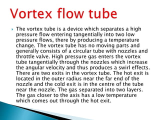
- 3. ï― The vortex tube is a device which separates a high pressure flow entering tangentially into two low pressure flows, there by producing a temperature change. The vortex tube has no moving parts and generally consists of a circular tube with nozzles and throttle valve. High pressure gas enters the vortex tube tangentially through the nozzles which increase the angular velocity and thus produces a swirl effects. There are two exits in the vortex tube. The hot exit is located in the outer radius near the far end of the nozzle and the cold exit is in the centre of the tube near the nozzle. The gas separated into two layers. The gas closer to the axis has a low temperature which comes out through the hot exit.
- 4. ï― There are two types of vortex tube: ï― 1. Uniform vortex tube ï― 2. Counter flow vortex tube
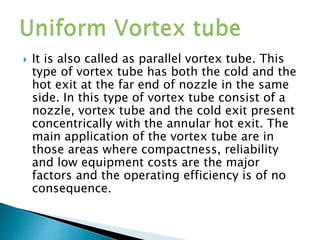
- 5. ï― It is also called as parallel vortex tube. This type of vortex tube has both the cold and the hot exit at the far end of nozzle in the same side. In this type of vortex tube consist of a nozzle, vortex tube and the cold exit present concentrically with the annular hot exit. The main application of the vortex tube are in those areas where compactness, reliability and low equipment costs are the major factors and the operating efficiency is of no consequence.
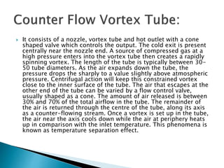
- 7. ï― It consists of a nozzle, vortex tube and hot outlet with a cone shaped valve which controls the output. The cold exit is present centrally near the nozzle end. A source of compressed gas at a high pressure enters into the vortex tube then creates a rapidly spinning vortex. The length of the tube is typically between 30- 50 tube diameters. As the air expands down the tube, the pressure drops the sharply to a value slightly above atmospheric pressure. Centrifugal action will keep this constrained vortex close to the inner surface of the tube. The air that escapes at the other end of the tube can be varied by a flow control valve, usually shaped as a cone. The amount of air released is between 30% and 70% of the total airflow in the tube. The remainder of the air is returned through the centre of the tube, along its axis as a counter-flowing stream. Once a vortex is set up in the tube, the air near the axis cools down while the air at periphery heats up in comparison with the inlet temperature. This phenomena is known as temperature separation effect.
- 9. ï― 1. Compressed air is passed through the nozzle in the tube and it expands and acquires high velocity due to particular shape of the nozzle. ï― 2. A vortex flow is created in the chamber and air travels in spiral like motion along the periphery of the hot side. This flow is restricted by the valve. ï― 3. When the pressure of the air near valve is made more than outside by partly closing the valve, a reserved axial flow through the core of the hot side starts from high- pressure region to low-pressure region. ï― 4. Inside the hot tube, both inner stream of air and outer stream of air rotates with same angular velocity. ï― 5. However, because of the principle of the conservation of angular momentum, the rotation of speed of the smaller vortex be expected to increase.
- 10. 6. But in the vortex tube the speed of the inner vortex remains same. Angular momentum has been lost from the inner vortex. 7. The energy that is lost from the inner vortex shows up as heat in the outer vortex. During this process, heat transfer takes place between reversed stream and forward stream. 8. Therefore, air stream through the core gets cooled below the inlet temperature of the air in the vortex tube, while air stream in the forward direction gets heated up. 9. The cold stream is escaped through the diaphragm hole into the cold side, while hot stream is passed through the opening of the valve. 10. By controlling the opening of the valve, the quantity of the cold air and its temperature can be varied.
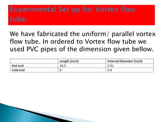
- 11. We have fabricated the uniform/ parallel vortex flow tube. In ordered to Vortex flow tube we used PVC pipes of the dimension given bellow.
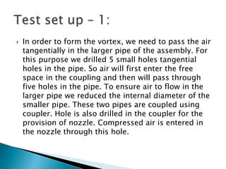
- 12. ï― In order to form the vortex, we need to pass the air tangentially in the larger pipe of the assembly. For this purpose we drilled 5 small holes tangential holes in the pipe. So air will first enter the free space in the coupling and then will pass through five holes in the pipe. To ensure air to flow in the larger pipe we reduced the internal diameter of the smaller pipe. These two pipes are coupled using coupler. Hole is also drilled in the coupler for the provision of nozzle. Compressed air is entered in the nozzle through this hole.
- 13. Figure 3: Nozzle for compressed air Figure 4: Reduced internal diameter of smaller pipe
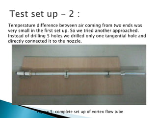
- 14. Temperature difference between air coming from two ends was very small in the first set up. So we tried another approached. Instead of drilling 5 holes we drilled only one tangential hole and directly connected it to the nozzle. Figure 5: complete set up of vortex flow tube
- 15. In order to block air at the other end of the large pipe (Hot end), we made a provision to have a movable valve. This helps in varying the area of outlet section of the tube. Figure 6: Movable Valve
- 16. ï― After injecting the air at the pressure of 6 bar, we found out the difference in the temperature of the air at both the ends (around 50C). ï― This temperature difference is not noticeable or not as expected from the vortex flow tube. As vortex flow tubes generally give the difference around 70-80 0 C.
- 17. ï― One reason for the failure of our set up is the air leakage. Some amount of air was leaking from the coupling of the pipes. ï― In order to form the vortex, air must enter the pipe tangentially. Our set up might not able to flow air tangentially in the pipe.
- 18. ï― It uses air as refrigerant, so there is no leakage problem. ï― There are no moving parts in the vortex tube ï― Vortex tube is simple in design and it avoids control system. ï― It is light in weight and requires less space. ï― Initial cost is low and its working expenses are also less, where compresses air is readily available. ï― Maintenance is simple and no skilled labours are required. ï― Very simple design can easily be made at home. ï― Can cool the fluid up to 40 0C.
- 19. ï― Its low COP ï― Limited capacity. ï― Small portion of the compressed air appearing as the cold air limits its wide use in practice.
- 20. ï― Vortex tubes are extremely small and as it produce hot as well as cold air. It may be used in industries where both are simultaneously required. ï― Low temperatures can be obtained without any difficulty, so it is very much useful in industries for spot cooling of electronic components. ï― It is commonly used for body cooling of the workers in mines.
- 21. Thank you