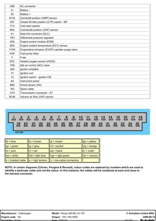
VW 9A engine wiring diagram
- 1. X88 AC connector 31 Battery - 30 Battery + B132 Camshaft position (CMP) sensor S57 Closed throttle position (CTP) switch - MT Y14 Cold start injector B54 Crankshaft position (CKP) sensor X1 Data link connector (DLC) Y63 Differential pressure regulator A35 Engine control module (ECM) B24 Engine coolant temperature (ECT) sensor Y104 Evaporative emission (EVAP) canister purge valve K20 Fuel pump relay F Fuse B72 Heated oxygen sensor (HO2S) Y99 Idle air control (IAC) valve A52 Ignition amplifier T1 Ignition coil 15 Ignition switch - ignition ON A5 Instrument panel B69 Knock sensor (KS) W3 Spare cable X79 Transmission connector - AT B148 Volume air flow (VAF) sensor bl = blue br = brown el = cream ge = yellow gn = green gr = grey nf = neutral og = orange rs = pink rt = red sw = black vi = violet ws = white hbl = light blue hgn = light green rbr = maroon x = braided cable y = high tension z = non-cable connection NOTE: In certain diagrams (Citroen, Peugeot & Renault), colour codes are replaced by numbers which are used to identify a particular cable and not the colour. In this instance, the cables will be numbered at each end close to the harness connector. Manufacturer: Volkswagen Model: Passat (88-96) 2,0 16V ? Autodata Limited 2004 Engine code: 9A Output: 100 (136) 5800 2009-09-12
- 2. Manufacturer: Volkswagen Model: Passat (88-96) 2,0 16V ? Autodata Limited 2004 Engine code: 9A Output: 100 (136) 5800 2009-09-12

