Water level indicator
- 3. ARSHAD ALI (10787) Department of Electrical Engineering NUML Islamabad.
- 4. ď‚–ď‚™This simple water level indicator will activate an active buzzer (e.g. BeStar BPT-23CX ) in order to make a noise when a certain level of water is being reached. Because the water sensor and the command circuit are located on the same printed circuit board, indicator, together with its 9 V battery and the buzzer can be mounted in a compact case. Obviously the sensor, that is made by corossion, on the board, must not be mounted directly on iron or steel bathtubs but with a magnet atached on the case. INTRODUCTION
- 7. List of COMPONENTS used in the circuit
- 8. IC NE 555 • The 555 integrated circuit acts as a counter. When activated by current entering in through pin 2, it starts to count for a certain amount of time. When it has finished counting it emits current from pin 3. This usually activates other components such as LEDs or relays
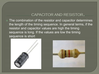
- 9. ď‚ž The combination of the resistor and capacitor determines the length of the timing sequence. In general terms, if the resistor and capacitor values are high the timing sequence is long. If the values are low the timing sequence is short
- 10. A buzzer or beeper is an audio signaling device, which may be mechanical, electromechanical, or piezoelectric. Typical uses of buzzers and beepers include alarm devices, timers and confirmation of user input such as a mouse click or keystroke The LED lights when current flows through it. In this circuit it indicates when pin three is emitting current. BUZZER AND LED
- 11. ď‚–ď‚™ Here is a simple water level alarm circuit using 555 timer that will produce an audible alarm when the water level reaches a preset level.The circuit can be powered of a 3V battery and is very handy to use. ď‚™ The circuit is based on an astable multivibrator wired around IC1 (NE 555).The operating frequency of the astable multivibrator here will depend on capacitor C1, resistances R1,R2 and the resistance across the probes A&B.When there is no water up to the probes,they will be open and so the multivibrator will not produce oscillations and the buzzer will not beep.When there is water up to the level of probes,some current will pass through the water,the circuit will be closed to some extend,and the IC will start producing oscillations in a frequency proportional to the value of C1,R1,R2 and the resistance of water across the probes.The buzzer will beep to indicate the presence of water up to the level of the sensing probes. DISCRIPTION
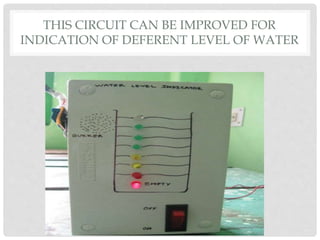
- 12. THIS CIRCUIT CAN BE IMPROVED FOR INDICATION OF DEFERENT LEVEL OF WATER
- 13. ď‚ž 1: Fuel level indicator in vehicles.
- 15. 3: AUTOMATIC WATER LEVEL CONTROLLER CAN BE USED IN HOTELS, FACTORIES, HOMES APARTMENTS, COMMERCIAL COMPLEXES, DRAINAGE, ETC., IT CAN BE FIXED FOR SINGLE PHASE MOTOR, SINGLE PHASE SUBMERSIBLES, THREE PHASE MOTORS. (FOR 3Æ AND SINGLE PHASE SUBMERSIBLE STARTER IS NECESSARY) AND OPEN WELL, BORE WELL AND SUMP. WE CAN CONTROL TWO MOTOR AND TWO SUMPS AND TWO OVERHEAD TANKS BY SINGLE UNIT.
- 16. 4:Liquid level indicator in the huge containers in the companies.


