


![Electricity meter
ŌĆó Electric meter or energy meter is a device that measures the amount of
electrical energy consumed. The most common unit of measurement
on the electricity measurement is the kilowatt hour [kWh], which is
equal to the amount of energy used by a load of one kilowatt hour over
a period of one hour.](https://image.slidesharecdn.com/instrumentationandautomationofpowerplant-230222093655-fac57dcb/85/Instrumentation-and-Automation-of-Power-Plant-pptx-15-320.jpg)


More Related Content
Similar to Instrumentation and Automation of Power Plant.pptx (20)
Recently uploaded (20)


Instrumentation and Automation of Power Plant.pptx
- 1. Instrumentation and Automation of Power Plant
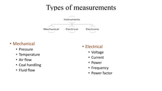
- 3. Types of measurements ŌĆó Mechanical ŌĆó Pressure ŌĆó Temperature ŌĆó Air flow ŌĆó Coal handling ŌĆó Fluid flow ŌĆó Electrical ŌĆó Voltage ŌĆó Current ŌĆó Power ŌĆó Frequency ŌĆó Power factor
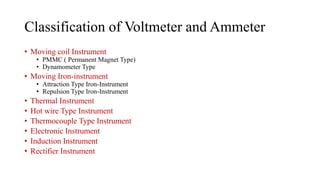
- 5. ŌĆó Moving coil Instrument ŌĆó PMMC ( Permanent Magnet Type) ŌĆó Dynamometer Type ŌĆó Moving Iron-instrument ŌĆó Attraction Type Iron-Instrument ŌĆó Repulsion Type Iron-Instrument ŌĆó Thermal Instrument ŌĆó Hot wire Type Instrument ŌĆó Thermocouple Type Instrument ŌĆó Electronic Instrument ŌĆó Induction Instrument ŌĆó Rectifier Instrument Classification of Voltmeter and Ammeter
- 6. Permanent Magnet Moving Coil (PMMC)
- 7. PMMC ŌĆó when the moving coil instrument is connected in the circuit, operating current flows through the coil. ŌĆó This current carrying coil is placed in the magnetic field produced by the permanent magnet and therefore, mechanical force acts on the coil. ŌĆó As the coil attached to the moving system, the pointer moves over the scale. It may be noted here that if current direction is reversed the torque will also be reversed since the direction of the field of permanent magnet is same. ŌĆó Hence, the pointer will move in the opposite direction, i.e it will go on the wrong side of zero. ŌĆó In other words, these instruments work only when current in the circuit is passed in a definite direction i.e. for d.c only. ŌĆó So it is called permanent magnet moving coil instruments because a coil moves in the field of a permanent magnet.
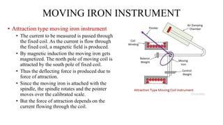
- 8. MOVING IRON INSTRUMENT ŌĆó Attraction type moving iron instrument ŌĆó The current to be measured is passed through the fixed coil. As the current is flow through the fixed coil, a magnetic field is produced. ŌĆó By magnetic induction the moving iron gets magnetized. The north pole of moving coil is attracted by the south pole of fixed coil. ŌĆó Thus the deflecting force is produced due to force of attraction. ŌĆó Since the moving iron is attached with the spindle, the spindle rotates and the pointer moves over the calibrated scale. ŌĆó But the force of attraction depends on the current flowing through the coil.
- 9. ŌĆó Repulsion type moving iron instrument ŌĆó The basic principle behind the working of repulsion motor is that ŌĆ£similar poles repel each other.ŌĆØ ŌĆó This means two North poles will repel each other. Similarly, two South poles will repel each other. ŌĆó When the repulsion motor winding is supplied with single-phase AC, it produces a magnetic flux along the direct axis
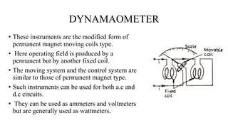
- 10. DYNAMAOMETER ŌĆó These instruments are the modified form of permanent magnet moving coils type. ŌĆó Here operating field is produced by a permanent but by another fixed coil. ŌĆó The moving system and the control system are similar to those of permanent magnet type. ŌĆó Such instruments can be used for both a.c and d.c circuits. ŌĆó They can be used as ammeters and voltmeters but are generally used as wattmeters.
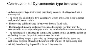
- 11. Construction of Dynamometer type instruments ŌĆó A dynamometer type instrument essentially consists of a fixed coil and a moving coil. ŌĆó The fixed coil is split into two equal parts which are placed close together and parallel to each other. ŌĆó The moving coil is pivoted in between the two fixed coils. ŌĆó The fixed and moving coils may be excited separately or they may be connected in series depending upon the use to which the measurement is put. ŌĆó The moving coil is attached to the moving system so that under the action of deflecting torque, the pointer moves over the scale. ŌĆó The controlling torque is provided by two springs which also serve the additional purpose of leading the current into and out of the moving coil. ŌĆó Air friction damping is provided in such instruments.
- 12. Working of Dynamometer type instruments: ŌĆó When instrument is connected in the circuit, operating currents flow through the coils. ŌĆó Due to this, mechanical force exists between the coils. The result is that the moving coil moves the pointer over the scale. ŌĆó The pointer comes to rest at a position where deflecting torque is equal to the controlling torque.by reversing the current, the field due to fixed coils is reversed as well as the current in the moving coil, so that the direction of deflecting torque remains unchanged. ŌĆó Therefore, such instruments can be used for both d.c and a.c measurements.
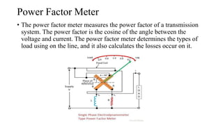
- 13. Power Factor Meter ŌĆó The power factor meter measures the power factor of a transmission system. The power factor is the cosine of the angle between the voltage and current. The power factor meter determines the types of load using on the line, and it also calculates the losses occur on it.
- 14. Power Factor Meter Working Principle ŌĆó The basic working principle of power factor meter is similar to that of dynamometer type wattmeter i.e. when the field produced by moving system tries to come in line with the field produced by the fixed coil, deflecting torque is exerted on the moving system which deflects the pointer attached to it (the moving system)
- 15. Electricity meter ŌĆó Electric meter or energy meter is a device that measures the amount of electrical energy consumed. The most common unit of measurement on the electricity measurement is the kilowatt hour [kWh], which is equal to the amount of energy used by a load of one kilowatt hour over a period of one hour.
- 16. Construction of Energy Meter ŌĆó Driving system ŌĆó It consists of a series magnet and a shunt magnet. The coil of the series magnet is excited by load current while that of the shunt magnet is excited by a current proportional to the supply voltage. These two coils are respectively referred as current coil and potential coil (or pressure coil) of the energy meter. ŌĆó Moving system ŌĆó It consists of a freely suspended, light aluminum disc mounted on an alloy shaft and placed amidst the air-gap of the two electromagnets.
- 17. ŌĆó Braking system ŌĆó It consists of a position-adjustable permanent magnet placed near one edge of the disc. When the disc rotates in the gap between the two poles of the brake magnet, eddy currents are set up in the disc. These currents react with the brake magnet field and provide the required braking torque damping out the disc motion if any, beyond the required speed.. The braking torque can be adjusted as required by varying the position of the braking magnet. ŌĆó Recording system ŌĆó It is a mechanism used to record continuously a number which is proportional to the revolutions made by the disc. Thus it is the counter part of the pointer and scale of indicating instruments. The shaft that supports the disc is connected by a gear arrangement to a clock mechanism on the front of the meter. It is provided with a decimally calibrated read out of the total energy consumption in KWh.
- 18. Digital Frequency Meter ŌĆó A digital frequency meter is an electronic instrument that can measure even the smaller value of frequency up to 3 decimals of a sinusoidal wave and displays it on the counter display. It counts the frequency periodically and can measure in the range of frequencies between 104 to 109 hertz. The entire concept is based on the conversion of sinusoidal voltage into continuous pulses ( 01, 1.0, 10 seconds) along a single direction.
- 19. Construction of Digital Frequency Meter
- 20. ŌĆó The main components of digital frequency meter are ŌĆó Unknown Frequency Source: It is used to measure the unknown value of input signal frequency. ŌĆó Amplifier: It amplifies low-level signals to high-level signals. ŌĆó Schmitt Trigger: The main purpose of the Schmitt trigger is to convert the analog signal into a digital signal in a pulse train form. It is also known as ADC and basically acts as a comparator circuit. ŌĆó And Gate: The generated output from AND gate is obtained only when the inputs exist at the gate. One of the terminals of the AND gate is connected to Schmitt Trigger output, and another terminal is connected to a flipflop. ŌĆó Counter: It operates based on the clock period, which starts from ŌĆ£0ŌĆØ. One input is taken from the output of the AND gate. The counter is constructed by cascading many flip flops. ŌĆó Crystal Oscillator: When a DC supply is given to a crystal oscillator (frequency of 1MHz) it generates a sinusoidal wave. ŌĆó Time-Based Selector: Depending on reference the time period of signals can be varied. It consists of a clock oscillator which gives an accurate value. The clock oscillator output is given as input to Schmitt trigger which converts sinusoidal wave into a series of a square wave of the same frequency. These continuous pulses are sent to frequency divider decade which is in series that are connected one after the another, where each divider decade consists of a counter decade and the frequency is divided by 10. Each decade frequency divider provides respective output using a selector switch. ŌĆó Flip Flop: It provides output based on input.
- 21. Working Principle ŌĆó When an unknown frequency signal is applied to the meter it passes on to amplifier which amplifies the weak signal. ŌĆó Now the amplified signal is now applied to Schmitt trigger which can convert input sinusoidal signal into a square wave. ŌĆó The oscillator also generates sinusoidal waves at periodic intervals of time, which is fed to Schmitt trigger. ŌĆó This trigger converts sin wave into a square wave, which is in the form of continuous pulses, where one pulse is equal to one positive and one negative value of a single signal cycle. ŌĆó The first pulse which is generated is given as input to the gate control flip flop turning ON AND gate. ŌĆó The output from this AND gate count decimal value. ŌĆó Similarly, when the second pulse arrives, it disconnects AND gate, and when the third pulse arrives the AND gate turns ON and the corresponding continuous pulses for a precise time interval which is the decimal value is displayed on the counter display.
- 22. Non electrical parameters ŌĆó Flow of feed water, fuel, air and steam with correction factor for temperature ŌĆó Steam pressure and steam temperature ŌĆó Drum level measurement ŌĆó Radiation detector ŌĆó Smoke density measurement ŌĆó Dust monitor.
- 23. MEASUREMENT OF AIR FLOW