
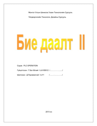
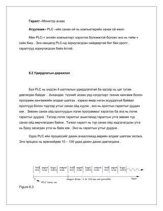
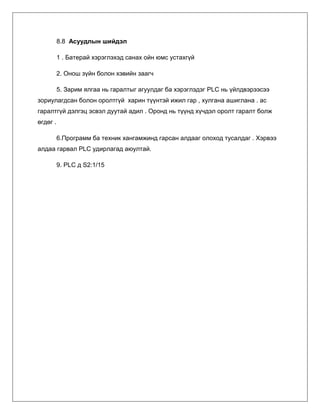
![Flicker –Гэрэл анивчуулах C-3 lab
Let’s make the outputs flicker by using two timers to control ON time and
OFF time .
–ë“Ø–≥–¥—ç—ç—Ä—ç—ç ON –±–∞ OFF –≥—ç—Å—ç–Ω 2 —Ç–æ—Ö–∏—Ä—É—É–ª–∞–≥—á–∏–π–≥ –∞—à–∏–≥–ª–∞–Ω
–≥—ç—Ä—ç–ª –∞–Ω–∏–≤—á—É—É–ª–∞—Ö –¥–∞—Å–≥–∞–ª —Ö–∏–π—Ü–≥—ç—ç–µ .
Caution – Анхааруулга
Click the ladder program area to enable operation. The title bar will turn blue .
Ladder дээр дарж програмын удирдлагыг идэвхжүүлнэ.
Дөрвөлжин цэнхэр хүснэгт идэвхжинэ.
Key operations are not enabled when the title and items are grayed out .
1. Click [Edit Ladder] button on the remote control .
Edit Ladder- —ã–≥ –¥–∞—Ä—Å–Ω–∞–∞—Ä —É–¥–∏—Ä–ª–∞–≥–∞—Ç–∞–π —Ö–æ–ª–±–æ–≥–¥–æ–Ω–æ.
2. Input the program below - Өгөгдлийг оруулах
Place the cursor inside the ladder diagram on the left hand side begin to input
data.
Диаграмын зүүн гар талд буюу хулганы суман дахь
дөрвөлжин дотроос өгөдлийг оруулж эхэлнэ.
These symbols can be input by pressing the following keys .
Эдгээр тэмдэгтүүдийг дээр хэлсний дагуу оруулна .
In the “Enter symbol ”dialogbox, enter T3 K20 or T4 K40 and click [OK] when
writing the timer setting (Use a space between T3 and K20 )](https://image.slidesharecdn.com/12-131229191913-phpapp01/85/1-2-11-320.jpg)
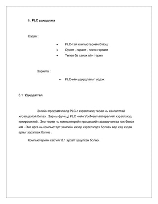
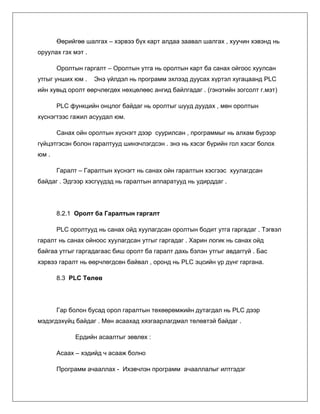
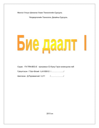
![–¢—ç–º–¥—ç–≥—Ç –æ—Ä—É—É–ª–∞—Ö—ã–≥ –¥–∞—Ä—Å–Ω–∞–∞—Ä –≥–∞—Ä—á –∏—Ä—ç—Ö —Ö–∞—Ä–∏–ª—Ü–∞
—Ü–æ–Ω—Ö–Ω–æ–æ—Å T3 K20 –±–æ–ª–æ–Ω T4 K40 —Ç–æ—Ö–∏—Ä—É—É–ª—Å–∞–Ω–∞–∞—Ä –æ—Ä—É—É–ª–∞—Ö
–±–æ–ª–Ω–æ .
3. Press the [F4] key to convert the program you have input .
F4 товчлуурыг дарж програмын оролтыг хувиргаж өгдөг.
4. Write the program to the PLC by selecting “Online”- Write to PLC “ in the
ladder program area.
Write to PLC нь бичсэн програмыг хөрвүүлнэ .
Chapter 2
Confirm Flicker Operation
1. Turn ON (SW1)[X24] on the operation panel .
Switch 1 – ээр X24 г тохируулан асаах
2. After 2 seconds (timed by T3), the signal Green (Y1) is lit .
2 —Å–µ–∫—É–Ω–¥—ã–Ω –¥–∞—Ä–∞–∞ (T3 –∞–∞—Ä —Ç–æ—Ö–∏—Ä—É—É–ª–∞—Ö)Y1 –±—É—é—É –Ω–æ–≥–æ–æ–Ω
дохио өгөх
3. The signal Green (Y1) remains lit for 4 seconnds (timed by T4)
–ù–æ–≥–æ–æ–Ω –¥–æ—Ö–∏–æ –Ω—å 4 —Å–µ–∫—É–Ω–¥—ã–Ω —Ç—É—Ä—à –¥–æ—Ö–∏–æ ”©–≥–Ω”©. (T4—ç—ç—Ä
—Ç–æ—Ö–∏—Ä—É—É–ª–Ω–∞ )
4. Subsequently , Green (Y1) will flicker OFF for 2 seconds and ON for $
second
–î–∞—Ä–∞–∞ –Ω—å –Ω–æ–≥–æ–æ–Ω –¥–æ—Ö–∏–æ –Ω—å 2 —Å–µ–∫—É–Ω–¥—ã–Ω —Ç—É—Ä—à —É–Ω—Ç–∞—Ä—á 4
—Å–µ–¥—É–Ω–¥—ã–Ω —Ç—É—Ä—à –∞—Å–∞–∂ –∞–Ω–∏–≤—á–∏–Ω–∞ .](https://image.slidesharecdn.com/12-131229191913-phpapp01/85/1-2-12-320.jpg)


![[EN] PLC Checker Datasheet](https://cdn.slidesharecdn.com/ss_thumbnails/plc-checkeren-150417111939-conversion-gate02-thumbnail.jpg?width=560&fit=bounds)

More Related Content
What's hot (20)
Viewers also liked (15)


Similar to –±–∏–µ –¥–∞–∞–ª—Ç 1,2 –±–∞—Ç ”©–ª–∑–∏–π (20)


More from Enhmandah Hemeelee (20)


–±–∏–µ –¥–∞–∞–ª—Ç 1,2 –±–∞—Ç ”©–ª–∑–∏–π
- 1. Монгол Улсын Шинжлэх Ухаан Технологийн Сургууль Үйлдвэрлэлийн Технологи, Дизайны Сургууль Сэдэв : PLC OPERATION Гүйцэтгэсэн : Г.Бат-Өлзий I.LA10D012 /………………..../ Шалгасан : Д.Пүрэвмагнай I.LI11 /…………………./ 2013 он
- 2. 8 . PLC удирдлага Сэдэв : PLC-тэй компьютерийн бүтэц Оролт , гаралт , логик гаргалт Төлөв ба санах ойн төрөл Зорилго : PLC-ийн удирдлагыг мэдэх 8.1 Удирдатгал Энгийн програмчлалд PLC-г хэрэглэхэд төрөл нь хангалттай хүрэлцээтэй билээ . Зарим функцд PLC –ийн VonNeumanтөрөлийг хэрэглэхэд тохиромжтой . Энэ төрөл нь компьютерийн процессийн зааварчилгаа гэж болох юм . Энэ арга нь компьютерт хамгийн ихээр хэрэглэгдэх боловч өөр хэд хэдэн аргыг хэрэглэж болно . Компьютерийн хэсгийг 8.1 зурагт үзүүлсэн болно .
- 3. Зураг 8.1 Хувийн компьютерийн хялбарчилсан бүтэц Оролт нь гар болон хулганаас хүлээн авч , гаралт нь дэлгэцэнд илгээн мөн диск болон санах ой 2 нь 2лаа оролт болон гаралтанд агуулагдана.(Тэмдэглэл :Эдгээр зааварууд нь инженерүүдэд маш чухал багаад хаана ч гэсэн анхаарал зүйл мөн )
- 4. Зураг 8.2 Оролт гаралтын бүтэц Энэ зурагт үзүүлсэнээр зүүн талаас өгөгдөл оруулах үндсэн оролтууд . (Тэмд: инженерийн схемд зүүн талаас оролтууд баруун талаас гаралтууд байрлана) Энэ схемийн эхэнд СPU буюу төв санах ойг оруулах шаардлагатай. CPU ийн үндсэн өгөгдөл нь бусад схемийн хувьд гаралт болдог байна . Бидний мэдэж байгаагаар хувийн компьютерыг түүн шиг тохируулвал гаралт нь дэлгэц болж , оролтын хариу үйлдэл нь гар болон хулганаас дуудагдана. Мөн PLC нь компьютерын процессийг тохируулдаг . Тэгвэл компьютерийн хэрэглээнд нь бүхэлдээ ижил төстэй . Оролтууд -гар ба унтраалга ижил төстэй Оролтын схем – Компьютер – 686 CPU нь PLC CPUийн хэсэгтэй адил Гаралтын схем–
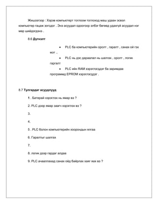
- 5. Гаралт –Монитор асаах Агууламж– PLC –ийн санах ой нь компьютерийн санах ой ижил Мөн PLC–г энгийн компьютерт хэрэглэх боломжтой боловч энэ нь тийм ч сайн биш . Энэ нөхцөлд PLC-нд зориулагдсан найдвартай бат бөх оролт , гаралтууд зориулагдсан байх ѐстой . 8.2 Удирдлагын дараалал Бүх PLC нь үндсэн 4 шатлалын удирдлагатай ба эдгээр нь цаг тутам давтагдан байдаг . Анхандаа түүнийг асаах үед нэгдүгээрт техник хангамж болон программ хангамжийн алдааг шалгах . хэрвээ ямар нэгэн асуудалгүй байвал оролтууд болон тэдгээр утгыг санах ойд хуулж , энэ нь оролтын гаралтыг дуудах юм . Зөвхөн санах ойд оролтуудын логик программыг хэрэглэх ба энэ нь логик гаралтыг дуудна . Тэгээд логик гаралтыг ашиглахад гаралтын утга зөвхөн түр санах ойд өөрчлөгдсөн байна . Тэгвэл гаралт нь түр санах ойд хадгалагдсан утга нь буюу засагдан утга нь байх юм . Энэ нь гаралтын утгыг дуудна . Одоо PLC ийн процессийг дахин ачааллахад өөрийн алдааг шалгаж эхлэнэ. Энэ процесс нь ерөнхийдөө 10 – 100 удаа дахин дахин давтагдана . Figure 8.3
- 6. Өөрийгөө шалгах – хэрвээ бүх карт алдаа заавал шалгах , хуучин хэвэнд нь оруулах гэх мэт . Оролтын гаргалт – Оролтын утга нь оролтын карт ба санах ойгоос хуулсан утгыг унших юм . Энэ үйлдэл нь программ эхлээд дуусах хүртэл хугацаанд PLC ийн хувьд оролт өөрчлөгдөх нөхцөлөөс ангид байлгадаг . (гэнэтийн зогсолт г.мэт) PLC функцийн онцлог байдаг нь оролтыг шууд дуудах , мөн оролтын хүснэгтээс гажил асуудал юм. Санах ойн оролтын хүснэгт дээр суурилсан , программыг нь алхам бүрээр гүйцэтгэсэн болон гаралтууд шинэчлэгдсэн . энэ нь хэсэг бүрийн гол хэсэг болох юм . Гаралт – Гаралтын хүснэгт нь санах ойн гаралтын хэсгээс хуулагдсан байдаг . Эдгээр хэсгүүдэд нь гаралтын аппаратууд нь удирддаг . 8.2.1 Оролт ба Гаралтын гаргалт PLC оролтууд нь санах ойд хуулагдсан оролтын бодит утга гаргадаг . Тэгвэл гаралт нь санах ойноос хуулагдсан утгыг гаргадаг . Харин логик нь санах ойд байгаа утгыг гаргадагаас биш оролт ба гаралт дахь бэлэн утгыг авдаггүй . Бас хэрвээ гаралт нь өөрчлөгдсөн байвал , оронд нь PLC эцсийн үр дүнг гаргана. 8.3 PLC Төлөв Гар болон бусад орол гаралтын төхөөрөмжийн дутагдал нь PLC дээр мэдэгдэхүйц байдаг . Мөн асаахад хязгаарлагдмал төлөвтэй байдаг . Ердийн асаалтыг зөвлөх : Асаах – хэдийд ч асааж болно Программ ачааллах - Ихэвчлэн программ ачааллалыг илтгэдэг
- 7. Алдаанууд – PLC ний программ болон техник хангамжийн асуудлыг илтгэдэг . Эдгээр нь ердийн алдаануудийг засахад хэрэглэгддэг. Мөн PLC техник хангамжинд хязгаарлагдмал байдаг . Хамгийн хэвийн программ ажиллахын тулд унтраалга засварлагддаг. Энэ унтраалга нь зөвшөөрөлгүй программыг зогсоох , өөрчлөх зэргээс сэргийлэх үүднээс ашиглагдана. PLC бараг хэзээ ч асааж унтраасан өмнөх хэлбэртээ байдаггүй .PLC төлөв логикоор илэрдэг . Энэ нь программийг хэвийн байгаа эсэхийг шалгах үүрэг гүйцэтгэдэг . 8.4 Санах ойн төрлүүд Өнөөдөр бид компьютерийн санах ойн төрлөөс хэдхээнийг л хэрэглэдэг . RAM (Random Access Memory ) – Энэ нь маш хурдан санах ой боловч компьютер ундрах үед хийж байсан зүйлс бүгд устдаг . Яг л богино настай санах ой гэсэн үг . ROM(Read Only Memory ) – Энэ санах ой нь тогтмол ба устгаж чаддаггүй санах ой юм . Энэ нь ихэвчлэн үйлдлийн системд хэрэглэгддэг . EPROM (Erasable Programmable Read Only Memory ) - ROM тай яг ижил зарчмаар ажилладаг боловч асаах үед болон программыг дахин ачааллах үед устлаг байна . EEPROM(Electronically Erasable Programmable Read Only Memory )– ROMтайбас ижил боловч EPROM бодвол түгээмэл хэрэглэгддэг . Компьютерийг унтраах үед RAM дахь юмнууд устддаг ба хэрэв батерай хэрэглэвэл устахгүй байж ч болох юм. 8.5 Энгийн PLC –ийн программ хангамж
- 8. Жишээгээр : Хэрэв компьютерт тоглоом тоглоход маш удаан эсвэл компьютер гацаж зогсдог . Энэ асуудал одоогоор элбэг бөгөөд удахгүй асуудал нэг мөр шийдэгдэнэ . 8.6 Дүгнэлт PLC ба компьютерийн оролт , гаралт , санах ой гэх мэт .. PLC нь дэс дараалал нь шалгах , оролт , логик гаргалт PLC ийн RAM хэрэглэгддэг ба заримдаа программд EPROM хэрэглэгддэг . 8.7 Тулгардаг асуудлууд 1 . Батерай хэрэглэх нь ямар вэ ? 2. PLC дээр ямар заагч хэрэглэх вэ ? 3. 4. 5 . PLC болон компьютерийн хоорондын ялгаа 6. Гаралтыг шалгах 7. 8. логик дээр гардаг алдаа 9. PLC ачааллахад санах ойд байрлах хаяг яах вэ ?
- 9. 8.8 Асуудлын шийдэл 1 . Батерай хэрэглэхэд санах ойн юмс устахгүй 2. Онош зүйн болон хэвийн заагч 5. Зарим ялгаа нь гаралтыг агуулдаг ба хэрэглэдэг PLC нь үйлдвэрээсээ зориулагдсан болон оролтгүй харин түүнтэй ижил гар , хулгана ашиглана . ас гаралтгүй дэлгэц эсвэл дуутай адил . Оронд нь түүнд хүчдэл оролт гаралт болж өгдөг . 6.Программ ба техник хангамжинд гарсан алдааг олоход тусалдаг . Хэрвээ алдаа гарвал PLC удирлагад аюултай. 9. PLC д S2:1/15
- 10. Монгол Улсын Шинжлэх Ухаан Технологийн Сургууль Үйлдвэрлэлийн Технологи, Дизайны Сургууль Сэдэв : FX-TRN-BEG-E програмын С3 буюу Гэрэл анивчуулах лаб Гүйцэтгэсэн : Г.Бат-Өлзий I.LA10D012 /………………..../ Шалгасан : Д.Пүрэвмагнай I.LI11 /…………………./ 2013 он
- 11. Flicker –Гэрэл анивчуулах C-3 lab Let’s make the outputs flicker by using two timers to control ON time and OFF time . Бүгдээрээ ON ба OFF гэсэн 2 тохируулагчийг ашиглан гэрэл анивчуулах дасгал хийцгээе . Caution – Анхааруулга Click the ladder program area to enable operation. The title bar will turn blue . Ladder дээр дарж програмын удирдлагыг идэвхжүүлнэ. Дөрвөлжин цэнхэр хүснэгт идэвхжинэ. Key operations are not enabled when the title and items are grayed out . 1. Click [Edit Ladder] button on the remote control . Edit Ladder- ыг дарснаар удирлагатай холбогдоно. 2. Input the program below - Өгөгдлийг оруулах Place the cursor inside the ladder diagram on the left hand side begin to input data. Диаграмын зүүн гар талд буюу хулганы суман дахь дөрвөлжин дотроос өгөдлийг оруулж эхэлнэ. These symbols can be input by pressing the following keys . Эдгээр тэмдэгтүүдийг дээр хэлсний дагуу оруулна . In the “Enter symbol ”dialogbox, enter T3 K20 or T4 K40 and click [OK] when writing the timer setting (Use a space between T3 and K20 )
- 12. Тэмдэгт оруулахыг дарснаар гарч ирэх харилца цонхноос T3 K20 болон T4 K40 тохируулсанаар оруулах болно . 3. Press the [F4] key to convert the program you have input . F4 товчлуурыг дарж програмын оролтыг хувиргаж өгдөг. 4. Write the program to the PLC by selecting “Online”- Write to PLC “ in the ladder program area. Write to PLC нь бичсэн програмыг хөрвүүлнэ . Chapter 2 Confirm Flicker Operation 1. Turn ON (SW1)[X24] on the operation panel . Switch 1 – ээр X24 г тохируулан асаах 2. After 2 seconds (timed by T3), the signal Green (Y1) is lit . 2 секундын дараа (T3 аар тохируулах)Y1 буюу ногоон дохио өгөх 3. The signal Green (Y1) remains lit for 4 seconnds (timed by T4) Ногоон дохио нь 4 секундын турш дохио өгнө. (T4ээр тохируулна ) 4. Subsequently , Green (Y1) will flicker OFF for 2 seconds and ON for $ second Дараа нь ногоон дохио нь 2 секундын турш унтарч 4 седундын турш асаж анивчина .