![Source Basics Copyright
2000
Modulation
...Where the information resides
AM, Pulse
FM PM
q
V= A(t) sin[ (t)]
p
V= A(t) sin[2 f(t) + (t)]
f](https://image.slidesharecdn.com/130310124026signalgeneratorsourcebasics-230930230130-cc332b43/85/130310124026_Signal-Generator-Source-Basics-ppt-30-320.jpg)
![Source Basics Copyright
2000
Modulation: Analog
Frequency Modulation
Voltage
Time
Important Signal Generator Specs
for Frequency Modulation
V= A sin[2 f t + m(t)]
p c b
F /F
dev mod
b = D
’ü¼ Frequency Deviation
’ü¼ Modulation Frequency
’ü¼ dcFM
’ü¼ Accuracy
’ü¼ Resolution](https://image.slidesharecdn.com/130310124026signalgeneratorsourcebasics-230930230130-cc332b43/85/130310124026_Signal-Generator-Source-Basics-ppt-32-320.jpg)
![Source Basics Copyright
2000
Modulation: Analog
Phase Modulation
b = Df peak
V= A sin[2 p f t + m(t)]
Important Signal Generator Specs
for Phase Modulation
’ü¼ Phase deviation
’ü¼ Rates
’ü¼ Accuracy
’ü¼ Resolution
Voltage
Time
c b](https://image.slidesharecdn.com/130310124026signalgeneratorsourcebasics-230930230130-cc332b43/85/130310124026_Signal-Generator-Source-Basics-ppt-33-320.jpg)
![Source Basics Copyright
2000
Digital Modulation
...Binary Phase Shift Keying (BPSK)
f
V= A sin[2 ft + (t)]
(t) =
f1
f2
p f](https://image.slidesharecdn.com/130310124026signalgeneratorsourcebasics-230930230130-cc332b43/85/130310124026_Signal-Generator-Source-Basics-ppt-38-320.jpg)
![Source Basics Copyright
2000
Digital Modulation
...Quadrature Phase Shift Keying (QPSK)
V= A sin[2 ft + (t)]
f(t) =
f1 = 3 /4
p
f2 = /4
p
f3 = - /4
p
f4 = - 3
/4
p
p f](https://image.slidesharecdn.com/130310124026signalgeneratorsourcebasics-230930230130-cc332b43/85/130310124026_Signal-Generator-Source-Basics-ppt-40-320.jpg)

130310124026_Signal Generator (Source) Basics.ppt
- 1. Source Basics Copyright 2000 Agenda ’ü¼ Types of sources ’ü¼ CW ’ü¼ Swept ’ü¼ Signal Generator ’ü¼ Block Diagrams ’ü¼ Applications ’ü¼ Specifications
- 2. Source Basics Copyright 2000 Sources Generate Sine Waves Voltage Time Voltage Frequency This is the ideal output: most specs deal with deviations from the ideal and adding modulation to a sine wave RF Microwave Millimeter 20-50 GHz 300 GHz 3-6 GHz Spectrum Analyzer Oscilloscope
- 3. Source Basics Copyright 2000 Types of Sources ’ü¼ CW ŌĆō generates a single frequency, fixed sine wave ’ü¼ Swept ŌĆō sweeps over a range of frequencies ŌĆō may be phase continuous ’ü¼ Signal Generator ŌĆō adds modulation ŌĆō produces ŌĆ£real worldŌĆØ signal
- 4. Source Basics Copyright 2000 Agenda ’ü¼ Types of sources ’ü¼ CW ’ü¼ Swept ’ü¼ Signal Generator ’ü¼ Block Diagrams ’ü¼ Applications ’ü¼ Specifications
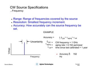
- 5. Source Basics Copyright 2000 CW Source Specifications ...Frequency Voltage Frequency Uncertainty ’ü¼ Range: Range of frequencies covered by the source ’ü¼ Resolution: Smallest frequency increment. ’ü¼ Accuracy: How accurately can the source frequency be set. EXAMPLE Accuracy = = CW frequency = 1 GHz = aging rate = 0.152 ppm/year = time since last calibrated = 1 year ’āÖ + _ fCW taging cal t * * fCW taging cal t Accuracy = 152 Hz + _
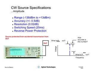
- 6. Source Basics Copyright 2000 CW Source Specifications ...Amplitude DUT Source protected from accidental transmission from DUT Voltage Frequency How accurate is this number? What is P out? What is P out? max min ’ü¼ Range (-136dBm to +13dBm) ’ü¼ Accuracy (+/- 0.5dB) ’ü¼ Resolution (0.02dB) ’ü¼ Switching Speed (25ms) ’ü¼ Reverse Power Protection
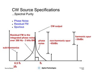
- 7. Source Basics Copyright 2000 ’ü¼ Phase Noise ’ü¼ Residual FM ’ü¼ Spurious CW Source Specifications ...Spectral Purity non-harmonic spur ~65dBc harmonic spur ~30dBc CW output Residual FM is the integrated phase noise over 300 Hz - 3 kHz BW phase noise 0.5 f0 f0 2f0 sub-harmonics
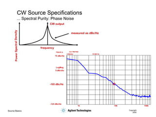
- 8. Source Basics Copyright 2000 CW Source Specifications ... Spectral Purity: Phase Noise CW output frequency measured as dBc/Hz Ch1 PM PSD 1k 10k 100k TRACE A: A Marker 10 000 Hz 75 dBc/Hz -125 dBc/Hz LogMag 5 dBc/div -105 dBc/Hz
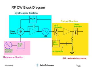
- 9. Source Basics Copyright 2000 RF CW Block Diagram Reference Oscillator VCO Phase Detector Frac-N divide by X ALC Modulator ALC Driver ALC Detector Output Attenuator ALC = automatic level control Reference Section Synthesizer Section Output Section
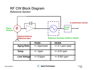
- 10. Source Basics Copyright 2000 RF CW Block Diagram Reference Section Phase Detector Optional External Reference Input Reference Oscillator (TCXO or OCXO) TCXO OCXO Aging Rate +/- 2ppm/year +/- 0.1 ppm /year Temp. +/- 1ppm +/- 0.01 ppm Line Voltage +/- 0.5ppm +/- 0.001 ppm to synthesizer section divide by X
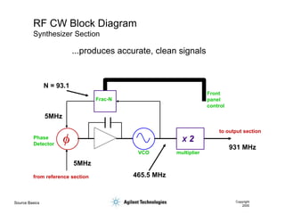
- 11. Source Basics Copyright 2000 RF CW Block Diagram Synthesizer Section VCO Phase Detector Frac-N from reference section to output section X 2 multiplier Front panel control 5MHz 465.5 MHz N = 93.1 931 MHz 5MHz ...produces accurate, clean signals
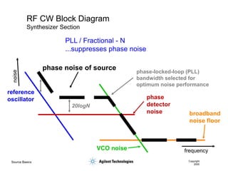
- 12. Source Basics Copyright 2000 RF CW Block Diagram Synthesizer Section reference oscillator phase noise of source VCO noise phase detector noise broadband noise floor 20logN phase-locked-loop (PLL) bandwidth selected for optimum noise performance PLL / Fractional - N ...suppresses phase noise frequency
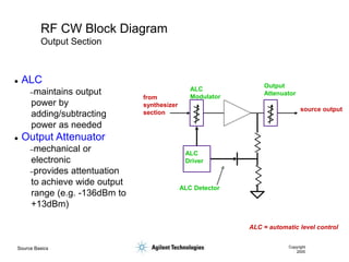
- 13. Source Basics Copyright 2000 RF CW Block Diagram Output Section ALC = automatic level control ALC Modulator ALC Driver ALC Detector Output Attenuator from synthesizer section source output ’ü¼ ALC ŌĆōmaintains output power by adding/subtracting power as needed ’ü¼ Output Attenuator ŌĆōmechanical or electronic ŌĆōprovides attentuation to achieve wide output range (e.g. -136dBm to +13dBm)
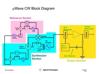
- 14. Source Basics Copyright 2000 mWave CW Block Diagram ALC Detector ALC Modulator ALC Driver Output Attenuator Sampler Reference Section Synthesizer Section Output Section Ref Osc VCO Phase Det Frac N by X VCO Phase Detector Frac-N Phase Detector Tuning Coils YIG Oscillator
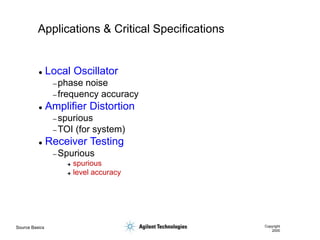
- 15. Source Basics Copyright 2000 Applications & Critical Specifications ’ü¼ Local Oscillator ŌĆō phase noise ŌĆō frequency accuracy ’ü¼ Amplifier Distortion ŌĆō spurious ŌĆō TOI (for system) ’ü¼ Receiver Testing ŌĆō Spurious ’ā© spurious ’ā© level accuracy
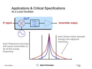
- 16. Source Basics Copyright 2000 Applications & Critical Specifications As a Local Oscillator IF signal transmitter output poor phase noise spreads energy into adjacent channels poor frequency accuracy will cause transmitter to be at the wrong frequency DUT
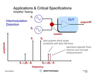
- 17. Source Basics Copyright 2000 Applications & Critical Specifications Amplifier Testing f2 f1 fU = 2f2 - f1 fL = 2f1 - f2 spurious signals from source can corrupt measurement frequency test system third order products will also fall here output RF isolator f1 f2 DUT Intermodulation Distortion
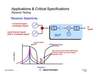
- 18. Source Basics Copyright 2000 Applications & Critical Specifications Receiver Testing IF Rejection Curve Frequency Level (dBm) spur from source and/or high levels of phase noise can cause a good receiver to fail source output IF signal in-channel signal (modulated signal) out-of-channel signal (CW or modulated signal) DUT Receiver Selectivity
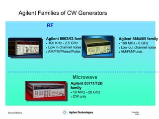
- 19. Source Basics Copyright 2000 Agilent Families of CW Generators RF Microwave Agilent 8664/65 family ’ü¼ 100 MHz - 6 GHz ’ü¼ Low out channel noise ’ü¼ AM/FM/Pulse. Agilent 8662/63 family ’ü¼ 100 KHz - 2.5 GHz ’ü¼ Low in channel noise ’ü¼ AM/FM/Phase/Pulse Agilent 83711/12B family ’ü¼ 10 MHz - 20 GHz ’ü¼ CW only
- 20. Source Basics Copyright 2000 Agenda ’ü¼ Types of sources ’ü¼ CW ’ü¼ Swept ’ü¼ Signal Generator ’ü¼ Block Diagrams ’ü¼ Applications ’ü¼ Specifications
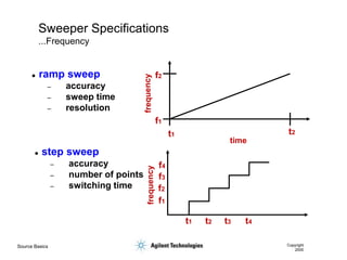
- 21. Source Basics Copyright 2000 Sweeper Specifications ...Frequency ’ü¼ ramp sweep ŌĆō accuracy ŌĆō sweep time ŌĆō resolution ’ü¼ step sweep ŌĆō accuracy ŌĆō number of points ŌĆō switching time time f2 t2 t1 f1 t4 t3 t1 t2 f4 f3 f1 f2
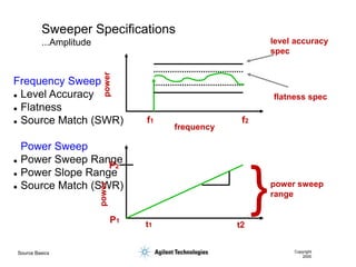
- 22. Source Basics Copyright 2000 Sweeper Specifications ...Amplitude Frequency Sweep ’ü¼ Level Accuracy ’ü¼ Flatness ’ü¼ Source Match (SWR) Power Sweep ’ü¼ Power Sweep Range ’ü¼ Power Slope Range ’ü¼ Source Match (SWR) flatness spec level accuracy spec f1 f2 frequency power power } P2 P1 power sweep range t1 t2
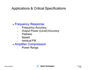
- 23. Source Basics Copyright 2000 Applications & Critical Specifications ’ü¼ Frequency Response ŌĆō Frequency Accuracy ŌĆō Output Power (Level) Accuracy ŌĆō Flatness ŌĆō Speed ŌĆō residual FM ’ü¼ Amplifier Compression ŌĆō Power Range
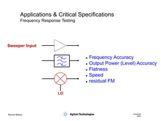
- 24. Source Basics Copyright 2000 Applications & Critical Specifications Frequency Response Testing LO Sweeper Input ’ü¼ Frequency Accuracy ’ü¼ Output Power (Level) Accuracy ’ü¼ Flatness ’ü¼ Speed ’ü¼ residual FM
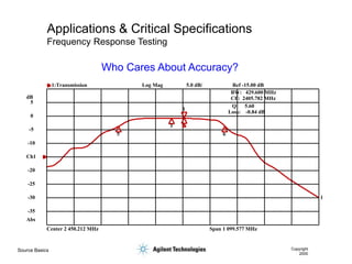
- 25. Source Basics Copyright 2000 Applications & Critical Specifications Frequency Response Testing Center 2 450.212 MHz Span 1 099.577 MHz 1 1 3 5 6 BW: 429.600 MHz CF: 2405.782 MHz Q: 5.60 Loss: -0.84 dB 1:Transmission Log Mag 5.0 dB/ Ref -15.00 dB -35 -30 -25 -20 -10 -5 0 5 Abs dB Ch1 Who Cares About Accuracy?
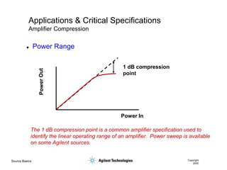
- 26. Source Basics Copyright 2000 Applications & Critical Specifications Amplifier Compression Power In 1 dB compression point The 1 dB compression point is a common amplifier specification used to identify the linear operating range of an amplifier. Power sweep is available on some Agilent sources. ’ü¼ Power Range
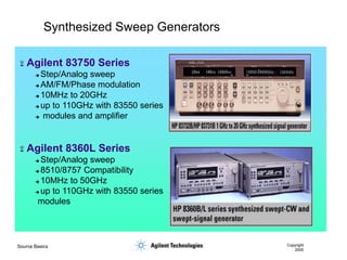
- 27. Source Basics Copyright 2000 Synthesized Sweep Generators ’ĆČ Agilent 83750 Series ’ā© Step/Analog sweep ’ā© AM/FM/Phase modulation ’ā© 10MHz to 20GHz ’ā© up to 110GHz with 83550 series ’ā© modules and amplifier ’ĆČ Agilent 8360L Series ’ā© Step/Analog sweep ’ā© 8510/8757 Compatibility ’ā© 10MHz to 50GHz ’ā© up to 110GHz with 83550 series modules
- 28. Source Basics Copyright 2000 Agenda ’ü¼ Types of sources ’ü¼ CW ’ü¼ Swept ’ü¼ Signal Generator ’ü¼ Block Diagrams ’ü¼ Applications ’ü¼ Specifications
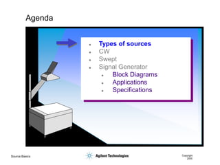
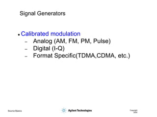
- 29. Source Basics Copyright 2000 Signal Generators ’ü¼ Calibrated modulation ŌĆō Analog (AM, FM, PM, Pulse) ŌĆō Digital (I-Q) ŌĆō Format Specific(TDMA,CDMA, etc.)
- 30. Source Basics Copyright 2000 Modulation ...Where the information resides AM, Pulse FM PM q V= A(t) sin[ (t)] p V= A(t) sin[2 f(t) + (t)] f
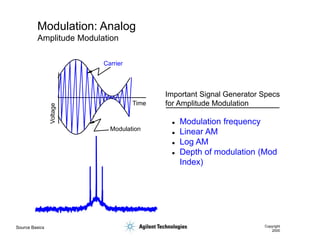
- 31. Source Basics Copyright 2000 Modulation: Analog Amplitude Modulation Important Signal Generator Specs for Amplitude Modulation Voltage Time Carrier Modulation ’ü¼ Modulation frequency ’ü¼ Linear AM ’ü¼ Log AM ’ü¼ Depth of modulation (Mod Index)
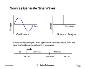
- 32. Source Basics Copyright 2000 Modulation: Analog Frequency Modulation Voltage Time Important Signal Generator Specs for Frequency Modulation V= A sin[2 f t + m(t)] p c b F /F dev mod b = D ’ü¼ Frequency Deviation ’ü¼ Modulation Frequency ’ü¼ dcFM ’ü¼ Accuracy ’ü¼ Resolution
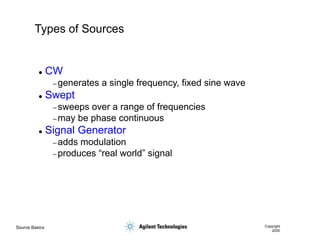
- 33. Source Basics Copyright 2000 Modulation: Analog Phase Modulation b = Df peak V= A sin[2 p f t + m(t)] Important Signal Generator Specs for Phase Modulation ’ü¼ Phase deviation ’ü¼ Rates ’ü¼ Accuracy ’ü¼ Resolution Voltage Time c b
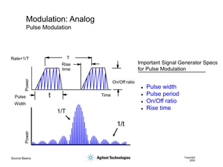
- 34. Source Basics Copyright 2000 Modulation: Analog Pulse Modulation Time Pulse On/Off ratio Rise time Rate=1/T T Width Power t 1/t 1/T Power Important Signal Generator Specs for Pulse Modulation ’ü¼ Pulse width ’ü¼ Pulse period ’ü¼ On/Off ratio ’ü¼ Rise time
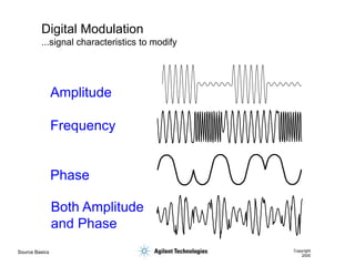
- 35. Source Basics Copyright 2000 Digital Modulation ...signal characteristics to modify Amplitude Frequency Phase Both Amplitude and Phase
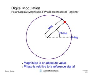
- 36. Source Basics Copyright 2000 Digital Modulation Polar Display: Magnitude & Phase Represented Together ’ü¼ Magnitude is an absolute value ’ü¼ Phase is relative to a reference signal Phase 0 deg
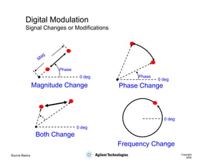
- 37. Source Basics Copyright 2000 Digital Modulation Signal Changes or Modifications Phase 0 deg Magnitude Change Phase 0 deg Phase Change Frequency Change Both Change 0 deg 0 deg
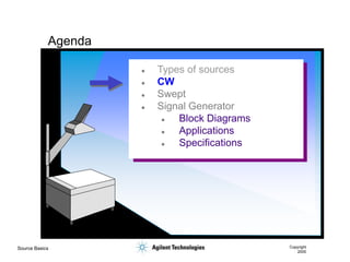
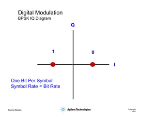
- 38. Source Basics Copyright 2000 Digital Modulation ...Binary Phase Shift Keying (BPSK) f V= A sin[2 ft + (t)] (t) = f1 f2 p f
- 39. Source Basics Copyright 2000 Digital Modulation BPSK IQ Diagram I Q 0 1 One Bit Per Symbol Symbol Rate = Bit Rate
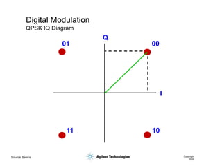
- 40. Source Basics Copyright 2000 Digital Modulation ...Quadrature Phase Shift Keying (QPSK) V= A sin[2 ft + (t)] f(t) = f1 = 3 /4 p f2 = /4 p f3 = - /4 p f4 = - 3 /4 p p f
- 41. Source Basics Copyright 2000 Digital Modulation QPSK IQ Diagram I Q 00 01 10 11
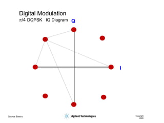
- 42. Source Basics Copyright 2000 Digital Modulation p/4 DQPSK IQ Diagram I Q
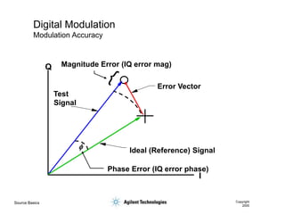
- 43. Source Basics Copyright 2000 Digital Modulation Modulation Accuracy I Q Magnitude Error (IQ error mag) Error Vector Ideal (Reference) Signal Phase Error (IQ error phase) Test Signal f
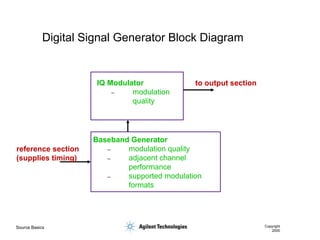
- 44. Source Basics Copyright 2000 Digital Signal Generator Block Diagram IQ Modulator ŌĆō modulation quality Baseband Generator ŌĆō modulation quality ŌĆō adjacent channel performance ŌĆō supported modulation formats reference section (supplies timing) to output section
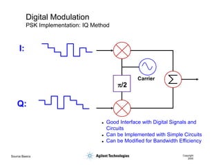
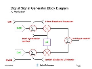
- 45. Source Basics Copyright 2000 Digital Modulation PSK Implementation: IQ Method p/2 Carrier ’ü¼ Good Interface with Digital Signals and Circuits ’ü¼ Can be Implemented with Simple Circuits ’ü¼ Can be Modified for Bandwidth Efficiency I: Q:
- 46. Source Basics Copyright 2000 Digital Signal Generator Block Diagram IQ Modulator p/2 DAC DAC Ext I Ext Q from synthesizer section to output section Q from Baseband Generator I from Baseband Generator
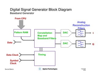
- 47. Source Basics Copyright 2000 Digital Signal Generator Block Diagram Baseband Generator DAC DAC Pattern RAM Constellation Map and Baseband Filters Timing Data Data Clock Symbol Clock From CPU I Q Analog Reconstruction Filters
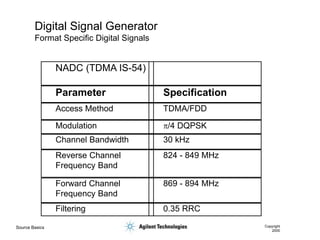
- 48. Source Basics Copyright 2000 Digital Signal Generator Format Specific Digital Signals NADC (TDMA IS-54) Parameter Specification Access Method TDMA/FDD Modulation p/4 DQPSK Channel Bandwidth 30 kHz Reverse Channel Frequency Band 824 - 849 MHz Forward Channel Frequency Band 869 - 894 MHz Filtering 0.35 RRC
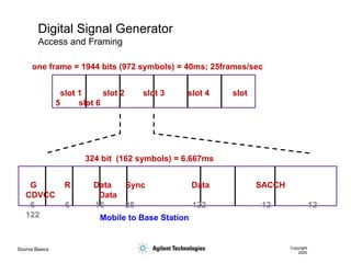
- 49. Source Basics Copyright 2000 Digital Signal Generator Access and Framing one frame = 1944 bits (972 symbols) = 40ms; 25frames/sec slot 1 slot 2 slot 3 slot 4 slot 5 slot 6 324 bit (162 symbols) = 6.667ms G R Data Sync Data SACCH CDVCC Data 6 6 16 28 122 12 12 122 Mobile to Base Station
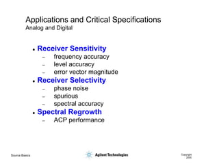
- 50. Source Basics Copyright 2000 Applications and Critical Specifications Analog and Digital ’ü¼ Receiver Sensitivity ŌĆō frequency accuracy ŌĆō level accuracy ŌĆō error vector magnitude ’ü¼ Receiver Selectivity ŌĆō phase noise ŌĆō spurious ŌĆō spectral accuracy ’ü¼ Spectral Regrowth ŌĆō ACP performance
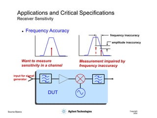
- 51. Source Basics Copyright 2000 Applications and Critical Specifications Receiver Sensitivity Want to measure sensitivity in a channel Measurement impaired by frequency inaccuracy frequency inaccuracy amplitude inaccuracy input for signal generator DUT ’ü¼ Frequency Accuracy
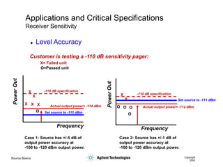
- 52. Source Basics Copyright 2000 Applications and Critical Specifications Receiver Sensitivity Customer is testing a -110 dB sensitivity pager: -110 dB specification Case 1: Source has +/-5 dB of output power accuracy at -100 to -120 dBm output power. Set source to -115 dBm Actual output power= -114 dBm X X X X X O Case 2: Source has +/-1 dB of output power accuracy at -100 to -120 dBm output power. -110 dB specification Set source to -111 dBm Actual output power= -112 dBm X X O O O O X= Failed unit O=Passed unit Frequency Frequency ’ü¼ Level Accuracy
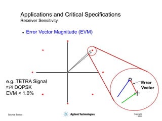
- 53. Source Basics Copyright 2000 Applications and Critical Specifications Receiver Sensitivity ’ü¼ Error Vector Magnitude (EVM) Error Vector p e.g. TETRA Signal /4 DQPSK EVM < 1.0%
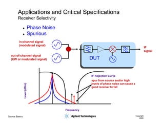
- 54. Source Basics Copyright 2000 Applications and Critical Specifications Receiver Selectivity IF Rejection Curve Frequency Level (dBm) spur from source and/or high levels of phase noise can cause a good receiver to fail IF signal in-channel signal (modulated signal) out-of-channel signal (CW or modulated signal) DUT ’ü¼ Phase Noise ’ü¼ Spurious
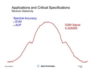
- 55. Source Basics Copyright 2000 Applications and Critical Specifications Receiver Selectivity GSM Signal 0.3GMSK Spectral Accuracy: ’ü¼ EVM ’ü¼ ACP
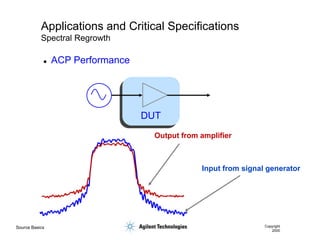
- 56. Source Basics Copyright 2000 Applications and Critical Specifications Spectral Regrowth Input from signal generator Output from amplifier DUT ’ü¼ ACP Performance
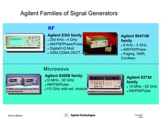
- 57. Source Basics Copyright 2000 Agilent Families of Signal Generators RF Microwave Agilent 8647/48 family ’ü¼ 9 KHz - 4 GHz ’ü¼ AM/FM/Phase ’ü¼ Paging, SMR, Cordless Agilent ESG family ’ü¼ 250 KHz - 4 GHz ’ü¼ AM/FM/Phase/Pulse ’ü¼ Digital/I-Q Mod ’ü¼ GSM,CDMA,DECT... Agilent 8360B family ’ü¼10 MHz - 50 GHz ’ü¼ AM/FM/Pulse ’ü¼110 GHz with ext. module Agilent 83730 family ’ü¼ 10 MHz - 20 GHz ’ü¼ AM/FM/Pulse
- 58. Source Basics Copyright 2000 ’ü¼ Types of sources ’ü¼ CW ’ü¼ Swept ’ü¼ Signal Generator ’ü¼ Block Diagrams ’ü¼ Applications ’ü¼ Specifications Agenda