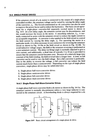
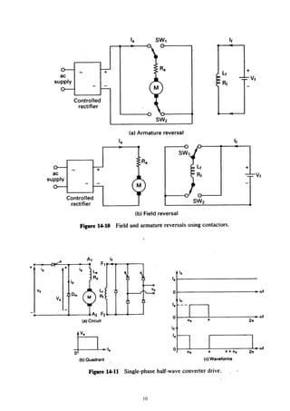
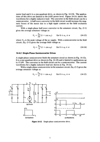
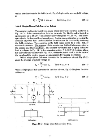
2. dc drive
Download as doc, pdf0 likes286 views
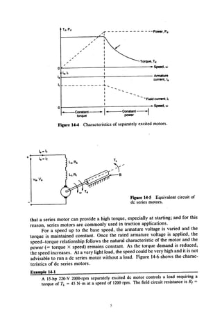
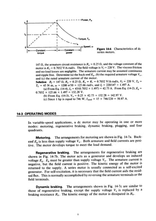
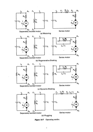
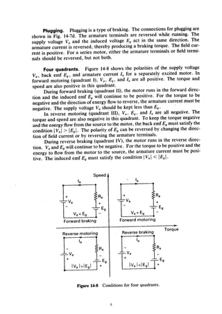
Electrical Drive lecture 3b notes for HD in Electrical Engineering
1 of 32
Download to read offline
Ad
Recommended
Estudos b├Łblicos como ler e compreender a b├Łblia
Estudos b├Łblicos como ler e compreender a b├ŁbliaRegis A. Feitosa
╠²
S├®rie de estudos b├Łblicos da igreja adventistas.Estudos b├Łblicos a verdadeira igreja
Estudos b├Łblicos a verdadeira igrejaRegis A. Feitosa
╠²
S├®rie de estudos b├Łblicos da igreja adventistasEstudos b├Łblicos a segunda vinda de cristo
Estudos b├Łblicos a segunda vinda de cristoRegis A. Feitosa
╠²
S├®rie de estudos b├Łblicos da igreja adventistasVerdades B├Łblicas - Padr├Ąes Crist├Żos
Verdades B├Łblicas - Padr├Ąes Crist├ŻosConectadoscomjesusiasd
╠²
Verdades B├Łblicas - Padr├Ąes Crist├ŻosPortf├│lio "i am fashion" ss 2015 16
Portf├│lio "i am fashion" ss 2015 16Eun Mi Kim
╠²
Apresenta├¦├Żo dos design "I AM FASHION (I.A.F)" do SS 2015-16Verdades B├Łblicas - O Dom de Profecia
Verdades B├Łblicas - O Dom de ProfeciaConectadoscomjesusiasd
╠²
Verdades B├Łblicas - O Dom de Profecia1. revision on 3 phase conventional inverter
1. revision on 3 phase conventional inverterbenson215
╠²
This document discusses revisions made to a 3-phase conventional inverter. The inverter is used to convert DC power from sources like solar panels into 3-phase AC power that can be fed into the electric grid or used by electric motors. Some changes were made to the control system and components to improve the inverter's performance and efficiency.2. ac drive (common inverter drive)
2. ac drive (common inverter drive)benson215
╠²
Electrical Drive lecture 4b notes for HD in Electrical Engineering2. motor drive dynamic
2. motor drive dynamicbenson215
╠²
This document discusses dimensioning a drive system, including:
1. The general steps of dimensioning including selecting the motor and frequency converter.
2. Common load types like constant torque, quadratic torque, and constant power loads.
3. How a motor's thermal loadability decreases at lower speeds for self-ventilated motors, but separate cooling allows overloading at low speeds.5. two phase servo motor
5. two phase servo motorbenson215
╠²
A 2-phase servo motor is described with 17 numbered points providing details about its construction and operation. Key details include that it uses 2 energized coils to rotate the motor shaft in either direction and has a feedback potentiometer to sense shaft position and complete a control loop.3. relutance and hysteresis motor
3. relutance and hysteresis motorbenson215
╠²
Electrical Drive lecture 1c notes for HD in Electrical Engineering2. brushless dc motors
2. brushless dc motorsbenson215
╠²
This document provides an overview of brushless DC motors. It discusses their structure, drive circuits, equivalent circuit model, and performance characteristics. Brushless DC motors have a rotor with permanent magnets and stator windings similar to AC motors. They use electronic commutation instead of brushes and commutators, making them maintenance-free. The document covers various drive circuit topologies including unipolar and bipolar drives. It also presents the dynamic and steady-state equivalent circuits and performance equations of brushless DC motors.4. linear motor basics
4. linear motor basicsbenson215
╠²
1. A linear induction motor is essentially a rotating squirrel cage induction motor that has been opened out flat, producing linear force instead of rotary torque.
2. Linear motors have advantages like no moving parts, silent operation, and ease of control and installation. Applications include sliding doors, conveyors, and vehicle propulsion.
3. Linear motors require an AC power supply and speed can be controlled through phase control or feedback systems. Different linear motor designs exist including ironcore, aircore, and slotless types.Eee3420 lecture06 rev2011
Eee3420 lecture06 rev2011benson215
╠²
This document provides an overview of sequential function charts (SFC) for process control design. It defines SFCs as a graphical programming language used to describe control sequences. The key components of SFCs are defined as steps, transitions, and actions. Various SFC structures are presented, including simple sequences, parallel sequences, and branching sequences. Implementation of SFCs using ladder logic and sequence bits is also described. An example of using SFCs to control a three-floor lift is presented to illustrate how SFCs can be applied to model sequential process control applications.1. servo basic
1. servo basicbenson215
╠²
This document provides an introduction to servo systems, including:
1. It defines a servo system as one that controls mechanical devices in compliance with varying position or speed target values from a command.
2. It describes three major types of control systems - open loop, semi-closed loop, and full-closed loop - and compares their features such as precision, ability to handle load fluctuations, and complexity.
3. It outlines the typical components of a servo system, including the servo motor, detector, driver, and position controller, and describes how they work together to provide position and speed feedback control of the motor.Eee3420 lecture07 rev2011
Eee3420 lecture07 rev2011benson215
╠²
This document provides an overview of communication protocols and PLC communication techniques. It begins with learning objectives to understand communication protocols and PLC communication. It then introduces industrial networks and how multiple control systems like PLCs, robots, and computers must communicate to work together. It discusses various communication methods including serial, parallel, transmission rates and distances. It also covers topics like industrial network characteristics, hierarchy, response times, bandwidth, efficiency, access methods, topologies, number of devices, capabilities, message lengths, vendor support, OSI models, traditional industrial networks like DeviceNet and Profibus, and serial communication standards like RS-232.1. revision on 3 phase controlled rectifier
1. revision on 3 phase controlled rectifierbenson215
╠²
This document discusses a 3-phase controlled rectifier circuit that uses thyristors to control the rectification of a 3-phase AC input. The circuit allows controlling the DC output voltage by adjusting the firing angle of the thyristors. When the thyristors are fired earlier in their half-cycles, more voltage will be rectified and added to the DC output.Eee3420 lecture08 rev2011
Eee3420 lecture08 rev2011benson215
╠²
This document provides an overview of sensors, actuators, and programmable logic controller (PLC) applications in industrial control. It discusses various types of common sensors such as inductive proximity, capacitive, optical, and mechanical contact sensors. It also describes actuator types including solenoids, valves, cylinders, and motors. Finally, it provides examples of how PLCs can be used with these sensors and actuators for industrial automation and control applications.Eee3420 lecture05 rev2011
Eee3420 lecture05 rev2011benson215
╠²
This document discusses designing control processes using flowchart techniques. It begins by defining the basic components of a flowchart like blocks, arrows, and decision points. It then provides examples of implementing simple sequential processes as flowcharts, including a water tank filling process. The document explains two methods for representing flowcharts in ladder logic programs using block logic or sequence bits. Finally, it presents a example of using flowcharts and high-level instructions to control the movement of a cart system.Eee3420 lecture03 rev2011
Eee3420 lecture03 rev2011benson215
╠²
This document provides an overview of programmable logic controller (PLC) programming. It discusses the IEC 61131 standards for PLC programming languages including ladder logic, sequential function charts, function block diagrams, structured text, and instruction list. It also provides examples of programming basics like logic gates, latches, timers, and shift registers in ladder logic for different PLC brands like Allen-Bradley, Mitsubishi, and Omron.Eee3420 lecture04 rev2011
Eee3420 lecture04 rev2011benson215
╠²
This document provides an overview of an advanced PLC programming lecture for a course on industrial control. It discusses the structure and programming of Mitsubishi FX series PLCs, including details on hardware components like inputs, outputs, auxiliary relays and data registers. It also covers advanced programming techniques like special instructions, representation of operands, and data formats including bit devices, word devices, signed binary, hexadecimal, BCD, scientific notation and floating point values.More Related Content
What's hot (7)
Verdades B├Łblicas - Padr├Ąes Crist├Żos
Verdades B├Łblicas - Padr├Ąes Crist├ŻosConectadoscomjesusiasd
╠²
Verdades B├Łblicas - Padr├Ąes Crist├ŻosPortf├│lio "i am fashion" ss 2015 16
Portf├│lio "i am fashion" ss 2015 16Eun Mi Kim
╠²
Apresenta├¦├Żo dos design "I AM FASHION (I.A.F)" do SS 2015-16Verdades B├Łblicas - O Dom de Profecia
Verdades B├Łblicas - O Dom de ProfeciaConectadoscomjesusiasd
╠²
Verdades B├Łblicas - O Dom de ProfeciaViewers also liked (17)
1. revision on 3 phase conventional inverter
1. revision on 3 phase conventional inverterbenson215
╠²
This document discusses revisions made to a 3-phase conventional inverter. The inverter is used to convert DC power from sources like solar panels into 3-phase AC power that can be fed into the electric grid or used by electric motors. Some changes were made to the control system and components to improve the inverter's performance and efficiency.2. ac drive (common inverter drive)
2. ac drive (common inverter drive)benson215
╠²
Electrical Drive lecture 4b notes for HD in Electrical Engineering2. motor drive dynamic
2. motor drive dynamicbenson215
╠²
This document discusses dimensioning a drive system, including:
1. The general steps of dimensioning including selecting the motor and frequency converter.
2. Common load types like constant torque, quadratic torque, and constant power loads.
3. How a motor's thermal loadability decreases at lower speeds for self-ventilated motors, but separate cooling allows overloading at low speeds.5. two phase servo motor
5. two phase servo motorbenson215
╠²
A 2-phase servo motor is described with 17 numbered points providing details about its construction and operation. Key details include that it uses 2 energized coils to rotate the motor shaft in either direction and has a feedback potentiometer to sense shaft position and complete a control loop.3. relutance and hysteresis motor
3. relutance and hysteresis motorbenson215
╠²
Electrical Drive lecture 1c notes for HD in Electrical Engineering2. brushless dc motors
2. brushless dc motorsbenson215
╠²
This document provides an overview of brushless DC motors. It discusses their structure, drive circuits, equivalent circuit model, and performance characteristics. Brushless DC motors have a rotor with permanent magnets and stator windings similar to AC motors. They use electronic commutation instead of brushes and commutators, making them maintenance-free. The document covers various drive circuit topologies including unipolar and bipolar drives. It also presents the dynamic and steady-state equivalent circuits and performance equations of brushless DC motors.4. linear motor basics
4. linear motor basicsbenson215
╠²
1. A linear induction motor is essentially a rotating squirrel cage induction motor that has been opened out flat, producing linear force instead of rotary torque.
2. Linear motors have advantages like no moving parts, silent operation, and ease of control and installation. Applications include sliding doors, conveyors, and vehicle propulsion.
3. Linear motors require an AC power supply and speed can be controlled through phase control or feedback systems. Different linear motor designs exist including ironcore, aircore, and slotless types.Eee3420 lecture06 rev2011
Eee3420 lecture06 rev2011benson215
╠²
This document provides an overview of sequential function charts (SFC) for process control design. It defines SFCs as a graphical programming language used to describe control sequences. The key components of SFCs are defined as steps, transitions, and actions. Various SFC structures are presented, including simple sequences, parallel sequences, and branching sequences. Implementation of SFCs using ladder logic and sequence bits is also described. An example of using SFCs to control a three-floor lift is presented to illustrate how SFCs can be applied to model sequential process control applications.1. servo basic
1. servo basicbenson215
╠²
This document provides an introduction to servo systems, including:
1. It defines a servo system as one that controls mechanical devices in compliance with varying position or speed target values from a command.
2. It describes three major types of control systems - open loop, semi-closed loop, and full-closed loop - and compares their features such as precision, ability to handle load fluctuations, and complexity.
3. It outlines the typical components of a servo system, including the servo motor, detector, driver, and position controller, and describes how they work together to provide position and speed feedback control of the motor.Eee3420 lecture07 rev2011
Eee3420 lecture07 rev2011benson215
╠²
This document provides an overview of communication protocols and PLC communication techniques. It begins with learning objectives to understand communication protocols and PLC communication. It then introduces industrial networks and how multiple control systems like PLCs, robots, and computers must communicate to work together. It discusses various communication methods including serial, parallel, transmission rates and distances. It also covers topics like industrial network characteristics, hierarchy, response times, bandwidth, efficiency, access methods, topologies, number of devices, capabilities, message lengths, vendor support, OSI models, traditional industrial networks like DeviceNet and Profibus, and serial communication standards like RS-232.1. revision on 3 phase controlled rectifier
1. revision on 3 phase controlled rectifierbenson215
╠²
This document discusses a 3-phase controlled rectifier circuit that uses thyristors to control the rectification of a 3-phase AC input. The circuit allows controlling the DC output voltage by adjusting the firing angle of the thyristors. When the thyristors are fired earlier in their half-cycles, more voltage will be rectified and added to the DC output.Eee3420 lecture08 rev2011
Eee3420 lecture08 rev2011benson215
╠²
This document provides an overview of sensors, actuators, and programmable logic controller (PLC) applications in industrial control. It discusses various types of common sensors such as inductive proximity, capacitive, optical, and mechanical contact sensors. It also describes actuator types including solenoids, valves, cylinders, and motors. Finally, it provides examples of how PLCs can be used with these sensors and actuators for industrial automation and control applications.Eee3420 lecture05 rev2011
Eee3420 lecture05 rev2011benson215
╠²
This document discusses designing control processes using flowchart techniques. It begins by defining the basic components of a flowchart like blocks, arrows, and decision points. It then provides examples of implementing simple sequential processes as flowcharts, including a water tank filling process. The document explains two methods for representing flowcharts in ladder logic programs using block logic or sequence bits. Finally, it presents a example of using flowcharts and high-level instructions to control the movement of a cart system.Eee3420 lecture03 rev2011
Eee3420 lecture03 rev2011benson215
╠²
This document provides an overview of programmable logic controller (PLC) programming. It discusses the IEC 61131 standards for PLC programming languages including ladder logic, sequential function charts, function block diagrams, structured text, and instruction list. It also provides examples of programming basics like logic gates, latches, timers, and shift registers in ladder logic for different PLC brands like Allen-Bradley, Mitsubishi, and Omron.Eee3420 lecture04 rev2011
Eee3420 lecture04 rev2011benson215
╠²
This document provides an overview of an advanced PLC programming lecture for a course on industrial control. It discusses the structure and programming of Mitsubishi FX series PLCs, including details on hardware components like inputs, outputs, auxiliary relays and data registers. It also covers advanced programming techniques like special instructions, representation of operands, and data formats including bit devices, word devices, signed binary, hexadecimal, BCD, scientific notation and floating point values.Eee3420 lecture02 rev2011
Eee3420 lecture02 rev2011benson215
╠²
This document provides an overview of programmable logic controllers (PLCs) and their hardware components. It discusses the basic components of a PLC including the power supply, central processing unit, input/output terminals, and indicator lights. It also describes common input and output devices used with PLCs such as sensors, actuators, and relays. The document discusses how inputs are connected to a PLC and converted to a format readable by its logic. It also describes how PLCs convert internal logic levels to external voltage levels on the outputs. Finally, it summarizes key aspects of PLC hardware and wiring.3. ac drive (misc.)
3. ac drive (misc.)benson215
╠²
(1) The document discusses AC drive systems including AC voltage controllers, cycloconverters, and PWM control.
(2) AC voltage controllers are used to control the speed of AC induction motors by varying the firing angle. Cycloconverters can generate variable frequency output from a fixed frequency input using a dual converter configuration.
(3) PWM control improves performance over simple voltage control by reducing harmonic content in the output waveform. Advanced PWM techniques like sinusoidal, trapezoidal, and stepped modulation further optimize the output waveform.Ad
More from benson215 (13)
Chapter 5 - DC-AC Conversion.pdf
Chapter 5 - DC-AC Conversion.pdfbenson215
╠²
This document discusses DC to AC conversion using inverters. It describes various inverter topologies including single phase half bridge and full bridge inverters as well as three phase full bridge inverters. It discusses modulation techniques such as sinusoidal pulse width modulation to generate sinusoidal AC outputs. Examples of applications like motor drives and solar power generation are provided.Chapter 0 - Introduction.pdf
Chapter 0 - Introduction.pdfbenson215
╠²
This document introduces an advanced power electronics course. It discusses the lecturer's background and qualifications. It outlines some ground rules for students, including submitting assignments on time, maintaining academic integrity, and being respectful. It then provides a general overview of the course, defining power electronics and discussing some key applications like power supplies, inverters, and motor drives. It also introduces some important power electronic components like capacitors, inductors, diodes, and active switching devices.Chapter 1 - PWM DC-DC Converter.pdf
Chapter 1 - PWM DC-DC Converter.pdfbenson215
╠²
This document provides an overview of pulse-width modulated (PWM) DC/DC converters. It discusses typical applications, topologies including non-isolated converters like buck, boost and buck-boost converters. The principles of DC/DC converters like conversion ratio and voltage/current waveforms are introduced. Modes of operation for buck converters in continuous and discontinuous mode are examined. Component ratings for voltage and current are also covered.Chapter 2 - Isolated DC-DC Converter.pdf
Chapter 2 - Isolated DC-DC Converter.pdfbenson215
╠²
This document summarizes different types of isolated DC/DC converters. It discusses flyback converters, which are derived from buck-boost converters by adding a coupled inductor. Flyback converters can operate in continuous or discontinuous mode. Phase-shift full-bridge converters are suitable for high power applications. They consist of a full-bridge inverter and rectifier, with legs switched alternately at different phases to regulate output voltage. The document also reviews transformer fundamentals and voltage conversion ratios for different isolated converter types.Chapter 3 - Resonant-mode DC-DC Converter.pdf
Chapter 3 - Resonant-mode DC-DC Converter.pdfbenson215
╠²
This chapter discusses resonant DC/DC converters. Hard-switching converters experience high switching losses which reduce efficiency. Resonant converters reduce switching losses by forcing zero-current or zero-voltage switching through resonant circuits. This is accomplished by adding inductors and capacitors to shape current and voltage waveforms. While more efficient, resonant converters have more complex circuitry than hard-switching converters.Chapter 6 - Modelling and Control of Converters.pdf
Chapter 6 - Modelling and Control of Converters.pdfbenson215
╠²
This document discusses modeling and control of power converters. It begins by explaining that converters are typically controlled with closed-loop control to maintain regulated output levels despite variations, rather than open-loop control. It then covers obtaining small-signal dynamic models of converters using state-space averaging techniques to design closed-loop controllers. As an example, it derives the small-signal model of a buck converter in continuous mode through state-space equations, averaging, linearization, and Laplace transformation to obtain a transfer function. The document provides procedures for modeling other converters and analyzing converter characteristics from the frequency-domain models.Chapter 4 - AC-DC Conversion.pdf
Chapter 4 - AC-DC Conversion.pdfbenson215
╠²
This document summarizes Chapter 4 of a textbook on AC/DC and DC/AC conversion. It discusses uncontrollable and controllable AC-DC converters, including rectifiers, power factor, and harmonics. It then covers full-wave and controlled rectifiers, thyristor triggering, and integrated power modules. The document also discusses power factor correction, harmonic distortion, and total harmonic distortion. Finally, it summarizes various power quality issues faced by utilities.Chapter 7 - EMI.pdf
Chapter 7 - EMI.pdfbenson215
╠²
This document discusses electromagnetic interference (EMI) in power electronics. It defines EMI and describes how it is generated internally in power electronic circuits and transmitted through electrical conduction, electromagnetic induction, and radiation. The document outlines international standards for EMI, sources of EMI, and methods for suppressing EMI, including EMI filters, active harmonic compensation, and proper design of circuit components.Eee3420 lecture01 rev2011
Eee3420 lecture01 rev2011benson215
╠²
This document provides an overview of control systems and various control strategies. It discusses open-loop and closed-loop control systems, transfer functions, PID control, stability criteria, and analysis methods like using transfer functions and Routh tables. The key topics covered include proportional, integral and derivative control actions, tuning PID controllers, modeling systems using Laplace transforms, and factors that determine the stability of first-order and higher-order systems. Real-world examples on thermal control systems are provided to illustrate different control techniques.Eee3420 lecture08 rev2011
Eee3420 lecture08 rev2011benson215
╠²
This document discusses sensors, actuators, and applications of programmable logic controllers (PLCs) in industrial control. It describes various types of sensors such as inductive, capacitive, optical, and ultrasonic sensors and how they are used to detect physical phenomena. It also discusses different methods of connecting sensors to PLCs including sinking/sourcing, switches, and transistor-transistor logic. Common uses of actuators controlled by PLCs are also covered. The overall purpose is to explain how sensors and actuators are used in industrial automation applications controlled by PLCs.Eee3420 lecture07 rev2011
Eee3420 lecture07 rev2011benson215
╠²
This document discusses communication protocols and techniques for programmable logic controllers (PLCs). It covers topics like industrial network characteristics, hierarchy of industrial networks, response time and variance, bandwidth, efficiency, access methods, topology, distance limitations, number of devices, device capabilities, and length of messages. The goal is for students to understand how different control systems like PLCs communicate with each other in complex industrial processes.Eee3420 lecture06 rev2011
Eee3420 lecture06 rev2011benson215
╠²
This document discusses sequential function charts (SFC), which are a graphical programming language used to design process control systems. SFC uses symbols like steps, transitions, and actions to describe the sequence and logic of a control program. It introduces the basic components of SFC like steps, transitions, actions, and qualifiers. It also explains the basic structures that can be represented with SFC, including simple sequences, alternative parallel sequences, and simultaneous parallel sequences. Finally, it provides examples of implementing simple sequences, alternative sequences, and simultaneous sequences using ladder logic.Eee3420 lecture05 rev2011
Eee3420 lecture05 rev2011benson215
╠²
This document discusses flowchart-based process control design using programmable logic controllers (PLCs). It covers creating flowcharts to represent sequential processes, and implementing those flowcharts in PLC programs using block logic or sequence bits. High-level flowchart representations of processes can be realized using high-level instructions from PLCs like the Mitsubishi FX. An example cart control system flowchart is implemented using MOV, CMP and other FX instructions to move the cart between positions based on limit switch and call button inputs.Ad